How to Replace the Directional Pad on New Nintendo 3DS XL
Duration: 45 minutes
Steps: 18 Steps
Is your Nintendo 3DS XL 2015’s directional pad on the fritz? No worries! This handy guide will show you how to get it working like a champ again.
Step 1

Power down your device before we jump in. Trust me, you don’t want to meet Mr. Electrical Shock or damage your gadget.
– Flip your 3DS over like it’s taking a little nap. Go ahead and gently take out the game card, headphones, charging cable, stylus, or anything else that’s hanging out with your device. Time to give it some space!
Step 2

The screws are secured with captive washers, so just give them a gentle twist and leave them in place. No need to take them all the way out!
– Grab your trusty JIS #0 screwdriver and loosen those two black screws on the back. You’ve got this!
Step 3

– After you’ve given those screws a little twist to loosen them up, go ahead and gently pry open the back cover. You’re doing great!
Step 4

– Alright, the battery’s chilling on the left side of your 3DS. To evict it, spot that tiny gap up top and gently coax it out with a non-metal pointy thing. Easy peasy!
Step 5

– Grab your trusty JIS #00 screwdriver and let’s get to work! Carefully unscrew the six 6mm screws that are hanging out around the edges of the secondary cover. You’ve got this!
Step 6


– Grab those tweezers and gently pop out the rubber bumpers chilling at the top of your 3DS. Underneath, you’ll uncover two sneaky 6mm screws waiting to be tackled! Use your trusty JIS #000 screwdriver to unscrew them and keep the vibe going.
Tools Used

Step 7

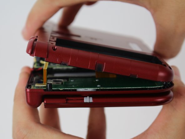

Hold on a sec! Don’t take the cover off just yet, or you might risk hurting that fragile ribbon cable still attached to the motherboard.
– It’s time to get this repair party started! To separate the cover, gently pry it up and away from the hinges – don’t forget to clear that headphone port – then swing it towards the hinges to reveal the circuit boards inside.
Step 8

– Grab some trusty tweezers and gently lift up the two little plugs holding the L/R/ZL/ZR button ribbons onto the motherboard. Once those are free, you can completely remove the back cover and set it aside. Nice work!
Tools Used
Step 9

Alright, heads up! The cable loops over itself to slide into the ZIF connector from the left, while the locking flap opens up from the right. It’s a classic mix-up to tug on the side where the cable sits—that’s a surefire way to snap the connector, so handle it with care!
For an easier time, try unscrewing and popping off the Circle Pad first before tackling that cable disconnection. When it’s time to put the Circle Pad back on, reconnect that cable first and then gently set the unit back in place. You’ve got this!
– Grab your trusty tweezers and gently lift that small, hinged locking flap to free the ZIF connector that’s holding the Circle Pad ribbon hostage.
– Now, smoothly slide that ribbon out of the ZIF connector like a pro!
Tools Used
Step 10

– Grab your trusty JIS #000 screwdriver and unscrew the two 8 mm bolts holding the circle pad in place. You’ve got this!
Step 11

– Time to get started! Gently pry the circle pad casing upward – it might take a bit of effort, but don’t worry, it shouldn’t require superhuman strength. Take your time, and it’ll come off in no time.
Step 12

Careful there, friend! Tug gently and avoid yanking that red cable—unless you’re looking for a shocking surprise!
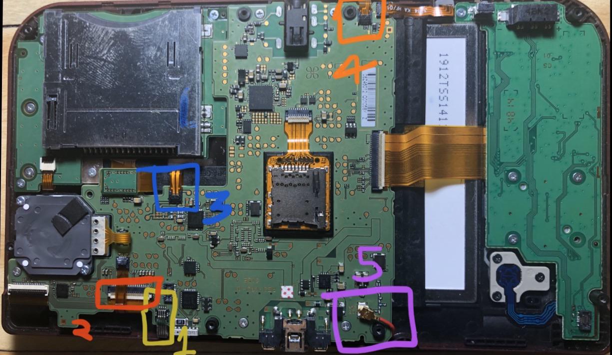
– Alright, champ! Spot that gold terminal plug with the bright red cable chilling at the top left of the motherboard. Now, with those nimble fingers of yours, gently lift that plug straight up and away. You got this!
– Snag your trusty tweezers and let’s disconnect that lone ribbon connector. Easy peasy!
Tools Used
Step 13


These ZIF connectors are like friendly little gremlins—they hold everything in place just by being snug, no locks required! But be careful, lifting their flaps can lead to a bad day, so keep it gentle!
This connector was previously thought to be one of the no-lock crew, but surprise! Most systems actually have a lock. Trying to wiggle this cable out without unlocking it first? That’s a surefire way to mess up the cable and say hello to a new Touch Screen digitizer. The good news? The LCD has other ZIF connectors that are still in the game, so no need to stress about that!
If it turns out your connector is one of the chill ones without a lock, don’t yank that flap! It should pop up like an easy-going buddy; if it’s playing hard to get, it’s probably just holding onto the cable with its friction magic. In that case, give the cable a gentle pull to free it from the connector.
No sweat if the SD card reader is still there, it’s just chilling in the photo but doesn’t need to be removed to get to the motherboard. Keep rockin’!
– Alright, grab those tweezers and carefully wiggle the four highlighted ribbons out of their snug little ZIF connectors along the motherboard’s edges.
– Three of these ribbon connectors have tiny plastic flaps that act like seatbelts for the ribbons. Use your tweezers to gently flip those flaps up before you pull out the ribbons. Safety first, even for cables!
– The last ribbon connector might also have a flap, but it works a bit differently. It’s more like the one used for the Circle Pad. Just give the flap on the side opposite the ribbon cable a gentle lift, and voilà, the ribbon’s free to go.
– When it’s time to put your device back together, don’t forget to flip those ZIF clamps back down to lock everything in place. Smooth sailing!
Tools Used
Step 14

– Grab a JIS #000 screwdriver and carefully remove those six 4mm screws along the edges of the motherboard. You got this!
Step 15


Pay close attention to how the ribbons slide into their connectors, as they have their own special style.
– Gently rotate the motherboard 90 degrees towards the hinges to uncover two additional ZIF connectors hiding on the underside of the motherboard.
– Each connector has a latch that needs to be flipped up. The longer latch on the left is black, while the shorter one on the right is white. Lift those flaps, slide the ribbons out, and say goodbye to the motherboard!
Step 16

– Grab your trusty JIS #000 screwdriver and take out those five 5mm screws from the game card reader panel. You’re doing great!
– Now that the screws are out, it’s time to gently lift out the game card reader. Easy peasy! If you need help, you can always schedule a repair.
Step 17

– Grab your trusty JIS #000 screwdriver and tackle those four 3mm screws holding the square panel in place.
– Once those screws are out of the way, gently lift the panel upwards to free it. You’ve got this!

Success!