How to Replace Thermal Putty and Paste in Xbox Series X
Duration: 45 minutes
Steps: 55 Steps
Get ready to give your Xbox Series X some much-needed TLC! Over time, the thermal paste can dry up, leaving your processor feeling a bit too toasty. While the thermal putty is tougher, it can still lose its charm or get a bit torn during your adventures in disassembly. This guide will walk you through replacing both the thermal paste and putty. Remember, every time you lift that motherboard, it’s time for a thermal paste refresh. And guess what? This guide also helps you out if you’re swapping out the motherboard! If you need help, you can always schedule a repair.
Step 1


Hey there tech wizard! Before we dive in, make sure to fully power down your console and unplug all cables. Let’s keep everything safe and sound!
– Grab your trusty tweezers and carefully peel off the sticker that’s covering up the first screw on the back panel, right near the base.
Tools Used

Step 2


For a smoother removal, give the sticker a bit of heat with a hair dryer or an iOpener. Trust me, it makes the job easier.
Peel the sticker just enough to reveal the hidden screw underneath. No need to yank the whole thing off—keep it simple.
These stickers may be tamper-evident, but don’t sweat it. As long as you’re careful and don’t cause any damage, your warranty is still good. Relax and enjoy the process!
– Time to get started! Use a pair of trusty blunt tweezers to carefully peel back the large sticker on the back panel, and voilà! You’ll reveal the second screw, waiting to be set free.
Tools Used


Step 3

As you dive into this repair, keep tabs on each screw and make sure it finds its way back to its original spot—your console will thank you!
– Let’s get started! Use a T8 Torx driver to remove the two 7.4mm-long screws that hold the back panel in place. Easy peasy!
Step 4


– Slide the flat end of a spudger into the groove between the back panel and the outer shell on the left side of the base.
– Gently pop the back panel loose by prying it up to release those stubborn locking clips.
Tools Used

Step 5


– Start by inserting the flat end of a spudger into the gap between the back panel and the shell, near the right side of the base. This is where the magic begins!
– Gently pry up the back panel to release it from the locking clips. You got this!
Tools Used
Step 6


– Grab the back panel at the spot you just opened up and gently pull it up and away from the shell to release those long edges.
– When you’re putting it all back together, give a little press along the edges of the back panel to snap it back into place.
Step 7


Slide the back panel snugly into the groove at the top of the shell—it fits like a glove!
– Lift the back panel gently, tilting it upward, and slide it away from the top edge of the shell to pop it out of the gap.
– Now, take off that back panel like a rockstar!
Step 8

– Grab your trusty T8 Torx driver and let’s get those screws out! Start by removing the three screws that are holding the fan snugly to the center chassis:
– One 10.5 mm pancake screw
– Two 8.8 mm screws
Step 9


Remember, always grip cables by their connectors—yanking wires is a no-go!
– Grab the edges of the fan cable connector using your fingers or a pair of blunt tweezers, and give it a gentle upward pull to pop it free from the center chassis. Easy peasy!
– When putting everything back together, make sure to snake the fan cable under its tiny cable guide on the fan housing. This way, it stays clear of the back panel—no tangles, no troubles!
Tools Used
Step 10


If you’re swapping out the fan, keep in mind that the new one might not come with the plastic installation bracket. This bracket is attached to the fan using four T10 Torx screws, so you’ll need to reuse the old one. Heads up—this isn’t shown in the guide.
– Gently slide the fan out of its cozy little home to set it free.
– When it’s time to bring the fan back, remember it has a one-way ticket—make sure Master Chief is looking right at you!
Step 11


– Use the flat end of a spudger to carefully pry up the locking tab that’s keeping the base stuck to the shell. Think of it as gently coaxing it to come loose!
Tools Used
Step 12


Keep that locking tab open while you get the base going—it’s like giving it a little boost!
Once everything clicks into place, the “Hello from Seattle” line will be nicely aligned with the device’s edges, looking sharp!
– Hold onto the base and give it a gentle twist to the left to free it from the shell. You’ve got this!
– Now, go ahead and take out the base.
– When you’re putting it all back together, just drop those base tabs into their cozy little spots in the shell and give it a twist to the right until you hear that satisfying snap as it locks into place!
Step 13


– Grab your trusty T8 Torx driver and let’s get to work! Carefully unscrew those two 8.8 mm screws that are holding the optical drive’s vibration isolator snugly to the shell. One screw is hanging out at the base, and the other is perched on top of the isolator, just waiting for you to give it a twist.
Step 14


The vibration isolator is stuck to the optical drive with silicone pads, so gently ‘walk’ it off each side to remove it – don’t worry, it’s easier than it sounds!
– Gently lift the optical drive’s vibration isolator off to remove it.
– When putting everything back together, make sure the vibration isolator is snugly placed down and around both edges of the optical drive, so it sits nice and flush with the rest of the center chassis.
Step 15


When you’re pulling cables, grab ’em by the connectors—tugging on the wires is a no-go!
– Grab yourself a trusty pair of blunt tweezers and gently pinch the edges of the optical drive power connector. Give it a little tug upwards to disconnect it from the optical drive.
– Now, using your fingers, carefully pull up and disconnect the data cable from the optical drive.
Tools Used
Step 16


If the drive isn’t lined up just right, the top vibration isolator won’t fit like a glove, and the disc reader might end up a bit off-kilter with the front of the console. Let’s make sure everything is aligned perfectly for a smooth operation!
– Grab the top edge of that optical drive and give it a gentle tug to slide it out of its cozy home in the shell.
– When you’re putting everything back together, make sure the pegs on the bottom edge of the optical drive line up perfectly with the guide holes on the shell’s bottom. You’ve got this!
Step 17


Handle those ribbon cables and their connectors with care—they’re as delicate as a butterfly! Gently open those locking tabs and take your time pulling the cables. You’ve got this!
– Grab a spudger and use its flat end to flip open that metal locking tab on the USB port ribbon cable.
– When you’re putting things back together, gently snap that metal locking tab back into place once the cable’s in. Easy-peasy!
Tools Used
Step 18


Stick to the pull tab, not the cable itself—let’s keep things untangled and stress-free!
If the USB port cable seems stubbornly stuck to the metal chassis, grab an iOpener or a hair dryer and warm it up a bit to loosen things up. Depending on your Xbox model, you might also need to carefully slide an opening pick under the cable to nudge the adhesive free.
– Grab a trusty pair of tweezers and gently tug on that snazzy black plastic pull tab to detach the USB port cable. You’ve got this!
Tools Used
Step 19


Grab the pull tab gently—just the tab, not the cable—because we want to keep things in one piece!
Press down on that metal tab before you pull the cable, or you’ll risk causing some serious damage to the connector or the cable.
– Grab your spudger and use the pointed end to gently press down on the metal tab next to the power button cable’s connector on the board.
– Once the tab is pressed down, take your trusty tweezers and give the pull tab a little tug to disconnect the power button cable from the chassis.
– When putting everything back together, the cable should click right into place with a light ‘snap’ as it settles in.
Step 20

– Grab your T8 Torx driver and unscrew the three 7.4mm screws holding the center chassis assembly to the shell.
Step 21


Your Xbox model might have adhesive lurking under the cable. If that’s the case, grab an iOpener or a trusty hair dryer to gently warm up the cable for easy removal.
– Carefully lift and peel the USB port ribbon cable off the heatsink—it’s like unwrapping a delicate present, so take it slow and steady!
Tools Used
Step 22


The center chassis is snugly set in place with guide pegs. To lift it out, these pegs need to smoothly slide out of their slots—easy does it!
– Get a grip on the center chassis and gently pull it towards the green fan grille at the top of the shell. This will help you release the guide pegs from the shell.
– Carefully lift out the center chassis assembly to remove it from the shell. Take your time and make sure it’s completely free from the shell.
– When you’re ready to put everything back together, just remember to lower the center chassis into the shell without pinching either of the ribbon cables. You got this!
Step 23


– Pop that chassis strap loose from the right side of the power supply. You’ve got this!
Step 24


– Gently slide the chassis strap off the power supply like a pro, and then set that loose section aside for now. You’ve got this!
Step 25

– Grab your trusty T8 Torx driver and let’s get those screws out! Start by removing the three screws that are holding the power cable port snugly to the chassis:
– Two screws measuring 13.1 mm
– One screw measuring 35 mm
Step 26


– Gently lift the power connector out of its cozy little spot in the chassis—no need to rush, just take your time and keep it smooth.
Step 27


– Pop open the latch and lift the lid on the power cable’s plastic guide—it’s easier than peeling a banana!
Step 28


– Carefully lift the power cable out from under the extra section of the cable guide. It’s like freeing a trapped cable – give it some space!
Step 29

– Grab your trusty T8 Torx driver and unscrew that 8.8 mm screw holding down the power supply corner cover. You’ve got this!
Step 30


Depending on your Xbox model, this cover might not be part of the design.
– Grab your fingers or a trusty pair of tweezers and gently pop off the power supply corner cover. Easy peasy!
Tools Used
Step 31

– Grab your trusty T8 Torx driver and let’s get those three 9.6 mm screws off that accessory antenna board securing it to the center chassis. You’ve got this!
Step 32


– Grab the antenna board and pull it straight out from the center chassis. Easy peasy!
– When putting things back together, line up the board’s connector with the port on the center chassis and press it in. Simple as that!
Step 33

– Let’s get started by removing the screws that hold the board shield in place – you’ll need a T8 Torx driver for this part. Begin by taking out the nine screws:
– Six 8.8 mm black screws – these are the short ones, so make sure to keep track of them!
– Two 35 mm silver screws – these are a bit longer, so be careful not to strip them
– One 13.1 mm silver screw – the last one, but not least! Remove this screw to complete this step
Step 34


– Peel back the board shield and lift it out from the center chassis—like uncovering a secret layer!
Step 35


– Unhook the chassis strap from the locking tabs on both sides of the power supply—nice and easy, like you’re freeing a tiny robot from its backpack.
Step 36


– Take off that chassis strap like a pro—it’s easier than it looks!
Step 37


Always grab those cables by their connectors, not the wires! Treat them with care and they’ll thank you later.
– Squeeze the locking tab on the 10-pin power connector with a firm grip.
– As you keep the tab pressed, pull the connector straight up to pop it off the board.
Step 38


Press those locking tabs gently but confidently, and watch as the interconnect cable glides out like butter on a warm day—no muscle required!
– Hold the bottom of the interconnect cable connector with your fingers.
– Squeeze each side of the connector to release the cable locking tabs.
– While the locking tabs are pressed, grab the edges of the interconnect cable and pull it straight out of the connector to unplug it.
– When putting it back together, the interconnect cable should ‘snap’ into place when fully inserted.
Step 39


– Grab your trusty T8 Torx driver and start unscrewing those three shiny silver screws from the power supply—these little guys are 35 mm long! But hold on, leave that fourth black screw where it is. You’ve got this!
Step 40


– Gently grasp the edges of the center chassis (steer clear of the power supply) and carefully lift it away from the motherboard and heatsink assembly, making sure to guide the interconnect cable through its designated cutout.
Step 41


If your interconnect cable has a nifty locking tab in the middle, just breeze on to the next step.
With those locking tabs pressed down just right, the interconnect cable should slide out with barely a whisper of effort.
– Grab the base of the interconnect cable connector with your fingers, just like you’re about to pull off a magic trick.
– Press down on each side of the connector to release those sneaky cable locking tabs.
– With the tabs pressed down, hold onto the edges of the interconnect cable and gently pull it straight out of the connector to disconnect it. Easy peasy!
– Now, go ahead and remove that interconnect cable.
– When you’re putting everything back together, listen for that satisfying ‘snap’ as the interconnect cable clicks into place when fully inserted.
Step 42


– Give that locking tab on the interconnect cable a gentle pinch and use the flat end of your trusty spudger to pop the clip loose.
– Lift the connector straight up and out of its socket.
– When you’re putting things back together, slide the #1—SOC side of the interconnect cable connector into its socket with the locking tab facing out. Press down on the edges until you hear that satisfying click.
Tools Used
Step 43


Handle with care to avoid messing with any of the components near the metal shield—steady hands win the day!
– Now it’s time to get a little tricky! Use the flat end of a spudger to carefully pry up the edges of the large metal shield in the center of the motherboard. Take your time and work your way around the edges until it’s completely removed.
Tools Used
Step 44


– Pop off that metal shield like a pro—carefully, of course!
– When you’re putting it back during reassembly, just line it up, press down all around the edges, and make sure it’s snug as a bug. Easy peasy!
Step 45


Loosen and tighten the APU tension bracket screws a little at a time, and be sure to follow the ‘X’ pattern for balance. Start at the top left, then move to the bottom right, then top right, and finish with the bottom left. This will ensure everything stays nice and snug without overdoing it.
– Let’s get started! Use a T8 Torx driver to remove the four 12.3mm-long APU tension bracket screws. Take your time and make sure they’re all out before moving on to the next step.
Step 46


Be careful when you remove the APU bracket. Lift it straight up to avoid damaging any of the components underneath.
– Gently lift the APU bracket with your fingers and remove it straight up. Easy peasy!
– When putting it back together, make sure the bracket sits right. The black plastic pieces should line up with the long edges of the motherboard. The piece with the circular hole (not the oblong one) should be closer to the interconnect cable socket. Check out the photo for a handy reference.
Step 47


Depending on the condition of the thermal paste and putty, the board might be stuck to the heatsink assembly like glue. No worries, just use a spudger to carefully pry up the edges of the board and gently coax it loose. If it’s still being stubborn, don’t sweat it – just take your time and work your way around the edges until it’s free.
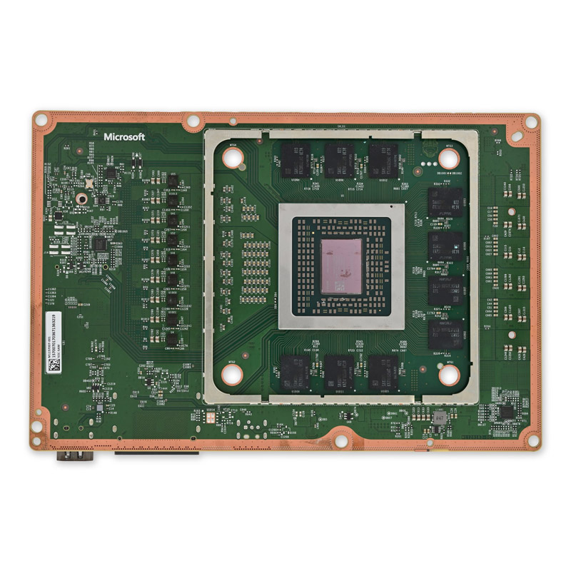
– Pop that motherboard straight up and off the heatsink to get it out of there.
– While putting things back together, carefully drop the board onto the heatsink with the APU facing down. Remember, there’s exposed thermal paste on the bottom of the board, so use those alignment pegs to get it right. If you need to move the board, it might smear the thermal paste.
Tools Used
Step 48


– Take a moment to inspect the thermal putty—it’s hanging out on the heatsink and/or the motherboard.
– If you spot any bits that are cracked or have turned into a dried-up mess, follow the next four steps to give them a fresh start.
– If you’re just swapping out the thermal paste, feel free to jump ahead to this step.
Step 49


Take it slow and steady—there might be tiny, sneaky components hiding under the thermal pad. Move carefully so you don’t accidentally knock anything loose.
– Grab your trusty spudger and gently use the flat end to scrape away that worn-out thermal pad. It’s like giving your device a little spa treatment!
Tools Used
Step 50


When you’re working close to those tiny resistors, grab some cotton swabs instead. They’re your best buddies for this job!
– Grab some isopropyl alcohol (>90%) and a lint-free microfiber cloth to wipe away any thermal putty residue. Your device will thank you for the spa treatment!
Tools Used


Step 51


To keep that thermal putty from becoming a sticky situation for your fingers, why not throw on some nitrile gloves?
– Snag yourself a small chunk of thermal putty. Take a peek at the size of the thermal pad you’re swapping out to gauge how much you’ll need.
Step 52
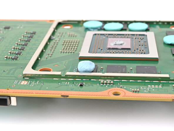

When you pop that heat sink back on, the thermal putty will squish and spread out like a champ, forming a perfect seal.
– Shape the thermal putty into a nice round ball—think stress-relief therapy but for your repair project.
– Position the thermal putty exactly where the damaged thermal pad used to be. Make sure it’s perfectly aligned over the component—like a memory chip in this case.
– For a smooth finish, you can use the flat end of a spudger or an included applicator to gently spread the thermal putty over the component’s surface. Optional, but oh-so-satisfying!
Tools Used
Step 53


When you’re working near those tiny resistors, swap out your tools for cotton swabs—they’re gentler and just what the doctor ordered for precision.
– Add a few drops of isopropyl alcohol (over 90%) to the processor, and grab a coffee filter or a lint-free cloth to give that residue a quick wipe-off. Easy peasy!
Tools Used
Step 54


Time to get that thermal paste off the heat sink! If it’s all dried out, don’t worry – just grab a spudger and gently scrape it away. Easy peasy!
– Give that thermal paste on the heat sink some love just like you did before!
Tools Used
Step 55


– To put your device back together, just follow these steps in reverse—easy peasy!
– Got e-waste? Make sure to drop it off at an R2 or e-Stewards certified recycler. Mother Earth will thank you.
– Repair not quite going your way? Don’t sweat it! Try some basic troubleshooting, or swing by our Answers community for some friendly advice.
–
Success!