How to Replace USB-C Ports on MacBook Pro 14 Late 2023
Duration: 45 minutes
Steps: 66 Steps
Heads up, tech whiz! Make sure you’ve got your tools ready and your workspace clear. It’s time to dive into this repair with some good vibes and a sprinkle of fun!
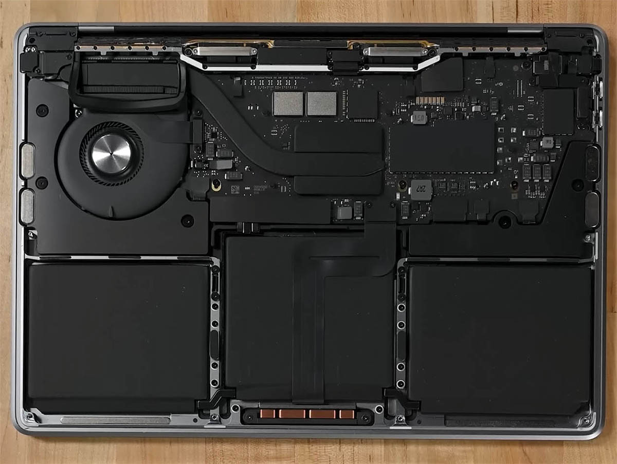
Ready to breathe new life into your MacBook Pro 14″ from late 2023 with fresh USB-C ports? Whether it’s one port or all of them, this guide’s got you covered. Don’t worry if the pictures look a bit off—they’re from a similar model, but everything should line up just right for your port swapping adventure!
Step 1


– Alright, let’s power down your MacBook, flip its world upside down while keeping the lid shut tight. No peeking until we’ve said goodbye to that battery connection!
– Detach the MagSafe cable and any gadgets hitching a ride with your MacBook.
Step 2


Before diving in, make sure your MacBook Pro is completely powered off and unplugged. Close the clamshell, flip it over and let’s get cracking!
As you dive into this repair, keep a keen eye on each screw and make sure every piece finds its way home to the same spot it came from. This will keep your gadget happy and healthy!
– Grab your P5 Pentalobe driver and unscrew those eight screws holding the lower case like a boss!
Step 3


– Slap a suction cup near the front edge of the lower case, right between those pesky screw holes.
– Give that suction handle a hearty tug to pry open a sneaky little gap under the lower case.
Tools Used

Step 4


– Pop an opening pick into the space you’ve just created.
– Wiggle that pick around the closest corner and cruise it up halfway along the side of your MacBook Pro.
Step 5


– Now, let’s do that magic on the other side too! Grab your opening pick and gently release the second clip. It’s like setting free a tiny digital fairy!
Step 6


The back edge of your MacBook features some sassy sliding clips that might require a bit of muscle to separate—think about sporting some gloves to fend off any sharp attitudes from the lower case edges.
– Gently wiggle the lower case away from the back edge, one corner at a time, to free the sneaky sliding clips.
Step 7


– Pop off that lower case like a pro!
– Slip the lower case back on when you’re ready to wrap things up!
Step 8


– Slide away any tape hanging out over the battery board data cable connector on the logic board. Let’s keep it neat!


Step 10


– Slide out the battery board data cable from its cozy home on the logic board to disconnect it.
Step 11

Your MacBook might play hard to get with some Torx Plus screws, but don’t worry, your standard Torx bits got this. Just keep the pressure steady and straight to avoid any screwy surprises!
– Grab your T3 Torx driver and whisk away those two tiny 2.1 mm-long 3IP Torx Plus screws that are holding the trackpad cable bracket snug to the logic board. It’s like unlocking a little secret compartment!


Step 13


To snap these press connectors back into their happy place, just line them up and give a gentle click on one side, then swing over and do the same on the other. Remember, no squishing the middle—those pins are delicate and don’t take kindly to being bent!
– Grab the flat end of your spudger and gently pop open the trackpad cable’s press connector that’s chilling on the logic board.
Tools Used
Step 14


The trackpad cable is gently attached to the frame. If you need help, you can always schedule a repair.
Step 15


– Gently peel away any tape that’s hiding the battery board data cable connector. Look under the giant pancake screw, that’s where the party is at!


Step 19

– Grab your T5 Torx driver and unscrew the 3.8 mm 5IP Torx Plus wide-head screw holding down the battery power connector. Easy peasy!
Step 20


Pop that connector up just enough so it won’t sneak back and reconnect while you’re working—aim for no more than a cheeky 45-degree angle to avoid any hinge hijinks!
To boost your safety game, toss a barrier, like a piece of a playing card, between the connector and board. It’s a nifty trick!
– Grab the flat end of your spudger and give that battery connector a gentle lift off the battery board to unplug the juice. Disconnecting the power like a boss!
Tools Used
Step 21


– Grab your T3 Torx screwdriver and get ready to zap out those three 2.1 mm screws holding down the antenna board bracket and the coaxial cable cover. Let’s keep things snappy and the frame secure!
Tools Used

Step 22


– Grab your tweezers or just use your fingers to playfully pluck off the cover sitting atop those snazzy antenna bar’s coaxial cables.
Step 23


– Grab your spudger and gently lift to disconnect the antenna bar’s coaxial cable.
– Do the same for the remaining two cables.
– When putting it back together, reconnecting these can be a bit fiddly. Position each connector right above its socket and press down with your spudger’s flat end. You should hear a satisfying ‘click’ when it snaps into place.
Tools Used
Step 24


– Grab your T3 Torx driver and show those four 2.1 mm screws who’s boss by removing them from the screen cable covers.
Step 25


– Grab your tweezers or just use your fingers to whisk away those two cheeky screen cable covers off the logic board.
Step 26


– Grab your trusty spudger and gently lift up to disconnect the right-most screen cable connectors chilling on the logic board. Easy does it, champ!
Tools Used
Step 27


Watch out! Steer clear of the surface-mounted buddies near the press connector when you pry—no need to startle them!
– Now, just like you did before, disconnect the next press connector found at the top left of the logic board. You’re doing great!
Step 28


– Whip off any tape hiding that sneaky microphone cable connector.


Step 30


– Slide the microphone cable out of its cozy little home on the logic board. Just like that, you’re one step closer to being a tech wizard!
Step 31


– Grab your T3 Torx driver and unscrew those nine 2.1 mm screws that are keeping the right cable covers snug against the frame!
Step 32


– Grab your tweezers or just use your fingers to jazzily remove those five right cable covers.
Step 33


– Gently peel away any tape that’s keeping the right speaker cable out of sight.


Step 35


– Slide the right speaker cable out of its socket on the logic board like you’re pulling a magic trick. Voila!
Step 36


– Grab your spudger and gently pop off the headphone jack’s press connector like a pro.
Tools Used
Step 37


– Grab your spudger and gently pop off the right USB-C ports’ press connectors like a boss.
Tools Used


Step 40


– Grab your T3 Torx driver and show those four screws on the left cable covers who’s boss! Unscrew them from the frame and keep the groove going!
Step 41


– Grab your tweezers or just use your fingers to whimsically whisk away those two pesky left cable covers.
Step 42


– Gently peel any tape hiding the left speaker cable. Let’s free that cable!


Step 44


– Slide out the left speaker cable from its cozy nook on the logic board. It’s a piece of cake!
Step 45


– Grab your spudger and gently pop off the left USB-C port’s press connector like a pro.
Tools Used
Step 46


The Touch ID sensor cable loves sticking to the frame like a koala to a tree! If that sticky adhesive won’t budge when you pop the press connector, just shimmy an opening pick beneath the cable to give it a gentle nudge.
– Grab your spudger and gently pry up to disconnect the Touch ID sensor’s press connector located near the top left corner of the device. Easy peasy!
Tools Used
Step 47


– Gently lift any tape hiding the connectors for the keyboard and its snazzy backlight. It’s like uncovering hidden treasure!
Step 48


– Grab your spudger and gently lift the locking flap on the ZIF connectors for those keyboard cables. Like unlocking a treasure chest, but for tech wizards!
Tools Used
Step 49


– Slide out those keyboard and backlight cables from their cozy homes on the logic board like a boss!
Step 50


– Gently peel back any tape that’s hiding the right fan cable connector. Let’s free that connector with style!


Step 52


– Slide out the right fan cable from its cozy home on the logic board to disconnect it. Just like magic, but you’re the wizard!
Step 53


The right fan cable is just having a little cuddle with the logic board.
– Grab your tweezers and gently tug the fan cable away from the logic board. It’s just a little sticky from the adhesive, but nothing you can’t handle with a pinch and a pull!


Step 55


– Pop off the four sleek black screw covers from the logic board. It’s like uncovering hidden treasure!
Step 56


– Grab your T5 Torx driver and get ready to unleash those 11 screws holding the logic board hostage!
Step 57


– Grab your T6 Torx driver and unscrew the trio of screws that are keeping the logic board in place.
Step 58


– Wedge a spudger in between the right side of the logic board and the frame. It’s just like sticking a bookmark in your favorite novel!
– Give that spudger a little upward pry to pop the logic board free from its snappy clips. It’s like unlocking a treasure chest!
Tools Used
Step 59


– Wedge a spudger between the logic board’s bottom edge and the frame.
– Give that spudger a little lever action to pop the logic board free from its snug clips.
Tools Used
Step 60


– Carefully hoist the logic board from the right side to free it from its snug pegs.
– Wiggle the logic board away from the device’s left side to unhook the HDMI and SDXC ports from their cozy slots in the frame.
– Lift off the logic board and bid it adieu!
Step 61


– When you’re putting things back together, rock these steps:
Step 62


– If you’re on a mission to swap out a specific port and want to jump straight to the action, click on the links below to teleport directly to the steps you need!
Step 63


– Grab your T5 Torx driver and unscrew the two 3.7 mm screws that are keeping the left USB-C port in place.


Step 65


If you’re just jazzing up one port, only unscrew the specific party crashers holding that port in place!
– Grab your T5 Torx driver and unscrew the four 3.7 mm screws that are keeping the right USB-C ports in place.