How to Replace Xbox Series X 2TB Galaxy Black Southbridge Board
Duration: 45 minutes
Steps: 50 Steps
Alright, champ, first things first, let’s make sure the power is off. Unplug all cables from your device. We’re ready to get this repair party started!
Alright, gamers! Let’s get this Xbox Series X (2TB Galaxy Black edition) back in tip-top shape! We’re gonna be swapping out that southbridge board, so make sure your console is completely powered down and all cables are unplugged before we get started. And hey, remember to keep those ESD safety procedures in mind while you’re working on the console, just to be safe. We don’t want any static surprises! If you need help with anything along the way, you can always schedule a repair.


Step 2


For a smoother removal, warm up the sticker with an iOpener or hair dryer—it’ll come off like a charm.
Just peel the sticker enough to uncover the hidden screw—no need to go all the way.
These stickers might look intimidating, but don’t sweat it! Microsoft can’t void your warranty as long as you’re careful. Enjoy the process!
– Grab a pair of blunt tweezers and gently lift that big sticker off the back panel to uncover the hidden second screw. You’ve got this!
Tools Used


Step 3

As you tackle this repair, make sure to keep an eye on each screw and replace it in its original spot to keep your console safe and sound. You’ve got this!
– Grab your trusty T8 Torx driver and get ready to work some magic! Carefully unscrew those two 7.4 mm-long screws holding the back panel in place, and let’s see what’s hiding inside!


Step 6


– Alright, grab that back panel at the opening you just made and give it a gentle lift. It should come right off. Don’t be shy, it wants to be free!
– When you’re putting things back together, just press along the edges of the back panel. It’ll snap right back into place. You got this!
Step 7


Slide the back panel into the groove at the top of the shell—easy peasy!
– Gently lift the back panel from the top edge and wiggle it free from the shell—it’s like giving it a little nudge to freedom.
– Now, go ahead and remove the back panel. You’ve got this!
Step 8

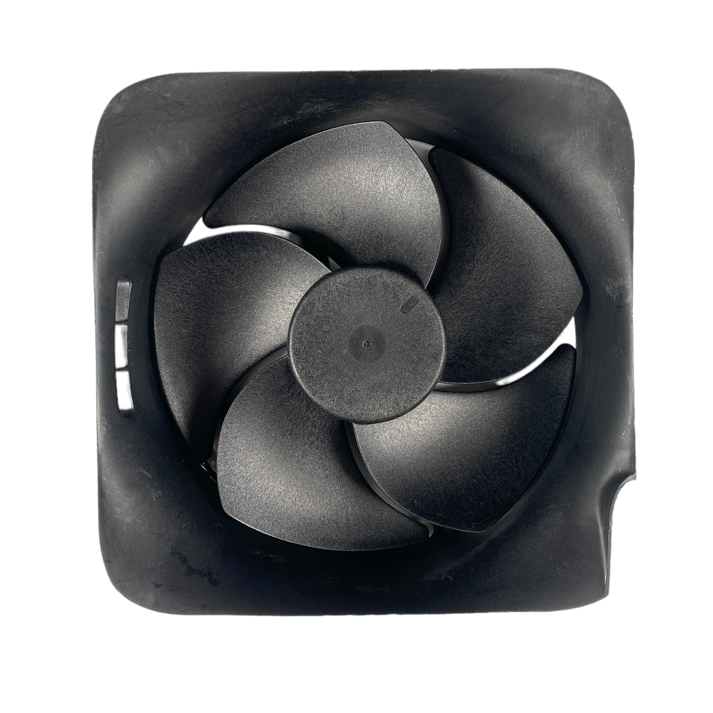
– Grab your trusty T8 Torx driver and let’s get those three screws out of the way that are keeping the fan snug in the center chassis:
– One 10.5 mm pancake screw
– Two 8.8 mm screws
Step 9


Always grab those cables by their connectors, not by the wires. Treat them with care, and they’ll treat you right!
– Gently grip the edges of the fan cable connector with your fingers or a trusty pair of blunt tweezers, and pull it upwards to disconnect it from the center chassis. Easy peasy!
– When it’s time to put everything back together, make sure to guide the fan cable snugly beneath its little cable guide on the fan housing. This way, it won’t cramp the style of your back panel.
Tools Used
Step 10


Heads up! If you’re swapping out the fan, keep in mind that the new one might not come with the plastic installation bracket. It’s usually attached to the fan with four T10 Torx screws. Just a little detail not shown in this guide. If you need help, you can always schedule a repair.


Step 12


Keep that locking tab open while you gently get the base going. You’ve got this!
Once everything is locked in, the ‘Hello from Seattle’ line will be perfectly aligned with the sides of your device. Nice work!
– Grab the base and give it a little counterclockwise twist to free it from its shell.
– Now, gently remove the base.
– When you’re putting it back together, just drop those base tabs into their little holes on the shell and twist clockwise until it clicks into place. Super easy!
Step 13


– Grab your trusty T8 Torx driver and let’s get those two 8.8 mm screws out of the way! You’ll find one securing the optical drive’s vibration isolator on the base and another on the top. Time to show those screws who’s boss!
Step 14


The vibration isolator gives a snug hug to the sides of the optical drive with its comfy silicone pads. To get it off, just give it a gentle wiggle and ‘walk’ it off the drive, one side at a time. You’ve got this!
– Gently lift the optical drive’s vibration isolator to set it free.
– When you’re putting things back together, just make sure to press the vibration isolator down snugly around both edges of the optical drive, so it sits nice and flush with the rest of the center chassis.
Step 15


Always grab those cables by their connectors, not the wires! Keep it cool and gentle, just like a pro.
– Grab a pair of blunt tweezers and gently hold onto the edges of the optical drive power connector. Now, give it a little lift to disconnect it from the optical drive. You’ve got this!
– Next, use your fingers to carefully pull up the data cable from the optical drive and disconnect it. Easy peasy!
Tools Used
Step 16


If the drive isn’t lined up just right, the top vibration isolator will be a bit shy about fitting in, and the disc reader might end up looking a little off-kilter with the front of the console.
– Grab the top edge of the optical drive and gently pull it out of its cozy spot in the shell. It’s time for a little extraction!
– When you’re putting things back together, make sure to line up the pegs on the bottom edge of the optical drive with the guide holes on the shell’s bottom. It’s like a puzzle piece fitting right in!
Step 17


Handle those ribbon cables and their connectors with care—they’re delicate! Gently flip the locking tabs and ease the cables out slowly. You’ve got this!
– Use the flat end of a spudger to carefully flip open the metal locking tab on the USB port ribbon cable. It’s just like opening a tiny treasure chest!
– When you’re putting everything back together, gently snap the metal locking tab back into place once the cable is inserted. Think of it as giving your device a little high five!
Tools Used
Step 18


Give that pull tab a good tug, but remember, it’s a tab, not the cable!
If the USB port cable feels stuck to the metal chassis, gently warm it up with a hairdryer or a heat gun. Depending on the model of Xbox, you might also need to slip an opening pick under the cable to break the adhesive bond.
– Gently grab the black plastic pull tab with your trusty tweezers and give it a little tug to free the USB port cable. You’re on the right track!
Tools Used
Step 19


Give that pull tab a gentle tug, but don’t go yanking on the cable itself!
Remember, always press down on the metal tab before pulling the cable. Skip that step and you might just end up with a damaged cable or connector. Let’s keep things smooth!
– Grab your trusty spudger and gently press down on that little metal tab next to the power button cable’s board connector. You’ve got this!
– With the tab pressed down, take a pair of tweezers and give that pull tab a little tug to disconnect the power button cable from the center chassis. Easy peasy!
– When you’re putting everything back together, just slide the cable in and listen for that satisfying little ‘snap’ as it clicks into place. You’re doing great!
Step 20

– Grab your trusty T8 Torx driver and unscrew the three 7.4 mm screws holding the center chassis assembly to the shell. Easy peasy!
Step 21


Depending on your Xbox model, the sticky stuff might be hiding on the underside of the cable. If that’s the case, grab an iOpener or a hair dryer and give that cable a little warmth.
– Alright, now it’s time to give that USB port ribbon cable a little love! Gently peel it away from the heatsink. We’re almost there!
Tools Used
Step 22


The central chassis fits snugly with the shell thanks to some handy guide pegs. To get that chassis out, you’ll need to slide those pegs free from their slots. Easy peasy!
– Grab the center chassis and give it a gentle tug towards the green fan grille at the top of the shell. You’ll hear those guide pegs uncoupling – it’s like a little victory dance!
– Now, carefully lift out the center chassis assembly. You’re almost there!
– During reassembly, keep an eye on those ribbon cables. Make sure they’re not getting pinched as you lower the center chassis back into the shell. If you need help, you can always schedule a repair
Step 23


– Detach the chassis strap from the right side of the power supply with a little flair!
Step 24


– Gently tug the chassis strap and slide it off the power supply like a pro.
– With the strap free, tuck the loose end aside neatly—you’ve got this!
Step 25

– Grab your trusty T8 Torx driver and let’s tackle those three screws holding the power cable port snugly in place:
– Two screws are 13.1 mm in size, just the right fit!
– And don’t forget about the one 35 mm screw, it’s part of the crew too!
Step 26


– Gently pop the power connector out of its cozy little spot in the chassis.
Step 27


– Pop open the lid on the power cable’s plastic guide with a gentle nudge.
Step 28


– Gently free the power cable from its cozy spot under the extra cable guide section. Easy does it!
Step 29

– Grab your trusty T8 Torx driver and unscrew that 8.8 mm screw holding down the power supply corner cover. You’ve got this!


Step 31

– Grab your trusty T8 Torx driver and let’s get to work! Carefully unscrew those three 9.6 mm screws that are holding the accessory antenna board snugly to the center chassis. You’ve got this!
Step 32


– Grab the antenna board and gently pull it straight out from the center chassis to disconnect it. You’ve got this!
– When putting everything back together, make sure to line up the board’s connector with the port on the center chassis, then give it a firm press to reconnect. Easy peasy!
Step 33

– Grab your trusty T8 Torx driver and let’s tackle those nine screws holding the board shield in place:
– Six sleek 8.8 mm black screws
– Two shiny 35 mm silver screws
– One petite 13.1 mm silver screw
Step 34


– Gently lift the board shield away from the center chassis. You’ve got this!
Step 35


– Unhook the chassis strap from the locking tabs on both sides of the power supply. You’ve got this!
Step 36


– Time to say goodbye to that chassis strap! Just gently remove it and you’re on your way to a smooth repair journey.
Step 37


Remember, pull on the connector, not the cable itself. It’s like a good friend, treat it with care!
– Give that 10-pin power connector’s locking tab a firm squeeze to release its grip.
– Keep holding that tab down and gently lift the connector straight up to free it from the board. Easy does it!
Step 38


– Give that locking tab on the 2-pin power connector a gentle squeeze to keep it secure. No need to rush!
– While you’re holding that tab down, simply lift the connector straight up to detach it from the board like a pro.
Step 39


– Lift the lid on that plastic cable guide for the power supply and let the magic begin!
Step 40


– Grab your trusty T8 Torx driver and let’s get those four screws out! They’re holding the power supply tight, and we need to set it free. Here’s what to look for:
– Three shiny 35 mm silver screws that are just waiting to be removed.
– One sneaky 8.8 mm black screw, playing hard to get.
Step 41


– Alright, champ, let’s start by giving that power supply the boot! Disconnect it and get ready to rock and roll!
Step 42

– Grab your trusty T8 Torx driver and let’s get to work! Carefully unscrew those three 8.8 mm screws holding the Wi-Fi antenna board in place. You’ve got this!
Step 43


Hey there! Hold onto that antenna board, alright? Give it a little wiggle and make sure it’s totally disconnected before you go pulling it up. We want to keep those wires happy!
– Grab the antenna board and gently pull it straight out from the center chassis to disconnect it.
– Set the antenna board aside.
– When putting it back together, line up the board’s connector with the port on the center chassis and give it a firm press to reconnect. If you need help, you can always schedule a repair.
Step 44


Hey, depending on your Xbox model, the cable lock tab might be in the middle. No worries, just skip to the next step if that’s the case.
Alright, with those tabs pushed down, the cable should slide out pretty easy. You got this!
– Grab the base of the interconnect cable connector with your fingers—no tools needed, just your trusty hands!
– Press down on both sides of the connector to release those sneaky locking tabs. They’ll pop right open!
– With the tabs down, hold the edges of the interconnect cable and gently pull it straight out. Easy does it!
– When putting it back together, slide the cable in until you hear that satisfying ‘snap’—that’s how you know it’s locked in place. If you’re stuck, you can always schedule a repair.
Step 45


– Let’s get that connector out! Use your fingers to gently pinch the locking tab in the center of the interconnect cable connector.
– While pinching the tab, insert the flat end of a spudger between the top of the socket and the connector’s tab. It’s like a little dance, see?
– Twist the spudger to lift the connector out of its socket until the clip in the center pops loose. You’re doing great!
– Now, pull the connector straight up and out of its socket. You got this!
– Time to put it back together! Insert the interconnect cable connector into its socket and press down on both edges until the connector clicks into place. You’re a pro!
Tools Used
Step 46

– Alright, grab that T8 Torx driver and let’s loosen those seven 8.8 mm screws holding down the southbridge board shield. It’s like a little party for your tools!
Step 47


– Gently lift the center chassis away from the motherboard and heatsink assembly, like you’re unveiling a surprise!
– As you do this, make sure to guide the interconnect cable through the cutout on the center chassis. It’s like giving it a little path to follow!
Step 48


– It’s time to get your hands a little dirty! Go ahead and take off that board shield.
Step 49


– Time to give that power supply cable guide a little lift! Gently remove it from the southbridge board. You got this!
Step 50


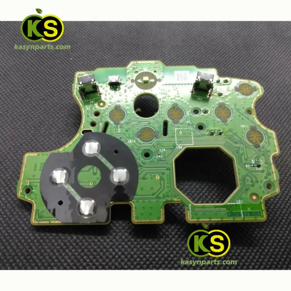
– Time to get that southbridge board out of the chassis! It’s hanging out in the middle, so give it a gentle nudge. We’re all about respect, even for tiny components.
– Now, take a peek at your new southbridge board. Does it come with power and data cables already attached? If it doesn’t, no worries! Just gently remove them from the old board and give them a warm welcome on the new one.
Success!