How to Replace Xbox Series X Motherboard DIY Guide
Duration: 45 minutes
Steps: 52 Steps
Let’s power down and unplug those cables, folks!
Ready to dive into some Xbox Series X magic? This guide is your go-to for swapping out that motherboard and also gives you the scoop on reapplying thermal paste. Before we get started, make sure your console is totally powered down and all cables are unplugged. And hey, don’t forget to keep it safe by following those electrostatic discharge (ESD) safety steps while you’re at it! If you need help, you can always schedule a repair.
Step 1


Alright, before you dive in, make sure to power down your console completely and unplug all those pesky cables. Safety first!
– Grab those tweezers and carefully peel off the sticker that’s covering the first screw on the back panel, right by the base. You’re on your way to a successful repair!
Tools Used

Step 2


For a smoother sticker peel, grab an iOpener or a hair dryer to warm it up a bit.
Just peel back the sticker enough to reveal the hidden screw—no need to take it all the way off!
Sure, these are tamper-evident stickers, but relax! Microsoft can’t void your warranty as long as you keep everything intact. Enjoy the process!
– Grab a pair of blunt tweezers and gently lift that big sticker off the back panel. It’s hiding the second screw, and we need it to keep moving forward!
Tools Used


Step 3

As you dive into this repair, keep an eye on every little screw. Remember, each one has its special spot, so put it back where it belongs to keep your console safe and sound.
– Grab your trusty T8 Torx driver and get ready to tackle those two 7.4 mm-long screws holding the back panel in place. You’ve got this!
Step 4


– Slide the flat end of a spudger into the little gap between the back panel and the shell, just to the left side of the base. You’ve got this!
– Gently pry up the back panel to pop it free from those sneaky locking clips. Easy peasy!
Tools Used

Step 5


– Slide the flat end of your trusty spudger into the little gap between the back panel and the shell, just to the right side of the base.
– Gently lift up that back panel to pop it free from the locking clips. You’ve got this!
Tools Used
Step 6


– Grab the back panel at the opening you just made and gently pull it up and away from the shell to release those long edges.
– When putting it all back together, give a little press along the edges of the back panel to lock it in securely.
Step 7


The back panel fits snugly into the groove at the top of the shell. If you need help, you can always schedule a repair
– Gently tilt that back panel upwards and give it a little tug away from the top edge of the shell to pop it out of its snug spot.
– Now, just lift off the back panel and set it aside.
Step 8

– Grab your trusty T8 Torx driver and let’s tackle those three screws holding the fan snugly in the center chassis:
– One 10.5 mm pancake screw, ready to be removed!
– Two 8.8 mm screws that are just waiting for you to unscrew them!
Step 9


Hey there! Remember to give those cables a gentle tug by their connectors, not the wires. Your gear will thank you for it!
– Gently grab the edges of the fan cable connector with your fingers or some trusty blunt tweezers, and give it a little lift to disconnect it from the center chassis. Easy peasy!
– When putting everything back together, make sure to guide the fan cable snugly underneath its small cable guide on the fan housing. This way, it won’t get in the way of the back panel. You’ve got this!
Tools Used
Step 10


When swapping out the fan, keep in mind that your new fan might not come with the plastic installation bracket. That little piece is usually attached to the fan with four T10 Torx screws. Just a heads up, it’s not shown in this guide! If you need help, you can always schedule a repair.
– Gently slide the fan out of its cozy slot to free it up.
– When you’re putting it back in, remember: the fan has a special way to fit—make sure Master Chief is facing you, and you’re all set!
Step 11


– Grab the flat end of your trusty spudger and gently lift the locking tab that’s securing the base to the shell. You’ve got this!
Tools Used
Step 12


Hold that locking tab open while you get the base going—you’re almost there!
When everything’s locked in, that ‘Hello from Seattle’ line will sit pretty parallel to your device’s sides.
– Grab the base and give it a gentle twist to the left to free it from the shell.
– Take out the base with ease.
– When putting it back together, align those base tabs with their cozy spots in the shell and twist to the right until you hear it click into that snug interior locking tab.
Step 13


– Grab your trusty T8 Torx driver and get ready to take action! You’ll want to remove those two 8.8 mm screws that are holding the optical drive’s vibration isolator snugly to the shell. One screw is hanging out on the base, while the other is chilling on the top of the isolator. You’ve got this!
Step 14


The vibration isolator gives a snug hug to the sides of the optical drive with its silicone pads. To gently ease it off, just give it a little ‘walk’ to slide it off each side.
– Gently lift the optical drive’s vibration isolator to remove it.
– When putting things back together, just make sure to press down on the vibration isolator and tuck it around both edges of the optical drive. It should fit snugly with the rest of the center chassis.
Step 15


When handling cables, remember to give a gentle tug on the connectors, not the wires themselves!
– Grab a pair of blunt tweezers and gently pinch the edges of the optical drive power connector. Give it a little tug upwards to disconnect it from the optical drive.
– Now, use your fingers to give a light pull and free the data cable from the optical drive.
Tools Used
Step 16


If the drive isn’t lined up just right, the top vibration isolator will have a tough time fitting in, and the disc reader might not align perfectly with the console’s front. Just keep an eye on that alignment! If you need help, you can always schedule a repair.
– Grab the top edge of the optical drive and give it a gentle pull to slide it out of its cozy home in the shell. You’ve got this!
– When it’s time to put everything back together, make sure to line up the pegs on the bottom of the optical drive with the guide holes waiting for them on the shell. Easy peasy!
Step 17


Handle those ribbon cables and their connectors with care, folks! They’re delicate little things. So, remember to gently ease open those locking tabs and take your time when pulling the cables out. You’re doing great! If you need help, you can always schedule a repair.
– Grab that trusty spudger and gently nudge the flat end to pop open the metal locking tab on the USB port ribbon cable. You’ve got this!
– When it’s time to put everything back together, just ease the metal locking tab back into place after you’ve slid in the cable. Easy peasy!
Tools Used
Step 18


Only tug on the pull tab—leave the cable alone, it’s not a tug-of-war!
If the USB port cable seems a bit too cozy with the metal chassis, give it a little warmth with an iOpener or hair dryer. Depending on your Xbox model, you might also want to slide an opening pick underneath the cable to help break that adhesive bond. Keep it cool and take your time—you’re doing great!
– Grab your trusty tweezers and gently lift the black plastic pull tab to free that USB port cable. You’ve got this!
Tools Used
Step 19


Gently tug on the pull tab, but leave the cable alone – you’re not trying to play tug-of-war here!
Remember to press that little metal tab before yanking on the cable. Skip this step, and you might end up giving the cable or connector a bad day!
– Grab your trusty spudger and gently press down on the metal tab next to the power button cable’s connector. You’ve got this!
– Once that tab is down, take a pair of tweezers and gently tug on the pull tab to disconnect the power button cable from the center chassis. Easy peasy!
– When it’s time to put everything back together, the cable should click into place with a light ‘snap’—just like a puzzle piece fitting in!
Step 20

– Grab your trusty T8 Torx driver and let’s get to work! Unscrew those three 7.4 mm screws that are holding the center chassis assembly snugly against the shell. You’ve got this!
Step 21


Depending on your Xbox model, you might find the adhesive hanging out on the cable’s underside. If that’s the case, grab an iOpener or a hair dryer to give that cable a little warmth.
– Carefully lift the taped USB port ribbon cable off the heatsink like you’re unveiling a surprise gift!
Tools Used
Step 22


The center chassis is snugly positioned with the shell thanks to some handy guide pegs. Just slide those pegs out of their cozy slots, and voilà, the chassis is ready to be lifted out!
– Give the center chassis a nice grip and gently pull it towards the cheerful green fan grille at the top of the shell, disconnecting those guide pegs like a pro!
– Carefully lift out the center chassis assembly and remove it from the shell with confidence.
– When putting everything back together, keep an eye out to ensure those ribbon cables don’t get squished as you lower the center chassis into the shell.
Step 23


– Release the chassis strap from the right side of the power supply. You’ve got this!
Step 24


– Gently lift the chassis strap off the power supply, like you’re peeling a banana. No need to rush!
– Once you’ve got that strap free, just set the loose part aside. You’re doing great!
Step 25

– Grab your trusty T8 Torx driver and let’s tackle those three screws holding the power cable port snugly to the chassis!
– You’ll need to remove two screws that are 13.1 mm in length.
– Don’t forget about that one 35 mm screw; it’s just as important!
Step 26


– Gently pop the power connector out of its cozy little home in the chassis.
Step 27


– Gently unhook the lid on the power cable’s plastic guide and lift it open like a champ!
Step 28


– Gently pull the power cable out from beneath the bonus section of the cable guide, and you’re one step closer to a smooth repair!
Step 29

– Grab your trusty T8 Torx driver and get ready to rock! Carefully unscrew the 8.8 mm screw that’s holding down the power supply corner cover. You got this!
Step 30


Depending on your Xbox model, you might not have this cover. No worries, though!
– Grab your trusty fingers or a pair of tweezers, and gently lift off that power supply corner cover like a pro!
Tools Used
Step 31

– Grab your trusty T8 Torx driver and carefully unscrew those three 9.6 mm screws holding the accessory antenna board snugly in the center chassis. You’re doing great! If you need help, you can always schedule a repair.
Step 32


– Hold onto that antenna board and gently pull it straight out from the center chassis to disconnect it. You’ve got this!
– When putting things back together, make sure to line up the board’s connector with the port on the center chassis and give it a nice press to reconnect. Easy peasy!
Step 33

– Grab your trusty T8 Torx driver and get ready to tackle those nine screws holding the board shield in place:
– Six sleek 8.8 mm black screws
– Two shiny 35 mm silver screws
– One unique 13.1 mm silver screw
Step 34


– Gently lift the board shield to pop it free from the center chassis. You’re doing great!
Step 35


– Unplug that chassis strap from the locking tabs on both sides of the power supply. You got this!
Step 36


– Time to say goodbye to the chassis strap! Just gently remove it and keep moving forward with your repair journey.
Step 37


Always grab those cables by their connectors, not the wires! Your tech will thank you for it!
– Give that locking tab on the 10-pin power connector a gentle squeeze and hold on tight!
– While you’re holding it down, lift the connector straight up to free it from the board. You’ve got this!
Step 38


With the locking tabs pressed down just right, the interconnect cable should slide out with minimal effort.
– Grab the base of the interconnect cable connector with your fingers, just like you’re about to pull off a magic trick.
– Press down on each side of the connector to release those sneaky cable locking tabs.
– With the tabs pressed down, hold onto the edges of the interconnect cable and gently pull it straight out of the connector to disconnect it. Easy peasy!
– When you’re putting it all back together, listen for that satisfying ‘snap’ as the interconnect cable clicks into place when fully inserted.
Step 39


– Grab your trusty T8 Torx driver and carefully unscrew those three shiny 35 mm-long silver screws from the power supply—just leave that fourth black screw where it is, no need to disturb it!
Step 40


– Gently grab the edges of the center chassis (just avoid the power supply) and lift it away from the motherboard and heatsink assembly, making sure to route that interconnect cable through its little cutout.
Step 41


The SSD shield comes with thermal pads on both sides, so let’s keep those little guys safe and sound during this process!
– Grab your trusty spudger and gently lift the edges of the metal SSD shield. You’ve got this!
– Now, go ahead and take off that SSD shield. Easy peasy!
Tools Used
Step 42

– Grab your trusty T8 Torx driver and go ahead and unscrew that 5.2 mm screw holding the SSD in place. You’ve got this!
Step 43

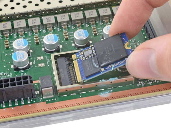
Once you’ve unscrewed the SSD screw, the SSD will gracefully pop up at a slight angle, ready for its next move!
– Grab the end of the SSD and gently pull it away from its M.2 board connector to set it free.
– When you’re putting it back together, slide the SSD in at a slight angle into its board connector, then secure it in place with the SSD screw, making sure it’s nice and snug.
Step 44


Got a locking tab on your interconnect cable? Just breeze right past this step and move on!
When you press those locking tabs down just right, your interconnect cable should slide out like it’s on a smooth ride. Easy peasy!
– Give that interconnect cable connector a gentle squeeze at the base with your fingers.
– Press down on each side of the connector to release those sneaky cable locking tabs.
– With the tabs happily depressed, take hold of the edges of the interconnect cable and pull it straight out to disconnect it like a pro.
– Say goodbye to the interconnect cable as you remove it.
– When putting things back together, listen for that satisfying ‘snap’ as the interconnect cable clicks into place when fully inserted.
Step 45


– Give that locking tab on the interconnect cable a gentle pinch and slide the flat end of your trusty spudger in to pop that clip loose.
– Now, with a little finesse, pull the connector straight up and out of its cozy socket.
– When it’s time to put everything back together, align the #1—SOC side of the interconnect cable connector into its socket, making sure the locking tab is peeking out. Then, just press down on the edges until you hear that satisfying snap!
Tools Used
Step 46


Handle with care! We want to keep all those little components around the metal shield safe and sound.
– Grab that trusty spudger and use its flat end to gently lift up the edges of the big metal shield sitting right in the heart of the motherboard. You’ve got this!
Tools Used
Step 47


– Time to say goodbye to that metal shield! Give it a gentle nudge and remove it with care.
– When you’re putting everything back together, make sure to place that shield just right and give it a solid push all around the edges to keep it snug and secure.
Step 48


When it comes to loosening and tightening those APU tension bracket screws, remember to take it slow and steady! Work in an “X” pattern, like so: top left → bottom right → top right → bottom left. A little at a time goes a long way!
– Grab your trusty T8 Torx driver and let’s tackle those four APU tension bracket screws, each measuring 12.3 mm long. You’ve got this!
Step 49


Avoid wiggling that APU bracket like a dance move! You might just upset those delicate components hiding underneath. Remember, it’s all about lifting straight up with confidence!
– Gently lift the APU bracket straight up using your fingers and take it off with care.
– When putting everything back together, make sure to align the bracket properly. The black plastic sides should be facing the long edges of the motherboard. The piece of plastic with the circular hole (not the oblong one) needs to be closer to the interconnect cable socket. Check out this photo for a visual guide!
Step 50


If the thermal paste and putty are feeling a bit clingy, your board might be stuck to the heatsink assembly. No worries! If it’s giving you a hard time, grab a spudger and gently lift the edges of the board to ease it apart. Remember, if you need help, you can always schedule a repair.
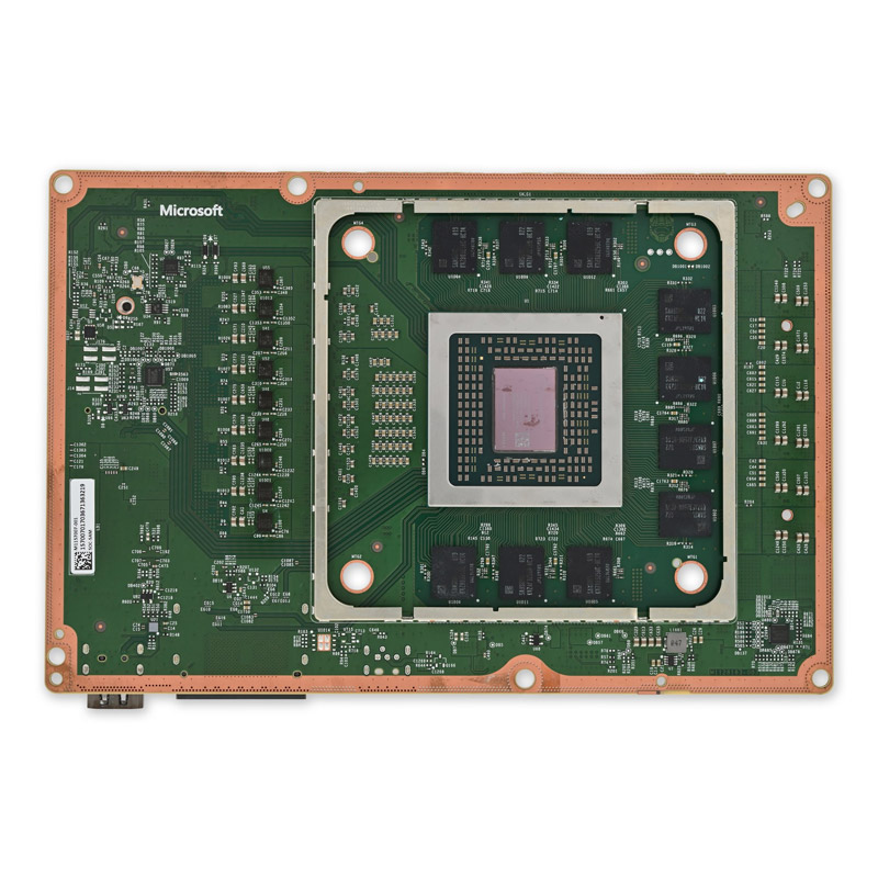
– Gently lift the motherboard straight up and off the heatsink to release it.
– When putting it back together, make sure to place the board onto the heatsink with the APU side down. Keep in mind, the thermal paste on the underside of the board is exposed, so line it up with the alignment pegs for a snug fit. If you need to adjust the board, just be cautious as it might smear that thermal paste.
Tools Used
Step 51
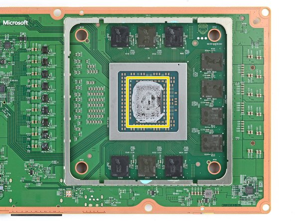
If you’re planning to give that motherboard a second chance, don’t forget to give the APU a little TLC too! And hey, to keep those tiny resistors safe and sound, grab some cotton swabs and get to work!
– Get ready to give your APU some love! Follow this guide to tidy up that heatsink and slather on some fresh thermal paste. Your device will thank you for it!
Tools Used

Step 52


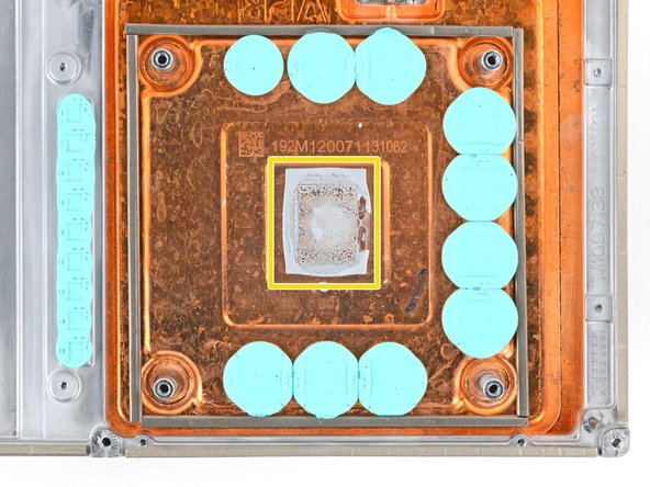
Keep an eye on where the original pieces of thermal putty are located, as well as their shape and size. When you’re ready to swap them out, make sure the new pieces match perfectly!
– First off, give that thermal putty a once-over—it should be lounging on the heatsink or the motherboard.
– If you spot any sad, damaged, or dried-out pieces, it’s time for a little makeover. Remove and replace them with some fresh options:
– Grab a spudger and gently coax those larger putty pieces off—just be super careful not to disturb anything on the board.
– Next up, let’s tidy things up! Use some isopropyl alcohol along with coffee filters or cotton swabs to wipe away all the leftover thermal putty residue.
– Finally, place new pieces of putty (not thermal paste, folks!) that match the size and shape of the originals. You’re doing great!
Tools Used