
iPad 2 GSM Volume and Power Button Cable Replacement
Duration: 45 minutes
Steps: 57 Steps
Dive into this guide to swap out the volume and power button cable assembly on your iPad 2 GSM. This assembly even includes that nifty sensor that detects the Smart Cover magnet! While some of the visuals in this guide may feature the Wi-Fi model, don't worry—your cellular model is just a bit different on the inside, but the process is still the same. Let’s get started and make that iPad feel brand new again!
Step 1


For carousel microwaves: double-check that the plate spins without any hiccups. If your iOpener gets stuck, it might overheat and cause a burn, so keep it moving!
Before you dive in, it's a good idea to give your microwave a quick clean. A layer of leftover food or grime could get cozy with the iOpener, and we don't want that! A clean microwave makes for smoother sailing.
- Pop that iOpener right in the middle of your microwave like it owns the place.
Tools Used

Step 2

Keep an eye on your iOpener and don’t let it get too hot — overheating can make it pop like a balloon! Never heat it beyond 100˚C (212˚F).
If the iOpener looks puffy or swollen, don't even think about touching it.
If the center of the iOpener is still too toasty to handle, just keep using it while it cools off a bit before reheating. When heated just right, it should stay warm for about 10 minutes.
Microwave power levels can vary, so you might need to adjust the heating time a bit. Your iOpener is ready when it’s just a tad too warm to keep your fingers on it comfortably.
- Give that iOpener a warm hug in the microwave for thirty seconds. It's like a cozy spa day for your tools!
- As you work your magic on the repair, keep that iOpener's vibe going by giving it a quick reheat in the microwave every thirty seconds. It’ll appreciate the extra warmth!
Tools Used
Step 3

The iOpener can get pretty hot, so handle it with care. If it feels too toasty, grab an oven mitt for some extra protection.
- Carefully take the iOpener out of the microwave by grabbing one of the two flat ends—steer clear of that hot middle part!
Tools Used
Step 4

Heads up! The iOpener gets seriously hot, so make sure to grab it only by the end tabs to keep your fingers safe and sound.
If you don't have a microwave handy, no worries! Just follow this step to warm up your iOpener using boiling water.
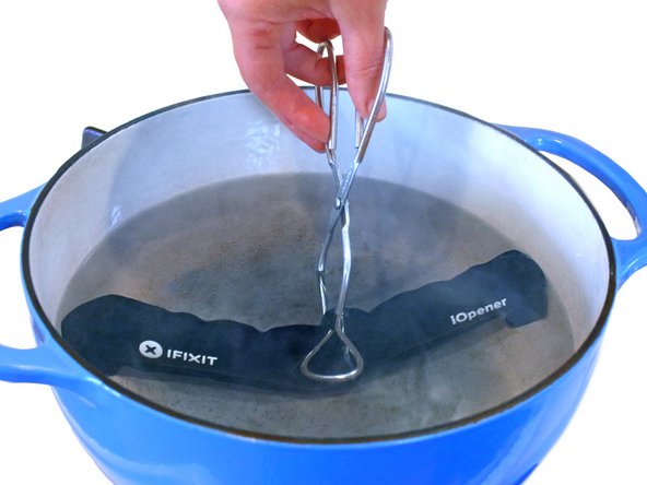
- Grab a pot or pan and fill it with enough water to completely cover your iOpener.
- Bring the water to a rolling boil, then turn off the heat—no need to keep it boiling.
- Carefully dunk the iOpener into the hot water, making sure it's fully submerged, and let it soak for 2-3 minutes.
- Use tongs to fish out the warmed-up iOpener—hot stuff, so be careful!
- Give the iOpener a good dry-off with a towel so it’s ready to work its magic.
- Ready to go! If it cools down before you’re done, just repeat the heating process: boil the water, turn off the heat, and soak the iOpener for another 2-3 minutes.
Tools Used
Step 5


Put on those safety glasses to keep your peepers safe, and be gentle with that LCD screen to avoid any mishaps!
This will keep those pesky glass shards contained and give your display some solid support while you’re prying and lifting it up. You've got this!
- If your display glass is sporting a crack, let’s keep it from shattering further and protect your hands during the repair by slapping on some tape.
- Layer on overlapping strips of clear packing tape over your iPad's display until it’s completely covered. Think of it as a protective shield!
- Now, just follow the rest of the guide as best as you can. Keep in mind, once that glass starts to break, it might get a little feisty and crack more while you work. You might want to grab a metal prying tool to help scoop out those stubborn pieces.
Step 6

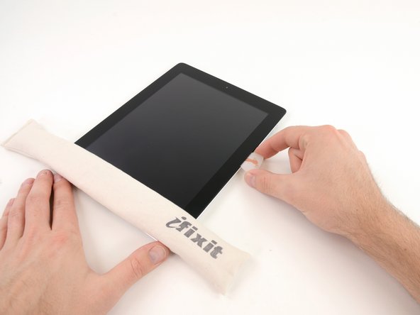
Hey there, just a quick reminder! While you're getting into the nitty-gritty of this repair, keep in mind that you might encounter some pesky broken glass. To keep your peepers safe from any unexpected flying bits, we highly recommend rocking some safety glasses. Stay safe and keep that sparkle in your eyes!
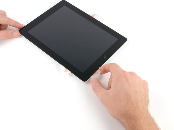
- Place the iOpener flat against the right edge of your iPad, ensuring it sits snugly so that it makes solid contact with the screen.
- Give it about 90 seconds to work its magic before you dive in and try to lift the front panel.
Tools Used
Step 7


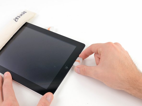
Getting the plastic opening tool's tip between the glass and plastic might need a bit of elbow grease. Take it slow and steady, and feel free to give it a little wiggle back and forth as needed. Patience is key here, but you’ve got this!
- Spot a tiny gap in the iPad’s adhesive ring at the upper right corner, about 2.0 inches (~5 cm) down from the top. This little opening is your entry point.
- Line up your plastic opening tool with the mute button. Gently slip just the tip of the tool into the crack between the front glass and the plastic bezel—just enough to nudge the gap open a bit.
Step 8

- Carefully slide your tool right where the plastic display bezel meets the front glass panel — that’s the sweet spot!
Step 9


- With the tip of your trusty plastic opening tool snugly placed between the front glass and plastic bezel, gently slide a plastic opening pick into that little gap right next to the tool. You're doing great!
Step 10


- Take that trusty plastic opening tool out of the iPad, and slide the opening pick a little deeper under the front glass, aiming for about 0.5 inches down. You've got this!
Step 11

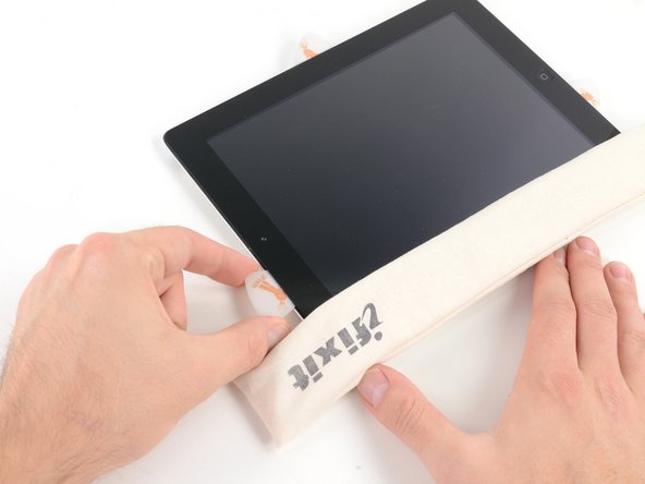
- As you're gently loosening the adhesive on the right side of the iPad, give the iOpener a quick reheat and then place it back on the bottom edge of the iPad.
Tools Used
Step 12


The adhesive really likes to stick around, so you might need to put in some elbow grease! Take it slow and steady.
If you spot the tip of the opening pick peeking out from under the front glass, give it a gentle tug. Don't worry, having the pick this deep won't cause any harm, but it might leave some adhesive goo on the LCD – and nobody likes a messy screen!
- While the bottom edge is getting some heat from the iOpener, start working your magic on the right edge of the iPad to loosen that sticky adhesive.
- Gently slide the opening pick down the edge of the iPad, carefully freeing the adhesive as you go. Take it slow and steady!
Tools Used
Step 13


As you peel away that adhesive, you might find it helpful to glide the heated iOpener back to the right edge of the iPad. Whether you need to do this or not really depends on how long your iPad has had to chill while you were busy at work.
- If your opening pick gets stuck in the adhesive, try gently "rolling" it along the edge of the iPad to keep loosening the glue and make progress smoother.
Tools Used
Step 14


- Before you pull out that first opening pick from the bottom corner, sneak a second pick under the right edge of the front glass to keep the adhesive from sticking back down.
- Reheat your iOpener and place it on the top edge of your iPad. Give it a moment to work its magic.
Tools Used
Step 15

The Wi-Fi antenna is securely fastened to the bottom right corner of the rear case with screws and a cable. Given how the antenna is positioned, take it slow and steady—one wrong move and you could accidentally damage it. Trust us, you don't want that! So, be cautious as you work on it.
- Heads up! The next few steps need you to be super careful.
- You'll need to carefully loosen the adhesive holding the antenna to the front panel without messing up the delicate connections attaching the antenna to the bottom of the iPad. Take it slow and follow these steps closely.
Step 16


Keep your pick away from the bottom right corner – it’s a no-go zone! Slide too far and you might just say goodbye to your Wi-Fi antenna. Let's keep it safe, alright?
- Gently glide that opening pick around the bottom right corner of the iPad to free up the adhesive. You're doing great!
Step 17


As you slide the opening pick along the bottom right edge of the front panel, keep an eye out! The Wi-Fi antenna is cozying up to the corner, and if you're not careful with the adhesive, it might just decide to take a vacation. Let's keep it intact, shall we?
Keep the pick snugly tucked under the front glass—don’t pull it all the way out! Leave about 1/8" (3 mm) of the tip still chilling under there to keep things steady.
- Gently slide the opening pick's tip along the bottom edge of the iPad, carefully working to release the adhesive over the Wi-Fi antenna. Keep it steady and you'll make it through in no time!
Step 18

- Alright, once you've given a little wiggle past the Wi-Fi antenna, which is about 3 inches (75 mm) from the right edge, right by the home button, it's time to slide that opening pick back in all the way like it's ready for a dip in a pool.
- Now, glide that pick to the right and watch the adhesive give way, freeing the Wi-Fi antenna from its clingy relationship with the front glass.
- Remember, the antenna is snugly held down at the bottom of the iPad with some screws and a cable. By doing this step, you're making sure the antenna breaks free from the front panel safely, so when it’s time to remove the panel, you won't have to worry about any accidental damage. Smooth sailing ahead!
Step 19


Keep the iOpener's heat game strong, but not too strong! Heat it for no more than a minute at a time, and then give it a cool-down of at least two minutes before you heat it up again. You've got this!
If the adhesive has cooled down a bit too much along the bottom edge, just give the iOpener a quick reheat to warm up that sticky goodness where you're working. Keep it cozy!
- Keep on peeling that adhesive along the bottom of your iPad! Gently pull the opening pick out far enough to glide around the home button, then pop it back in to a depth of about 1/2 inch (10 mm) once you've navigated past the home button.
Tools Used
Step 20


For iPad 4 models, carefully slip that pick in, but only up to 1/2 inch (10 mm) in this area. We want to protect that home button ribbon cable like it's a precious treasure!
- Keep peeling away that sticky stuff along the bottom edge of your iPad—every bit counts!
- Pop in the opening pick just below the front glass near the home button and let it chill there for a bit.
Step 21

- Pop the iOpener back in the microwave to warm it up, then place it on the left edge of your iPad to gently heat up the adhesive there.
Tools Used
Step 22


If the adhesive has gotten a bit too cool, no worries! Just swap in a fresh iOpener along the top edge and keep going. If your iOpener is feeling chilly, give it another heat-up and get back to work!
- Gently glide the opening pick along the top edge of your iPad, giving it a little tug to navigate around that front-facing camera bracket.
- Heads up! The adhesive in this area is super thick, so you might need to apply a bit of muscle. Just take your time and watch your step to avoid any slips that could hurt you or your iPad.
- If your opening pick starts to get stuck in the sticky stuff, try giving it a little 'roll' like we showed in step 9.
Tools Used
Step 23


If the adhesive feels nicely warmed up, go ahead and set the iOpener aside for easier access. But if it’s still sticking around like it’s not ready to quit, just heat up the iOpener again and place it back on the left edge while you keep working your magic.
- Keep peeling away that adhesive along the top edge of the iPad, and gently work the opening pick around the top left corner.
Tools Used
Step 24


The digitizer cable is hanging out about 2 inches (50 mm) from the bottom of the iPad. When you get to about 2.25 inches (60 mm) from the bottom, it's time to pause your pick action. You're doing great!
- Gently slide your opening pick along the left edge of the iPad to loosen the adhesive. Heads up—the adhesive here is pretty thin because of the digitizer running along the entire left side. Keep your pick shallow (no deeper than 10 mm or about half an inch) to avoid any accidental digitizer damage.
Step 25

Be super careful as you glide through this step! The bottom of the digitizer cable is just about 1 inch (25 mm) from the bottom of the iPad. Take your time and watch out—let's avoid cutting that cable!
- Slide the opening pick gently underneath the bottom edge of the iPad to loosen the adhesive at the bottom left corner. You've got this!
Step 26

Sometimes the adhesive around the edge of the iPad likes to play sticky again. If that happens, gently slide a pick under the spot where the glass is still holding on and carefully slice through the adhesive to free it.
- Grab one of your opening picks and gently wedge it under the bottom right corner of the iPad, then carefully lift it up and hold it with your fingers.
Step 27


Watch out for any sticky adhesive lurking around—grab an opening pick and gently slice through any glue still holding the front panel in place.
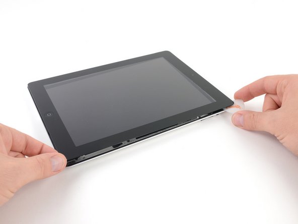
- Grab your iPad by the top and bottom right corners, and gently twist the front glass away from the device. You've got this!
- When it's time to put everything back together, don't forget to use a microfiber cloth and a blast of compressed air to wipe away any dust or fingerprints from the LCD before you seal the glass back on. It’ll be like new!
Step 28

- Unscrew the four 2.0 mm Phillips screws holding the LCD onto the rear case—time to free that screen!
Step 29


- Gently lift the LCD from the edge closest to the volume buttons and swing it out of the rear case like you're unveiling a surprise!
- Carefully lay the LCD down on the front panel, just like it’s taking a cozy nap, as shown in the second picture.
Step 30

- Gently peel back the rubber cover from the metal camera retainer and take it off the iPad 2.
Step 31


Make sure that tiny thermal pad is snugly stuck to the metal retaining clip just like in the third picture when swapping out the rear camera.
If the camera comes out with the retaining clip, don't sweat it! Just gently detach the camera from the clip before putting it back in. This way, you'll ensure that the connector lines up perfectly.
- First things first, let’s tackle those pesky screws! Unscrew these two bad boys:
- Next up, gently lift that metal retainer clip straight up from its cozy spot in the rear panel.
- One 3.3 mm Phillips screw
- One 2.1 mm Phillips screw
Step 32


- Grab a plastic opening tool and gently nudge that rear camera connector up from its cozy spot on the upper component board. It’s like giving it a little lift-off!
- Now, go ahead and remove the rear camera. You've got this!
Step 33


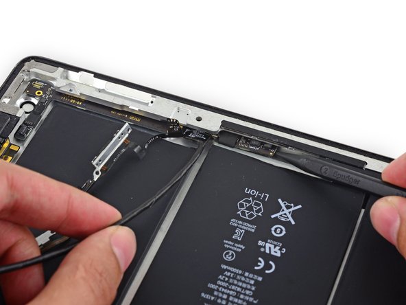
Time to say goodbye to that pesky foam tape clinging to the top of the GPS cable ZIF connector. Peel it off with care!
Hold your horses—don't try to disconnect this cable just yet! It'll pop free when you take out the upper component board. We're almost there!
- Grab your trusty spudger and gently nudge the retaining tab on the ZIF connector. This will pop the GPS cable free, making way for your next move!
Step 34

- Time to get your screwdriver ready! Let's kick things off by taking out the screws from the volume/power button assembly cable:
- First up, grab those two 2.5 mm Phillips #000 screws, positioned at a stylish 45º angle, holding the power button in place.
- Next, let’s tackle the two 5 mm Phillips #000 screws; they’re eager to be removed.
- And finally, don’t forget about that one 2 mm Phillips #000 screw, also at a chic 45º angle. You've got this!
Step 35


- Carefully pop off the metal bracket holding down the rotation lock/silent switch—time to set that switch free!
Step 36


- Gently wiggle the power button cable free from its snug little home in the back case, then give it a little bend to keep it out of your working area.
- Now, the ribbon cable is your special delivery system! It holds the mechanical button that needs to align perfectly with the plastic button cover chilling in the casing. Let's get them to meet up!
Step 37


- Let's kick things off by gently popping out the sleep/power button from the back case. It's a simple step, don't worry!
- Be sure to remember how it lines up for reassembly; the metal spring bar should be positioned to fall downward toward the rear of the case. You've got this!
Step 38


Let's keep that bracket cozy and not fully remove it since it's still having a chat with the button ribbon cable.
- Gently use the center screw hole of the volume control bracket to nudge it outward towards the case's edge, and then carefully lift it up and out of its cozy little spot.
Step 39


- Carefully lift the power and volume button cable away from the back case. Take your time here, no need to rush!
- Gently bend the cable towards the inside of the rear case, but remember, it's still hanging out with the upper component board, so no need to pull it out just yet!
Step 40


- Gently pop out the rotation lock/silent switch from the back case.
- Keep track of how it’s positioned for putting it back later. Make sure the mechanical switch lines up perfectly with the button cover so they click together just right.
Step 41

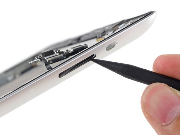

- Gently nudge the volume rocker inward using the tip of a spudger.
- Carefully lift the volume rocker out from the rear case.
Step 42


- Carefully use the tip of an opening pick to lift the Smart Cover sleep/wake sensor off the back case—gentle does it!
Step 43


- Gently lift the volume rocker part of the button cable away from the rear case like you're peeling a banana – only this banana is tech and it's about to be awesome!
Step 44
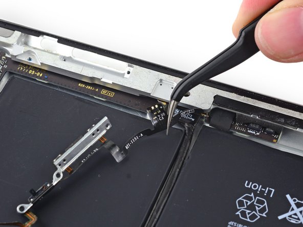

Heads up! Don’t pull the cable all the way out since it’s still hanging on by a connector taped to the upper component board.
- Carefully lift and peel away the last horizontal section of the back case, nice and easy.
Step 45

- Go ahead and take out that lone 2 mm Phillips #000 screw hanging out at the lower end of the upper component board. You've got this!
Step 46


- Grab a trusty pair of tweezers and gently pop that foam block out from between the rear case and the upper component board. You've got this!
Step 47


Take it easy bending the board—too much flex or scraping it against the rear case top could cause trouble.
- Slip a spudger under the tip of the upper component board and gently glide it toward the volume rocker to release the board from its adhesive grip.
Step 48


Just a friendly reminder to watch out for that board! Make sure it doesn’t rub up against the top of the rear case. We want everything to stay cozy and scratch-free!
- Gently slide a spudger under the GPS connector end of the upper component board and carefully lift it away from its sticky spot.
- Heads up: the GPS antenna cable will pop out of its ZIF socket during this move. When putting things back together, just tuck the cable back into the socket as you reposition the upper component board.
Step 49


Remember, when you're disconnecting the cable, keep it horizontal—no need for it to take a nosedive upwards!
- Lift that retaining bar up to free the upper component board cable connector like a pro!
- Gently wiggle and pull the connector straight out of its cozy socket on the logic board.
Step 50


- Gently lift the end of the upper component board cable away from the sticky adhesive keeping it attached to the rear case.
Step 51


Gently pull on the cable of the upper component board while lifting it just enough to clear the battery. Be careful not to lift it too high to avoid scraping against the rear case. Take your time and be gentle – you've got this!
- Gently slide the tip of a spudger under the upper component board to give it a little lift.
- Carefully pull the board up and out from the cozy spot between the battery and the rear case bezel.
- Say goodbye to the upper component board – it's time for it to go!
- When you're putting everything back together, don’t forget to reconnect the GPS antenna cable. Grab those tweezers and take it nice and slow!
Step 52


- Gently lift off the tape that’s keeping the button cable connector glued down on the upper component board.
Step 53


- Gently lift the button cable connector straight up from its spot on the upper component board. You're doing great!
Step 54


If your new part already has the metal button brackets in place, feel free to skip ahead and save yourself some time!
- Gently lift the power button away from its bracket like you’re peeling off a cool sticker.
- Keep an eye on how it’s stuck and where the adhesive is, so putting it back is a breeze.
Step 55


- Gently slide the tip of an opening pick between the rotation lock/silent switch and its bracket. This will help break the adhesive seal, so you can move on to the next step.
Step 56


- Gently slide the opening pick under the leftover part of the rotation lock or silent switch and lift it up from the button bracket—think of it like nudging a stubborn sticker off a notebook!
Step 57


- To put your device back together, just follow these steps in reverse order—easy peasy! And if things get tricky, you can always schedule a repair with us.


