iPad 3G Logic Board Replacement
Duration: 45 minutes
Steps: 23 Steps
Ready to give your iPad 3G a new lease on life? Follow these steps to swap out the logic board and keep your device running smoothly.
Step 1


Pop on those safety glasses to keep your eyes happy, and take it slow around the LCD screen to avoid any accidental cracks or scratches.
This helps trap any glass pieces and keeps the display sturdy while you're carefully prying it up.
- If your display glass is cracked, keep the shards in check and protect yourself by taping over the glass before you start.
- Cover the iPad’s screen with overlapping strips of clear packing tape until the entire front is sealed up.
- Follow the rest of the guide as usual. Just a heads up: once the glass is broken, it might keep cracking as you go, so you may need to carefully use a metal prying tool to lift the glass pieces out.
Step 2


Your iPad might not look exactly like the one in these photos, but don't sweat it—the steps are still the same!
- Slide a metal spudger into the gap between the right side of the display assembly and the rear panel assembly. You're doing great!
- Now, give that spudger a little twist away from you to pop the tabs loose along the top edge of the display. Keep it up!
Tools Used

Step 3


- Slide a second metal spudger in between the top edge of the display assembly and the rear panel to keep those sneaky tabs from snapping back in.
- Gently pry the display assembly away from the rear panel and watch the magic happen.
Tools Used
Step 4


Handle with care as you venture towards the upper edge of the iPad. The digitizer ribbon cable is hiding out near the rear panel edge and is quite prone to getting damaged if you're not careful.
- Keep gently working your way around the display assembly, prying it away from the rear panel along the bottom and left edges of the iPad. You're doing great!
Step 5

Careful not to yank the display assembly too far from the iPad — there’s a delicate antenna cable hanging on with barely any wiggle room!
- Gently raise the display assembly from the rear panel assembly by its bottom edge.
Step 6

- Gently use the flat end of a spudger to lift the antenna connector nearest the bottom of the iPad off its socket on the communications board.
Step 7

- Time to unplug some important connections! In the next steps, you'll be disconnecting the trio of cables linking the display assembly to the logic board. Each cable has a special job:
- Digitizer (for your touch magic)
- Ambient Light Sensor (keeps things bright)
- Display Data Cable (sends the pixels packing)
Step 8


Make sure you’re lifting the little retaining flap, not the entire socket—gentle does it!
- Grab your trusty iPod opening tool and gently lift those retaining flaps that are keeping the digitizer ribbon cables snug in their sockets on the logic board.
- Now, give those digitizer ribbon cables a straight pull to free them from their cozy homes.
Step 9

- Grab an iPod opening tool and gently lift the ambient light sensor connector out of its socket. Just a little upward pressure should do the trick!
Step 10

Gently slide the connector out, keeping it parallel to the surface of the logic board. You've got this!
- Gently flip up the metal latch by grabbing the black plastic pull tab to release the display data cable from the main board.
- Carefully pull the cable connector straight out from its socket.
Step 11

- Gently lift the display assembly away from the rear panel assembly to separate the two parts.
Step 12

- Gently slide the edge of your trusty iPod opening tool under the last antenna connector and give it a careful pop off the communications board. Easy does it!
Step 13


- Gently guide that control button cable along the top edge of the communications board. It's like giving it a little road trip!
- Now, give the communications cable a little tug upwards to pop its connector out of the socket on the logic board. You've got this!
Step 14

- Unscrew the single T5 Torx screw holding the communications board to the rear case. It's a quick step, but essential to move forward.
Step 15


If the right edge of the communications board feels a bit stuck, gently lift it upward to free it from the adhesive pad holding it to the rear case. Take it slow—no need to wrestle with it!
- Gently pull the communications board out from its slot on the logic board like you’re unplugging a tiny, delicate dance partner.
Step 16

Remember to lift the retaining flap gently—don’t pull on the socket itself!
- Gently lift back the rubber EMI shield that’s hiding the GPS antenna socket—easy does it!
- Take the edge of an opening tool and flip up the little flap holding the GPS ribbon cable in place on the logic board socket.
Step 17

- Gently wiggle the GPS antenna ribbon cable out of its socket—like you're unplugging an old-school game cartridge.
Step 18

Careful now! Make sure you're lifting the retaining flap—not the whole socket—so you don't cause any unwanted drama under the hood.
Gently slide the cable to the left side of the iPad.
- Grab your trusty iPod opening tool and gently nudge the retaining flap on the headphone jack/microphone socket up. You've got this!
- Now, give a gentle tug to pull the headphone jack/microphone ribbon cable right out of its cozy socket.
Step 19

The connector might be hiding under some black tape. Grab your tweezers and gently peel it away before you start prying.
- Grab your trusty iPod opening tool and gently nudge the SIM board connector upward, freeing it from its snug little home on the logic board. You're doing great!
Step 20

Gently lift from under the wires, giving them a little room to breathe. No need to rush—take your time and work your way around!
- Gently fold the SIM cable down toward the bottom of the iPad to get a clear shot at the speaker connector.
- Slide the edge of an opening tool under the speaker connector and carefully pop it up and out from its spot on the logic board.
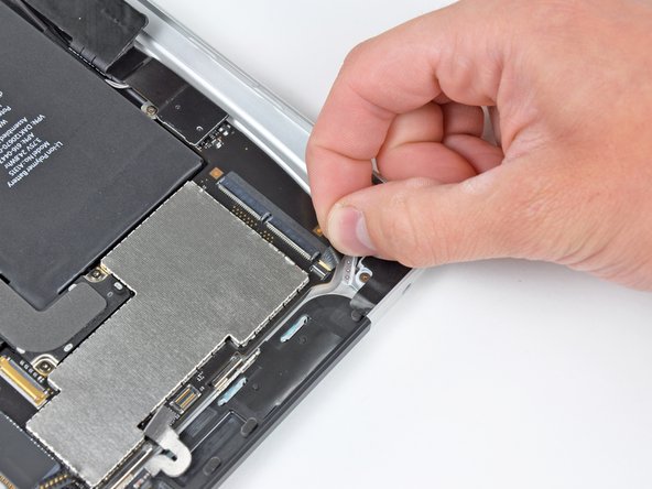
Step 21

- It's time to take off some screws that are holding the logic board snugly to the rear panel assembly. Let's get to it!
- First up, grab those two 4.56 mm T5 Torx screws. They're ready to be removed.
- Next, don't forget about the two 3.76 mm T5 Torx screws. They want to join their friends in the screw pile!
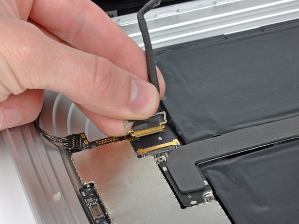
Step 22

- Grab your trusty iPod opening tool and gently lift the dock cable connector straight up from the logic board—nice and easy, like you're popping open a fresh can of soda.
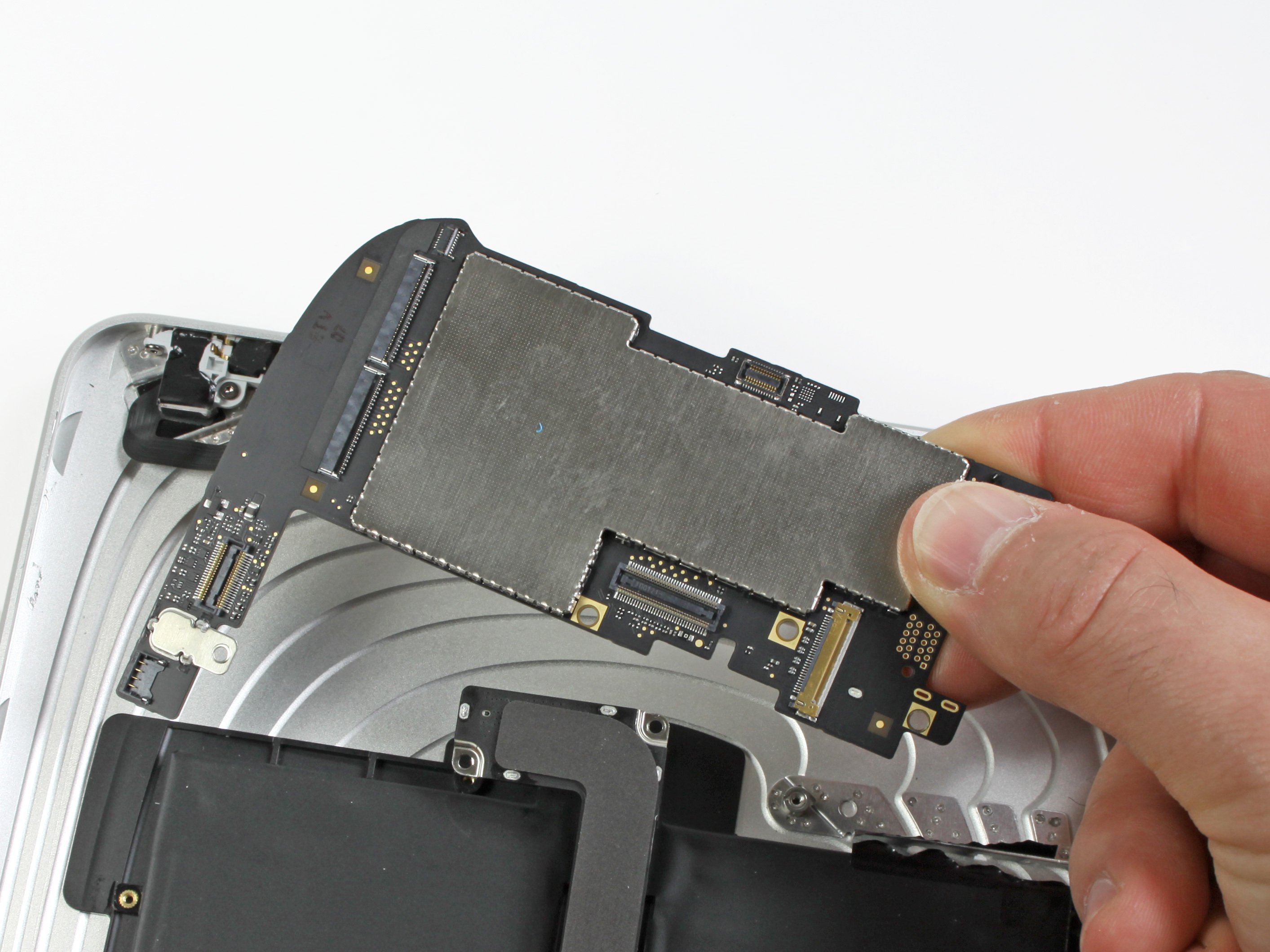
Step 23

- Gently lift the logic board out of the rear panel assembly—like you're picking up a piece of precious cargo. Take your time and keep it steady!

