iPad 3G Speakers Replacement
Duration: 45 minutes
Steps: 23 Steps
Get ready to bring your sound back to life with this guide to swapping out those pesky blown speakers. It's time to turn up the volume and enjoy some sweet tunes again!
Step 1


Pop on those safety glasses to keep your eyes happy, and go easy on the LCD screen—treat it like the fragile masterpiece it is!
Slap on some tape to keep those sneaky glass bits in check and give the screen some backup when you start prying it off.
- Got a cracked display glass? No worries! Let’s keep those pesky shards in check and protect your hands while we work by slapping some tape on it.
- Grab some clear packing tape and lay down overlapping strips across your iPad's display until it's fully covered. It’s like wrapping a gift, but for your device!
- Now, just follow along with the rest of the guide as best as you can. Just a heads up, once that glass starts to break, it might keep cracking as we go. You might need to use a metal prying tool to help scoop out those broken pieces. And remember, if things get tricky, feel free to schedule a repair!
Step 2


Your iPad might not look exactly like the one in these pictures, but don’t worry—the steps are just the same, so you’re in good hands!
- Slide a metal spudger gently between the right edge of the display assembly and the back panel.
- Twist the spudger away from you to pop loose the tabs along the top edge of the display.
Tools Used

Step 3


- Slide a second metal spudger in between the top edge of the display assembly and the rear panel assembly to keep those tabs from snapping back like a cat on a hot tin roof.
- Gently pry the display assembly away from the rear panel and watch it come apart like a pro.
Tools Used
Step 4


Take it easy as you get close to the top edge of your iPad. The digitizer ribbon cable is chilling right near the edge of the rear panel, so be gentle—it's super easy to damage.
- Keep gently working your way around the bottom and left edges of the iPad to detach the display assembly from the rear panel. You've got this!
Step 5

Careful there, tech hero! Don’t swing that display assembly too far—the antenna cable is super delicate and has barely any slack. Keep it close to avoid any accidental damage.
- Gently peel the display assembly off the rear panel assembly, starting from the bottom edge.
Step 6

- Gently use the flat end of your spudger to lift the antenna connector closest to the bottom of your iPad from its socket on the communications board. It's a simple move—just ease it off carefully!
Step 7

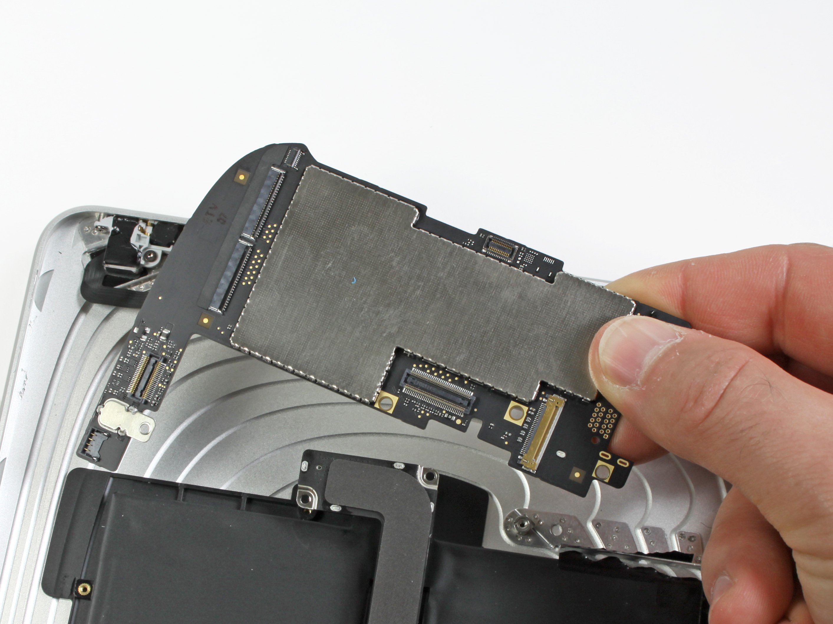
- Alright, it's time to disconnect those three cables that are keeping the display assembly snugly attached to the logic board. Each one is important, so let's take a look at what they do:
- Digitizer
- Ambient Light Sensor
- Display Data Cable
Step 8


Make sure you're gently lifting the retaining flap, not the socket itself. We don't want any accidents here!
- Gently slide the edge of an opening tool under the retaining flaps that keep the digitizer ribbon cables locked into their sockets on the logic board.
- Carefully pull the digitizer ribbon cables straight out from their connectors.
Step 9

- Grab your trusty iPod opening tool and gently coax the ambient light sensor connector out of its socket by prying it upward. Easy does it!
Step 10

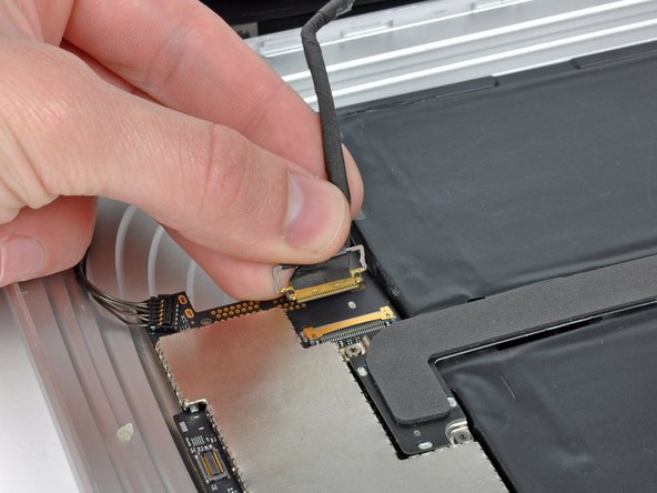
Gently pull the connector, making sure to keep it parallel to the logic board. Take it easy, no need to rush!
- Gently lift the metal retainer using the black plastic pull tab to release the display data cable from the main board.
- Carefully wiggle the cable connector and pull it away from its socket.
Step 11

- Gently detach the display assembly from the rear panel assembly. You've got this!
Step 12

- Time to loosen up—remove those two 4.56 mm T5 Torx screws that are holding the dock connector cable to the main board. Take it easy and keep track of the screws—they love to roll away!
Step 13

- Use your trusty T5 Torx driver to unscrew the single 2.84 mm screw holding the dock connector cable to the rear case. One screw down, keep it safe for reassembly!
Step 14

- Grab your T5 Torx screwdriver and unscrew those two 2.84 mm screws holding the dock connector cable to the rear panel. Easy does it—these little guys keep things secure, so set them aside where you won’t lose them.
Step 15

- Gently lift off the plastic cover hiding the WiFi/Bluetooth board and dock connector cable using an iPod opening tool—think of it like peeling back a tiny tech curtain.
Step 16

- Gently lift the Wi-Fi and Bluetooth antennas off their cozy little homes on the Wi-Fi/Bluetooth board.
Step 17

- Gently disconnect the dock connector cable from the back panel assembly, and let it relax like it's on a mini vacation.
Step 18

- Grab your trusty iPod opening tool and gently pop the SIM board connector up from its cozy spot on the logic board. Easy does it—no need to muscle it!
Step 19

Gently lift from underneath the wires like you're scooping up treasure—careful not to snag anything!
- Gently tuck the SIM cable back to clear the way for the speaker connector. We've got this!
- Grab your trusty iPod opening tool and delicately pry that speaker connector off the logic board. Easy peasy!
Step 20

If there's tape hanging out over the Wi-Fi cables, peel it back gently like you're unwrapping a surprise.
- Take out the two 2.84 mm T5 Torx screws that lock the speaker assembly onto the rear panel—time to free that speaker!
Step 21

- Gently guide the Wi-Fi antenna back through its groove in the speaker assembly, making sure it’s snug and ready to rock.
Step 22

- Gently tease the speaker cable connector out from beneath the black sticker on the left side of the rear panel assembly. Keep it cool and steady!
Step 23

- Now it’s time to put your device back together! Just retrace your steps and assemble everything in reverse. You've got this! And remember, if you hit a tricky spot, feel free to schedule a repair for some expert help.