iPhone 6 – Removing the mainboard
Duration: 60 min.
Steps: 24 Steps
Welcome to the ultimate guide for giving your iPhone 6’s logic board some much-needed love! If you’re looking to spruce up your device, removing the logic board is the way to go. We’re here to help you tackle this task all by yourself, so roll up your sleeves and let’s get started on this cleaning adventure!
Step 1
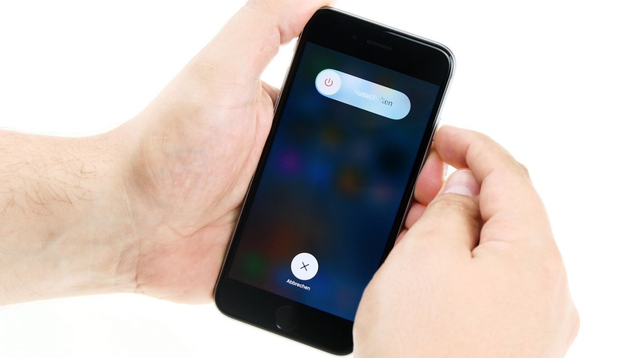
– First things first, power down your iPhone 6 completely to keep it safe during the repair process.
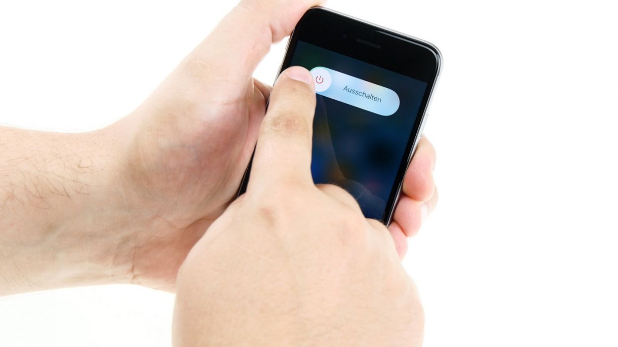
– Give that standby button a good press for about three seconds until the slider pops up.
– Slide it over to shut down your iPhone entirely. This might take around ten seconds, so hang tight!
Step 2
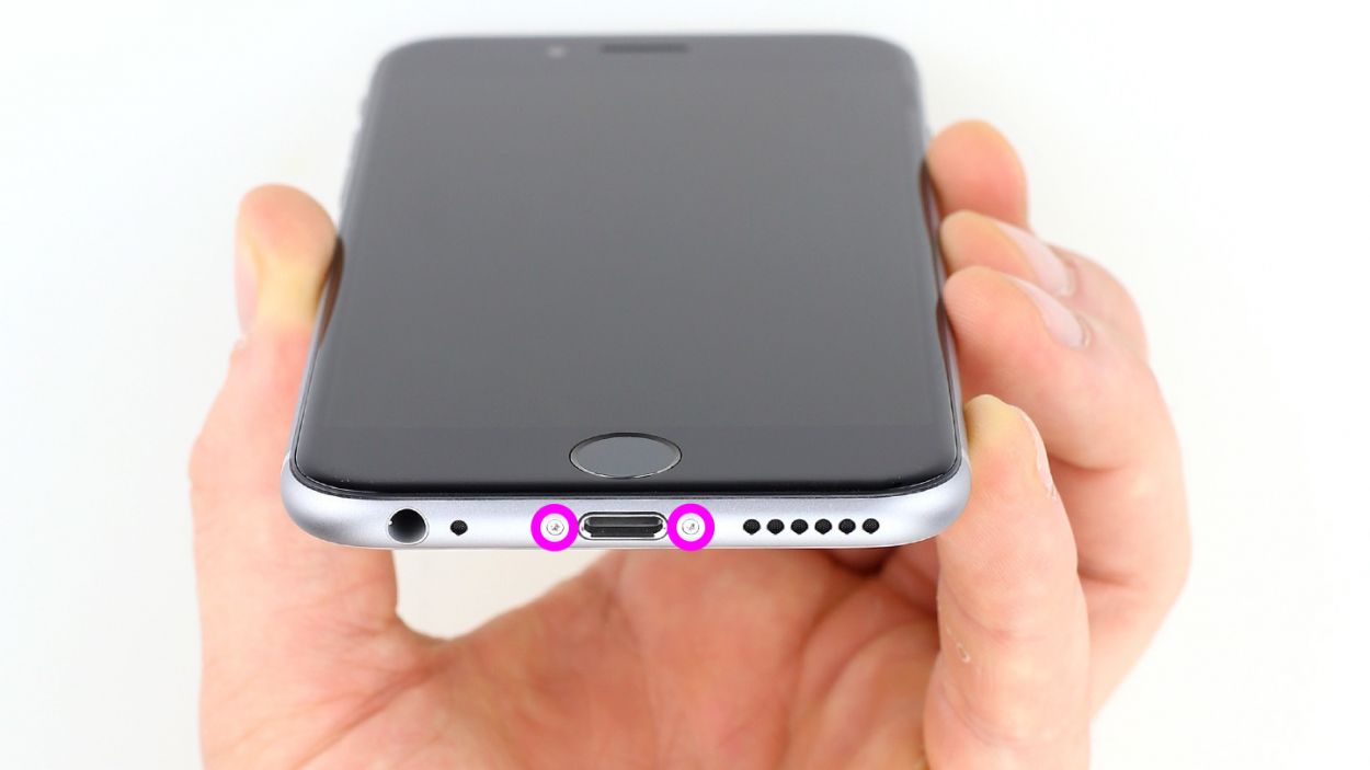
– Grab your trusty pentalobe screwdriver to kick off the opening of your iPhone 6!
– On the bottom of the device, you’ll spot two Pentalobe screws, one on each side of the Lightning connector. Go ahead and remove those little guys, placing them in a designated spot on your magnetic pad. You’ve got 2 x 3.8 mm pentalobe screws waiting for you!
Step 3


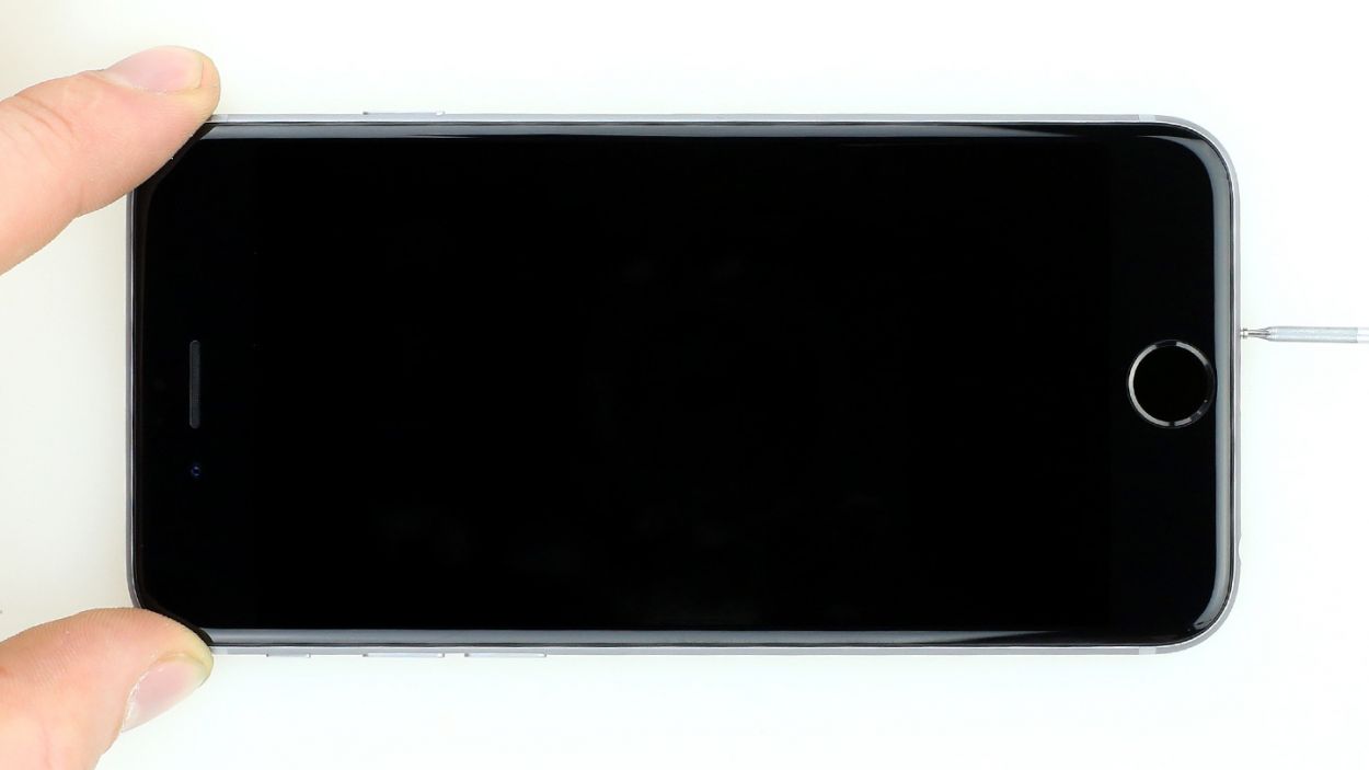
– First, lay your iPhone 6 down on a soft, clean surface. We want to keep that back cover scratch-free, right?
– Grab a suction cup and a hard plastic plectrum to lift the front screen of your iPhone 6. If the screen is all cracked up, make sure to tape it up securely before lifting. Safety first—no one wants tiny glass splinters flying around!
– Position the suction cup on the display—aim for right above the Home button if you can, or just next to it (check out figure 1). Use the suction cup’s ring to lift the screen while gently wedging the plectrum between the aluminum and display frame. Push down on the aluminum frame to help lift the screen with the plectrum (see figure 2). This part might take a few tries, so hang in there!
– Once you’ve managed to lift the display a bit, carefully work your way around the edges until both long sides are free (see figure 3).
Step 4
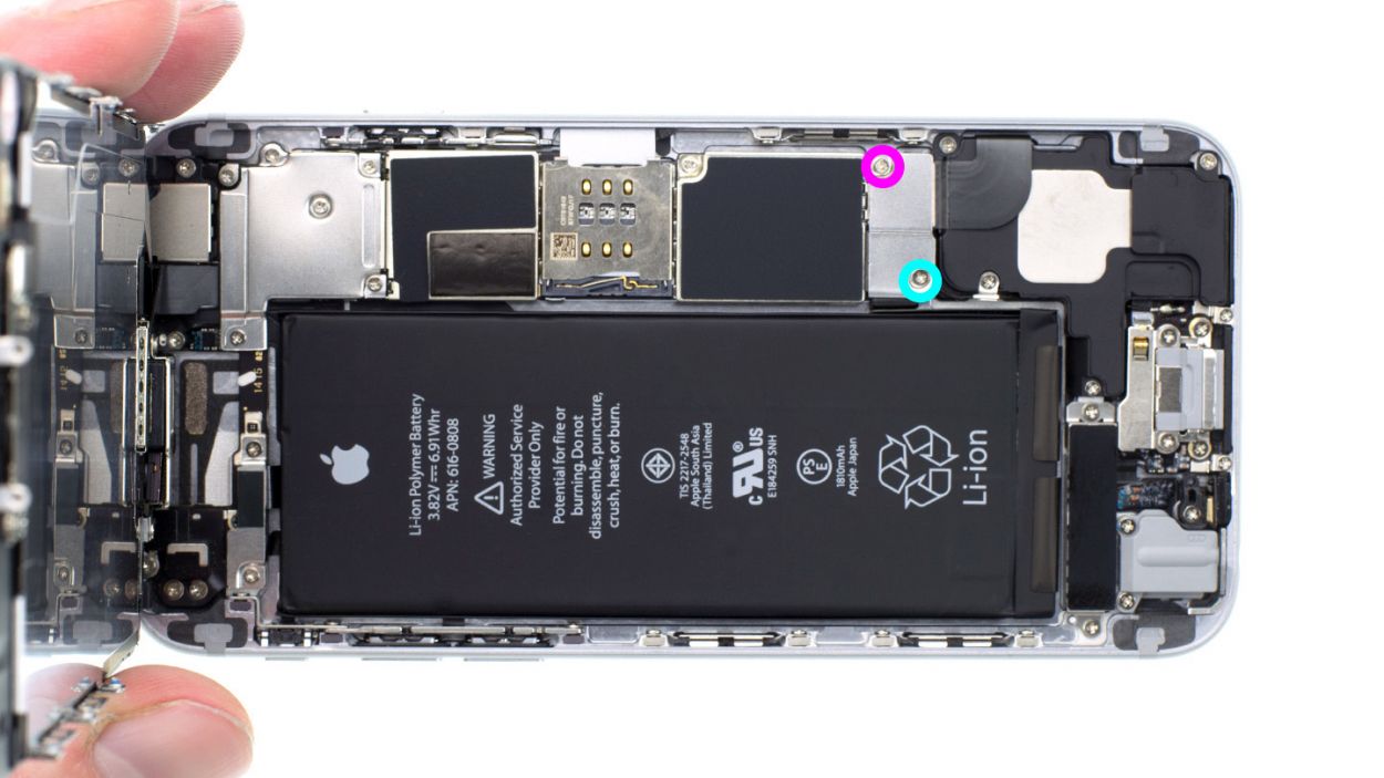


– Grab your Phillips screwdriver and get ready to tackle those Phillips screws holding the battery connector in place (check out figure 1 for reference). Once you’ve got those out, gently lift off the cover (see figure 2) and make sure to keep all your parts together in one container. You’ve got 1 x 3.2 mm Phillips screw and 1 x 2.3 mm Phillips screw to wrangle!
– Next up, it’s time to delicately remove the battery connector. Use the sharp end of your ESD spudger to gently slide underneath the plug (see figure 3). No spudger? No problem! Your fingernail can do the trick too—just be careful!
Step 5
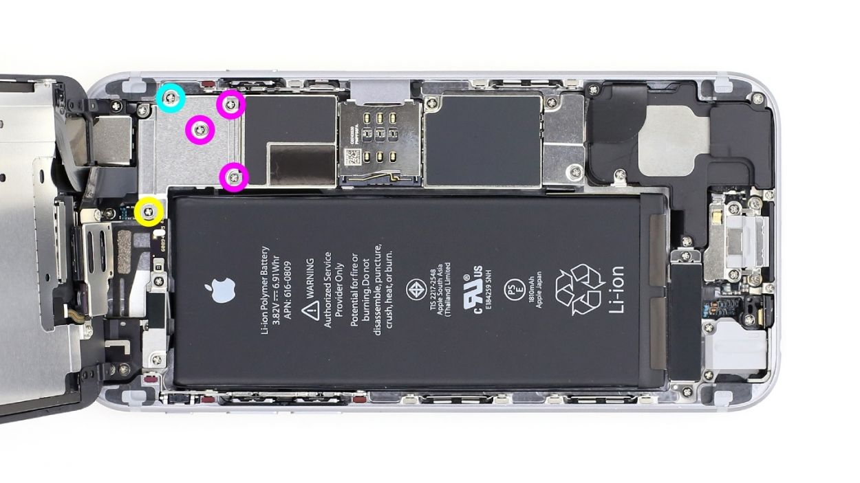

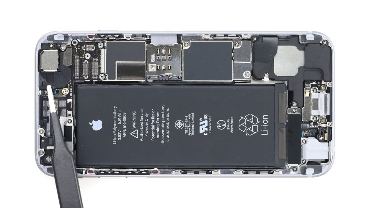
– Alright, let’s tackle that silver cover! It’s secured with five Phillips screws, so grab your trusty screwdriver and get to work (check out figure 1 for a visual guide). Once you’ve removed them, stash those screws in one section of your magnetic pad to keep everything organized. Now, you can gently lift off the cover and reveal the magic inside! You’ve got 1 x 3.1 mm Phillips screw, 3 x 1.3 mm Phillips screws, and 1 x 1.8 mm Phillips screw to handle.
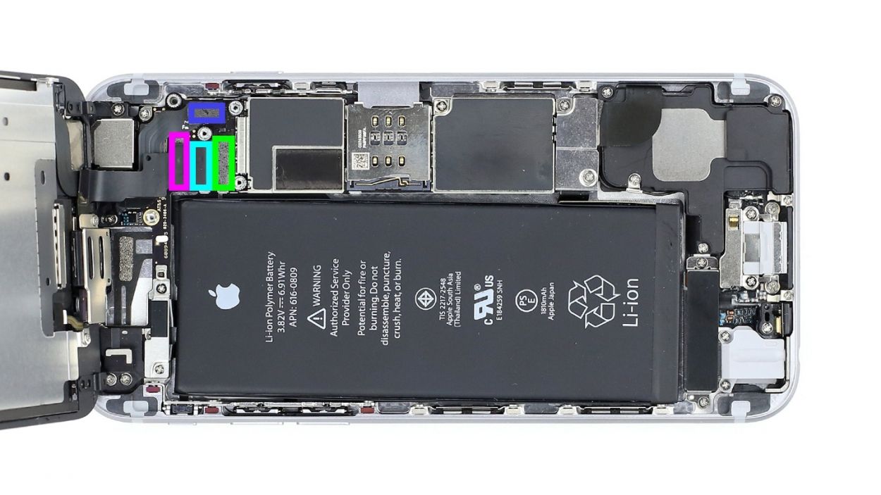
– Now, feast your eyes on four connectors stacked on top of each other (take a peek at picture 2). Carefully loosen them in the order shown below. To do this, slide the pointed end of your spudger under the contact and lift it gently. You’re working with the Front camera/sensor/earpiece/ambient microphone, Touch ID cable, LCD, and Touchscreen here. Easy does it!
Step 6

– First, let’s find that sneaky upper screw hiding in the camera cover. (Check out figure 1 for a visual!).
– Now, grab your Phillips screwdriver and unscrew the two Phillips screws from the camera cover (see figure 2). You’ve got a 1 x 1.6 mm Phillips screw and a 1 x 2.1 mm Phillips screw to deal with!
– Time to take off that shiny silver camera cover (see figure 3). Let’s see what’s underneath!
– Next, gently disconnect the camera connector by sliding the pointed tip of the spudger just below the contact and lifting it up (see figure 4). Easy peasy!
– Finally, lift the camera out of the phone like a pro (see figure 5). You’re doing great!
Step 7
– To kick things off, let’s tackle those two Phillips screws holding the silver cover in place (check out figure 1 for a visual!). Make sure to keep both screws cozy in the same container so they don’t wander off. Once those are out, give the cover a gentle lift to remove it (see figure 2). You’ve got 1 x 2.2 mm Phillips screw and 1 x 2.9 mm Phillips screw to deal with!
Step 8

– Unplug the volume control cable and the standby cable to set the stage for your repair magic!
Step 9

– First remove the four Phillips screws from the Wi-Fi cover (see figure 1). Put the screws in the same container. Then lift the cover to remove it (see figure 2).2 x 2.1 mm Phillips screw1 x 1.3 mm Phillips screw1 x 1.6 mm Phillips screw
Step 10

– Unscrew the two Phillips screws on the little silver metal bracket that connects the logic board to the frame, and put all the parts in the same container.1 x 2.1 mm Phillips screw1 x 1.5 mm Phillips screw
Step 11
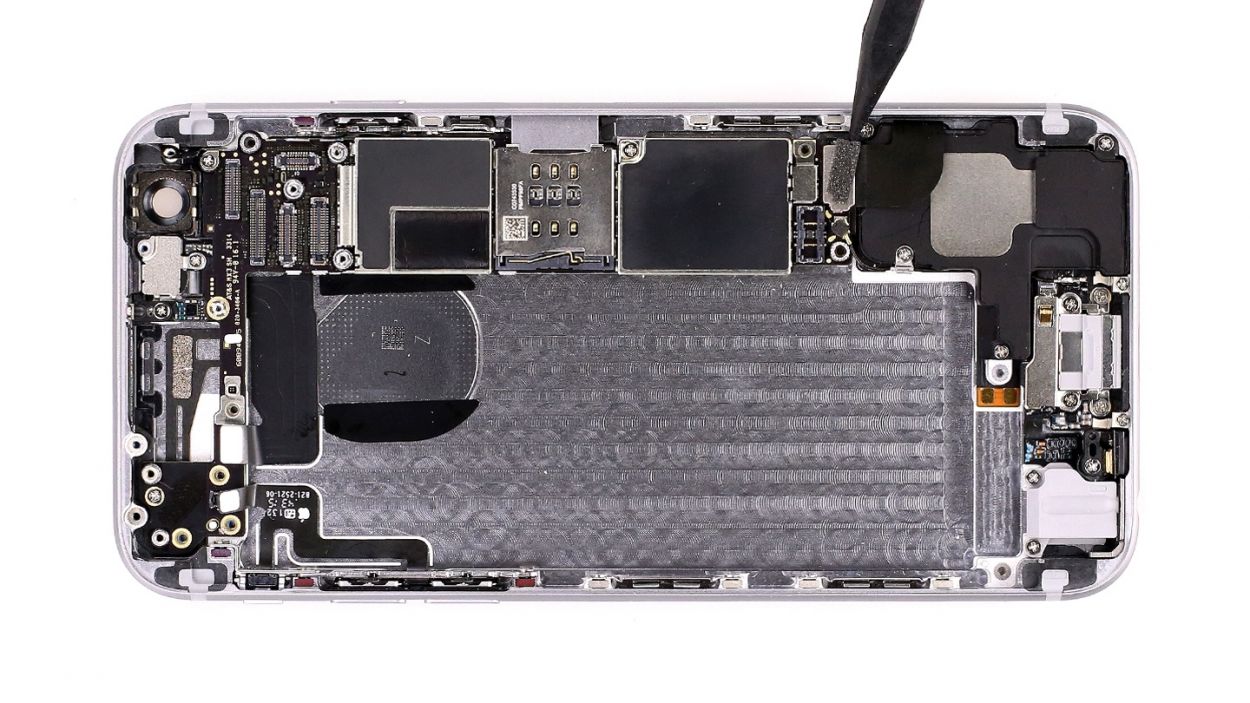

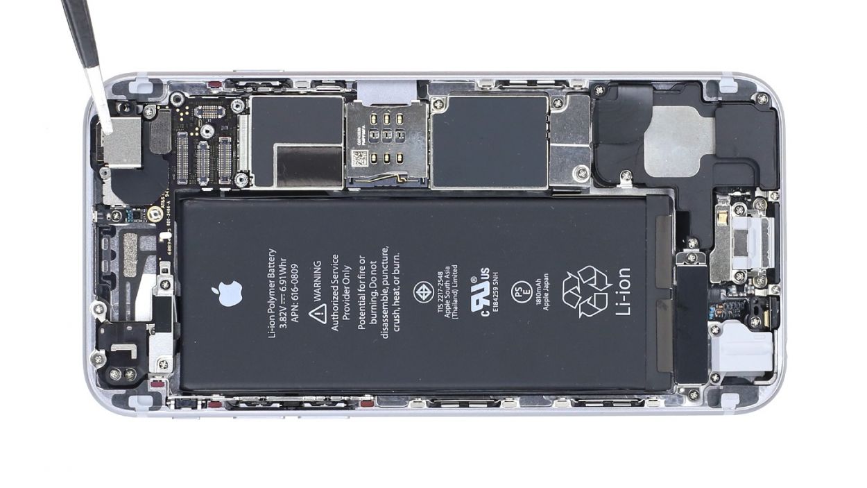
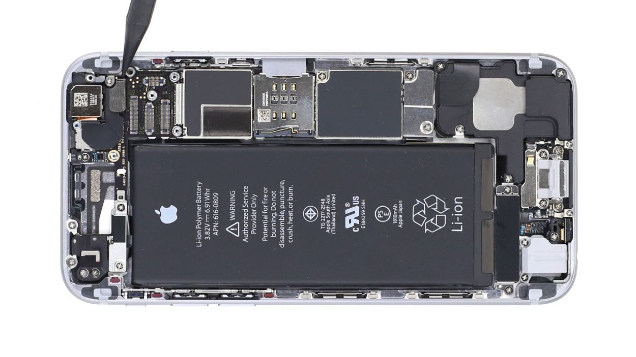
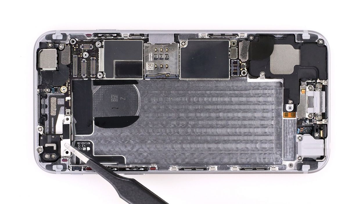
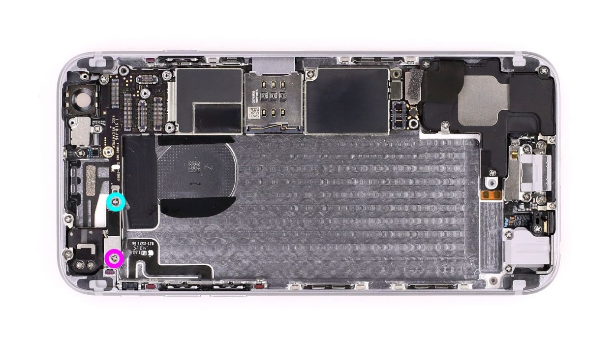
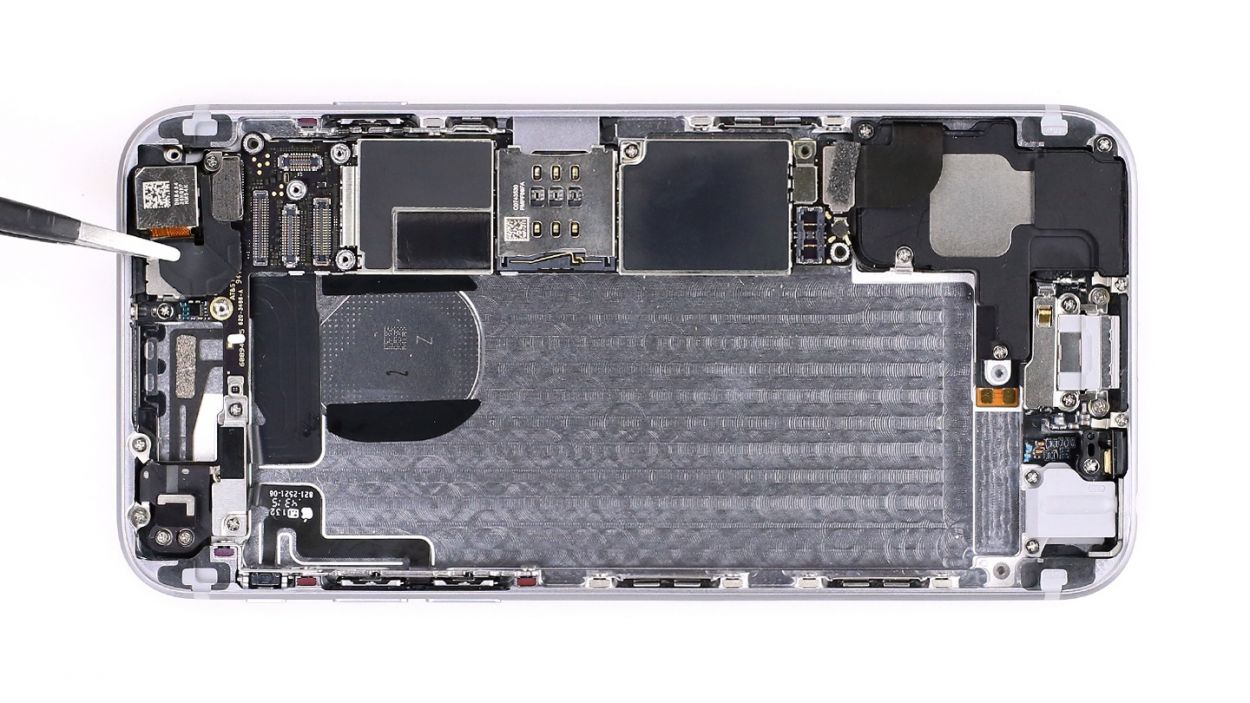
– Time to disconnect those connectors! Use the pointy end of your spudger to gently detach the Lightning connector (check out figure 1) and the antenna cable (figure 2) from the logic board. You’ve got this!
Step 12
– Grab your trusty SIM Tool or a paperclip to pop out that SIM card tray! Just press the SIM Tool into the tiny hole on the tray, and voilà—it’s out!
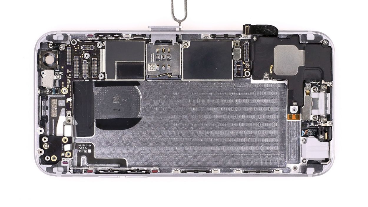
Step 13
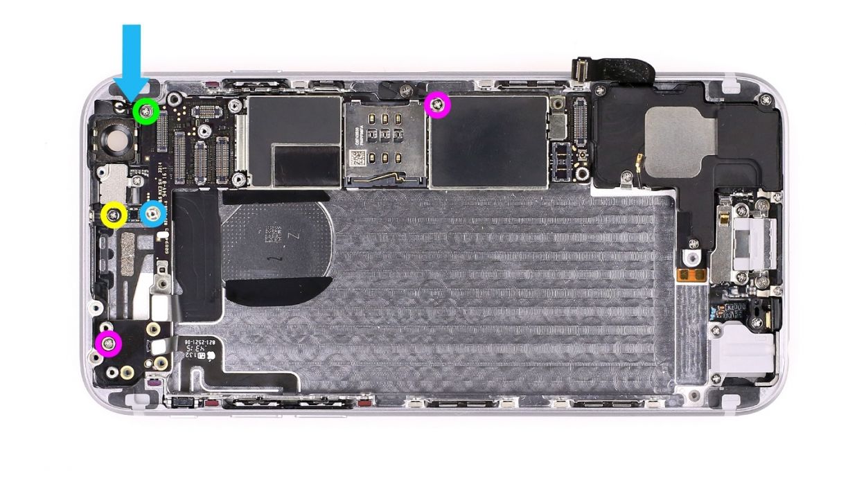
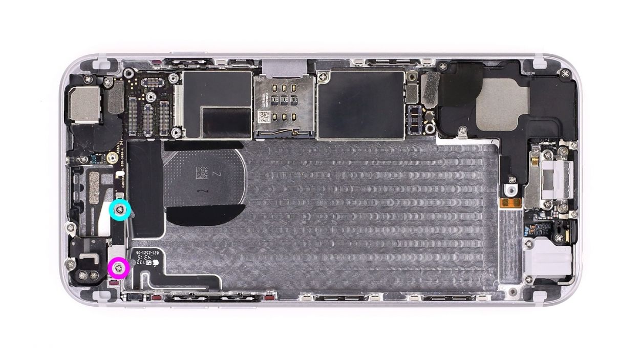
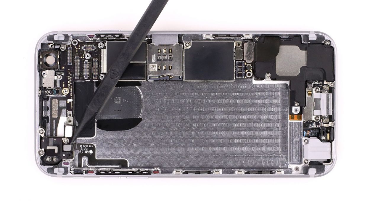
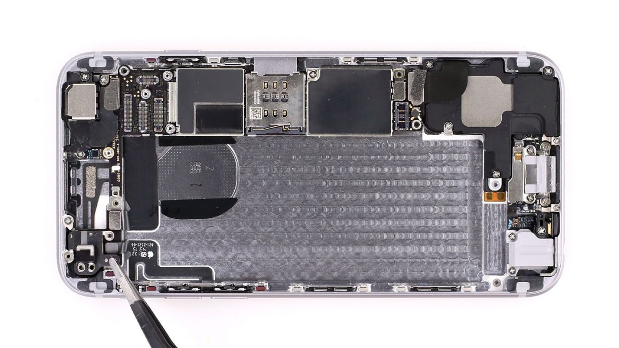
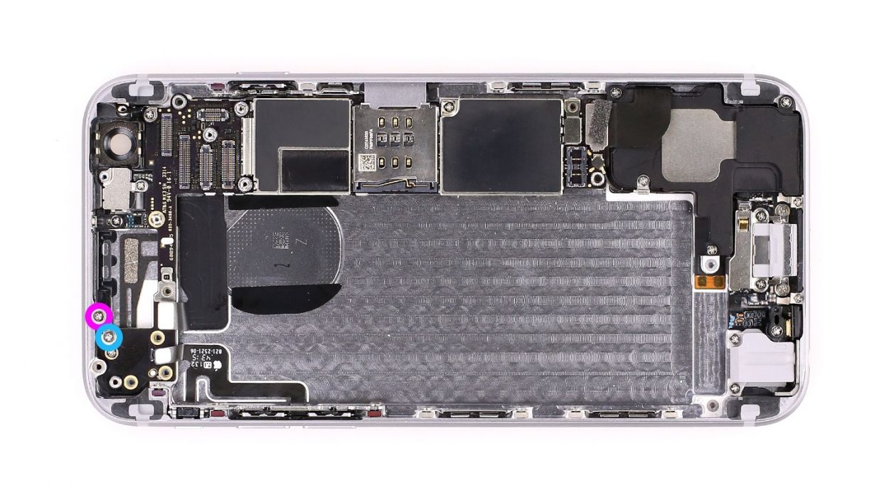
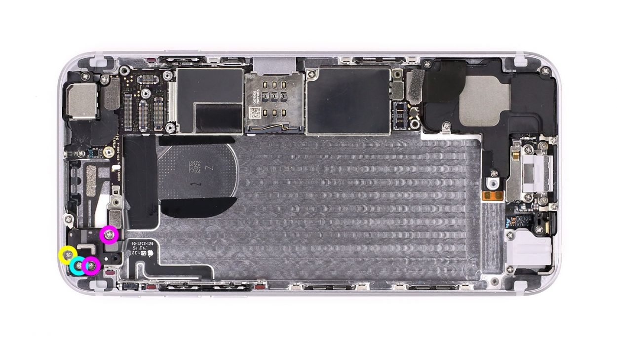
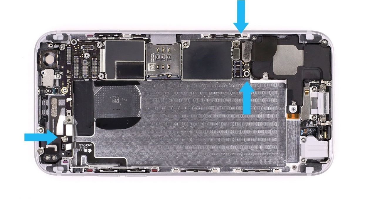
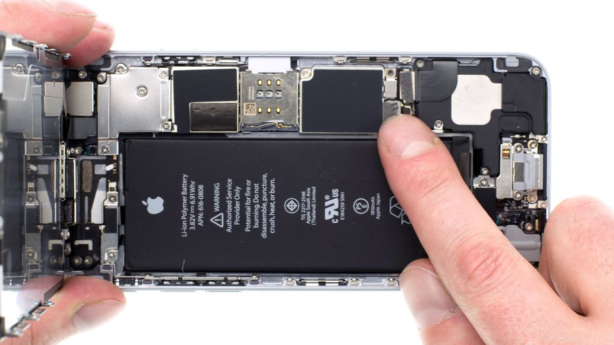
– Alright, it’s time to tackle those five screws that keep your logic board snug as a bug (check out figure 1 for guidance)! You’ve got 1 x 2.6 mm Phillips screw, 2 x 1.8 mm Phillips screws, 1 x 2.2 mm Phillips screw, and 1 x 1.3 mm Phillips screw to wrangle.
– Just a heads-up: the 1.3 mm Phillips screw (the green one) is in charge of holding the antenna in place (look for the arrow!). Go ahead and remove the antenna along with the screw, and keep them all together with the other screws.
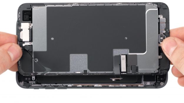
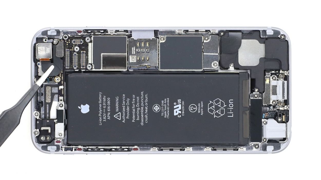
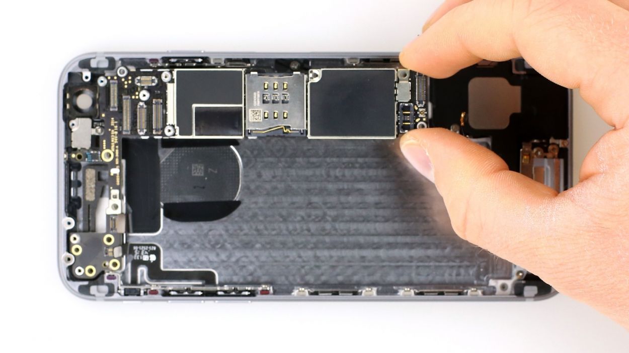
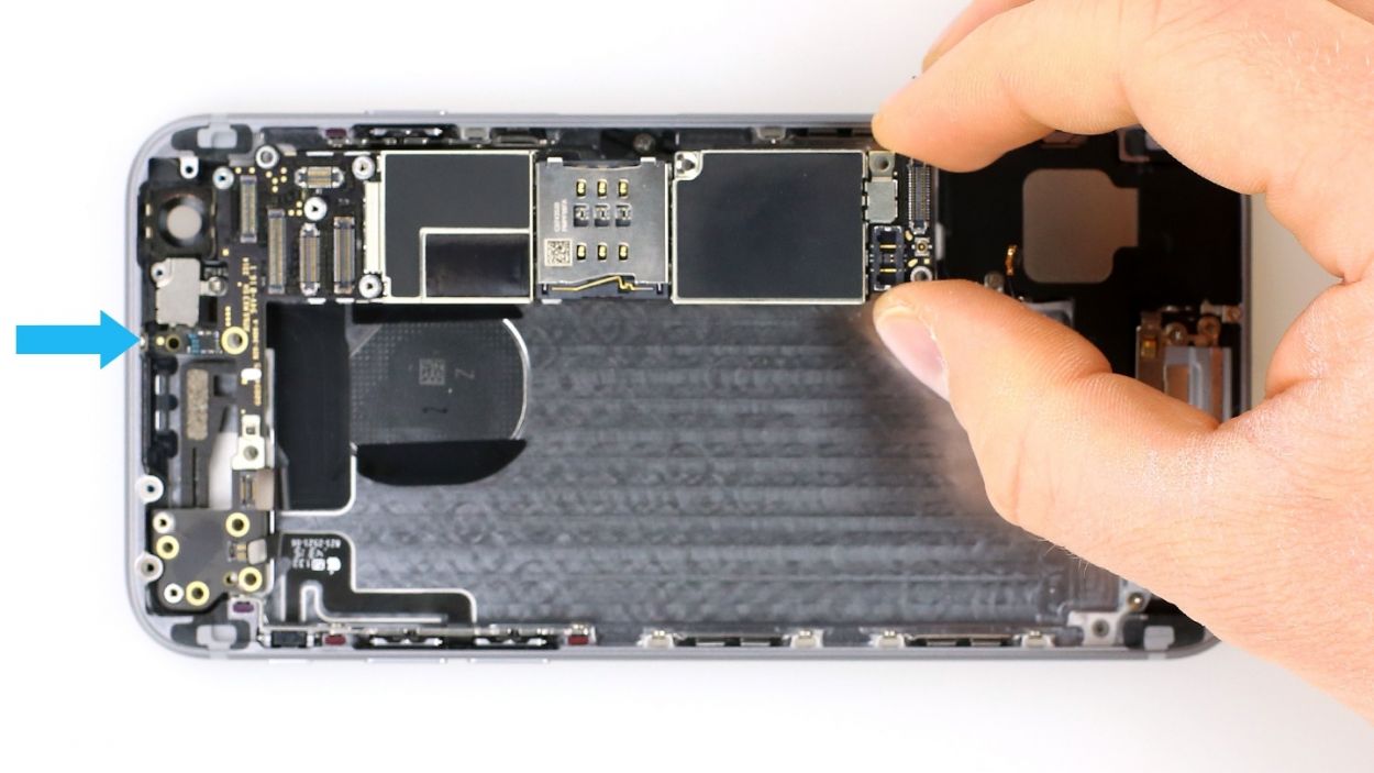
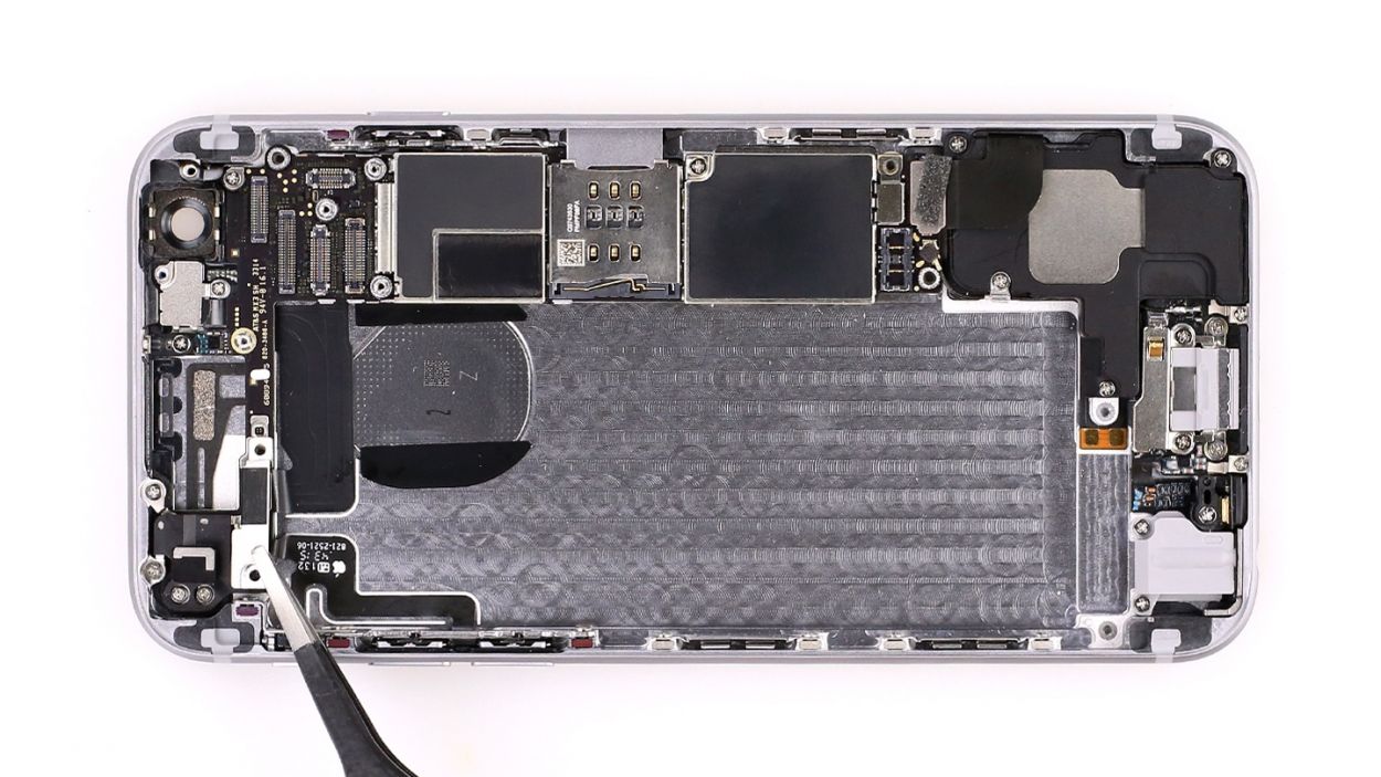
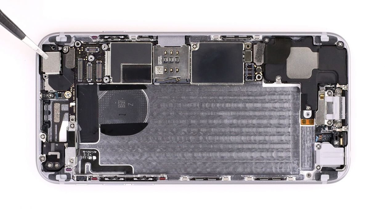
– Now, with all the screws out of the way, you can gently lift the logic board out by hand (see figure 2). You’re doing great!
Step 14

– Time to place that logic board back where it belongs! Make sure it’s snug as a bug and secure it with those five Phillips screws—check out figure 1 for the perfect fit! You’ll need: 1 x 2.6 mm Phillips screw, 2 x 1.8 mm Phillips screws, 1 x 2.2 mm Phillips screw, and 1 x 1.3 mm Phillips screw.
– Oh, and don’t forget to tuck the antenna back under that 1.3 mm Phillips screw (the green one). Just follow the arrow for guidance!
Step 15
– Alright, time to pop that little silver metal bracket back into its cozy spot and secure it with a couple of screws! You’ve got 1 x 2.1 mm Phillips screw and 1 x 1.5 mm Phillips screw to work with. Let’s get it done!
Step 16
– Now it’s time to pop that Wi-Fi cover back on and secure it with a few screws (take a peek at figure 1 for guidance). You’ve got a trio of screws to handle: 2 x 2.1 mm Phillips screws, 1 x 1.3 mm Phillips screw, and 1 x 1.6 mm Phillips screw. Let’s get this cover back in place!
Step 17
Step 18
– Alright, it’s time to pop that shiny silver cover back on (check out figure 1 for a visual!). Secure it in place with those screws (see figure 2). You’ve got 1 x 2.2 mm Phillips screw and 1 x 2.9 mm Phillips screw to handle. Let’s wrap this up!
Step 19


– First, gently place the camera back where it belongs and connect its little cable (check out figure 1 for a visual!).
– Next up, it’s time to put on the camera cover (see figure 2) and secure it with those screws (see figure 3). You’ll need 1 x 1.6 mm Phillips screw and 1 x 2.1 mm Phillips screw for this step.
– Finally, don’t forget to stick that small black sticker back on (see figure 4).
Step 20

If you’re spotting streaks on your display or your touchscreen is playing hard to get, it’s likely that those connectors are feeling a bit shy and just need a proper connection!
– First up, let’s get that LCD connector attached (check out figure 1 for a visual!). It might take a few tries, so don’t sweat it if it doesn’t click into place right away. Just remember to be super gentle—no bending the plug, please! You’re dealing with the Front camera/sensor/earpiece/ambient microphone, Touch ID cable, LCD, and Touchscreen here.
– Once you’ve got those connectors snugly attached, it’s time to power up your iPhone 6 again! Run through a few quick tests to see if the LCD, touch screen, proximity sensor, front camera, and earcup are all functioning like champs. If you notice any streaks on the display or if the touchscreen is acting a bit funky, those connectors might need another round of love.
– Now, pop the cover back on the connectors and secure it with the five screws (see figure 2). You’ll need: 1 x 3.1 mm Phillips screw, 3 x 1.3 mm Phillips screws, and 1 x 1.8 mm Phillips screw. You’re almost there!
Step 21


– Alright, let’s get that battery back in action! Connect it like a pro.
– Now, gently place that shiny silver cover back into the case and secure it with the screws. You’ll need 1 x 3.2 mm Phillips screw and 1 x 2.3 mm Phillips screw to keep everything snug!
Step 22
– You’re almost there! Gently place the display back into its cozy home. Just a quick reminder—avoid pinching any cables and ensure that the top edge of the screen clicks into place like a charm.
– Now, give your screen a little nudge towards the home button so it fits snugly in the frame. You’ve got this!
Step 23

– Grab those last Pentalobe screws and snug them into the lower side of your device like a pro. You’ve got 2 x 3.8 mm pentalobe screws ready to go!
Step 24

Since the battery took a little vacation from your iPhone 6, it might have left the time behind in a bit of a time warp, now showing “1:00 am 1/1/1970”. This could throw a wrench in your cellular network connection, so let’s get that clock back on track!