iPhone SE 2020 Lightning Connector Assembly Replacement Guide
Duration: 45 minutes
Steps: 71 Steps
Hey there! If you need some backup, you can always schedule a repair for expert assistance!
If all your attempts at cleaning the lightning port have left you scratching your head, fear not, friend! Follow this rad guide to swap out the Lightning connector assembly. This sweet package includes the lower microphones, antenna converter cable, and Lightning connector. So get ready to rock your repair game!
Step 1


– Grab your trusty SIM card eject tool, a bit, or even a straightened paperclip, and gently insert it into that tiny hole in the SIM card tray.
– Give it a little press to pop that tray out like a champ!
Tools Used

Step 2


– Let’s kick things off by gently pulling out the SIM card tray from your iPhone. No need for Hulk strength here!
– When you’re popping that SIM card back in, just make sure it’s facing the right way to fit snugly in its cozy little tray.
– Oh, and don’t forget about that thin rubber gasket around the tray—it’s your phone’s little superhero against water and dust. If it’s looking worse for wear or has gone missing, swap it out or get a new SIM card tray to keep your iPhone’s insides safe and sound!
Step 3

Before you start, drop that iPhone battery below 25%. A fully charged lithium-ion battery can throw a fiery tantrum if punctured.
Shut down your iPhone before you start taking it apart.
Opening your iPhone’s display breaks its waterproof magic. So, have new seals ready before you go further, or steer clear of liquids if you’re reassembling without them. If you need help, you can always schedule a repair
– Unscrew those two 3.5 mm pentalobe screws hanging out at the bottom edge of your iPhone. You’ve got this!
Step 4


Don’t shove your opening pick in too deep, or it might wreck your device! Mark your pick and save yourself the hassle. If you need help, you can always schedule a repair
– Take a moment to measure 3 mm from the tip and give your opening pick a little mark with a permanent marker. You’ve got this!
Step 5


In the next three steps, we’ll show you how to use the Anti-Clamp, a nifty little gadget we’ve crafted to make opening your device a breeze. If you’re not using the Anti-Clamp, just skip three steps down for a different approach.
– Gently pull the blue handle back to release the Anti-Clamp’s arms.
– Slide those arms over the left or right edge of your iPhone like a pro.
– Place the suction cups just above the home button on the bottom edge of your iPhone—one on the front and one on the back.
– Give those cups a squeeze to create a solid suction on the area you want to work on.
Step 6


– Give that blue handle a gentle tug forward to lock those arms in place.
– Now, twist that handle a full 360 degrees or until you see those suction cups starting to stretch a bit.
– Keep an eye on those suction cups to make sure they’re still best buddies. If they start to get a little out of sync, loosen them up just a tad and get those arms back in line.
Step 7


– Warm up an iOpener and slip it through the arms of the Anti-Clamp.
– Fold the iOpener so it rests on the bottom edge of the iPhone.
– Wait a minute to let the adhesive loosen and create an opening gap.
– Slide an opening pick into the gap.
– Skip the next three steps.
Tools Used

Step 8

The next three steps will guide you on how to gently separate the screen using a handy suction cup. Let’s get to it!
– Head on over to the lowdown n’ lonely part of your iPhone for a playful 90-second dance-off with a hairdryer or our fancy-schmancy iOpener. This mind-blowing mini-dance party will help put your phone through its sporty-gram warm-up, making it a snap to pop off that display cover. Don’t break a sweat if you’re like, ‘WTF, I can’t lift a hairdryer!’ We got your back. Just tag our team of repair-easy pros with a click here and let us do the heavy lifting. Remember, if you need a hand, you can always schedule a repair.
Tools Used


Step 10


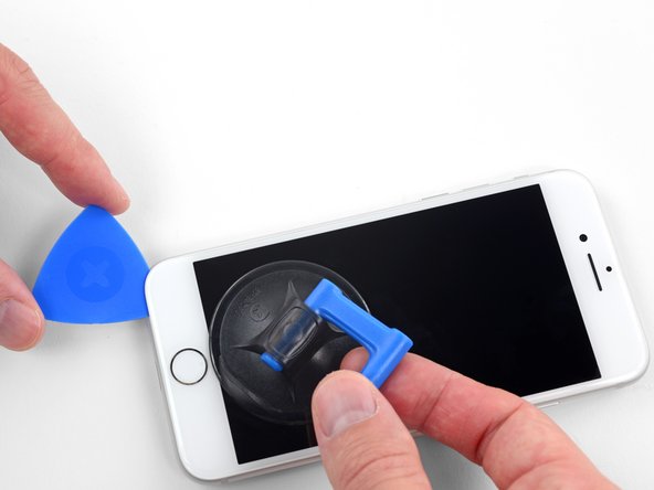
Get ready to put those muscles to work! The watertight adhesive is holding on tight, but no match for your determination. Apply some heat to spice things up, then gently groove the screen back and forth to loosen that grip. Before you know it, you’ll have created the perfect opening to slide in your trusty tool.
– Give that suction cup a good tug with steady pressure to create a tiny gap between the screen and the frame.
– Slide an opening pick into the gap.
Step 11


Remember, gently detach the top edge of the display from the rear case to avoid any breakage, as it’s secured in place by delicate plastic clips.
– Gently slide that trusty opening pick along the left edge of your phone, starting from the bottom and heading up towards those volume control buttons and the silent switch. You’re doing great at loosening up that adhesive that’s keeping the display snug as a bug!
– Awesome! Now, pause just shy of the top left corner of the display.
Step 12

Watch out! There are delicate cables along the right edge of your iPhone. Keep your pick away from here to avoid damaging them.
Step 13


– Let’s spice things up a bit! Pop your tool into the cool lower right corner of your iPhone. Then, smoothly slide it around that corner and up the right side of the phone to gently separate the adhesive.
Step 14


– With a gentle touch, lift that suction cup to raise the bottom edge of the display. You’re doing great!
– Next, give that small nub on the suction cup a little tug to pop it off the front panel. Smooth move!
Step 15


– Gently slide a cool opening pick under the display around the top left corner and along the top edge of the phone to loosen up the last of that adhesive.
Step 16


– Gently slide the display assembly down (away from the top edge of the phone) to unhook the clips holding it to the rear case.


Step 18

– Time to get those Phillips screws out! Start by removing the four screws that are holding the lower display cable bracket snugly against the logic board. Each screw comes in different lengths, so keep an eye on them!
– As you dive into this repair, remember to keep track of your screws. Each little guy has a special spot to return to during reassembly, and putting one in the wrong place could lead to some unwanted drama.
– Now, gently take off the bracket and set it aside. You’re doing great!
Step 19

– Get ready to show that battery connector who’s boss by using the point of a spudger to carefully pry it out of its socket in the logic board.
– Give that battery connector cable a little space from the logic board to avoid any accidental power trips as you work your magic. You’ve got this!
Tools Used

Step 20


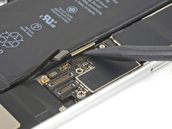
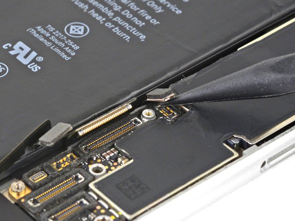
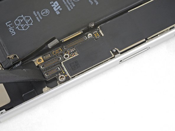
– Grab your trusty spudger and gently nudge the lower display connector out of its cozy little socket. It’s like giving it a friendly poke!
– When it’s time to reconnect, simply press down gently on one side of the connector until you hear that satisfying click. Then, do the same for the other side. Remember, no middle pressing allowed! If things are even a tad off, the connector might just get a little bent out of shape, and we don’t want that. So, let’s keep it straight and safe!
Tools Used
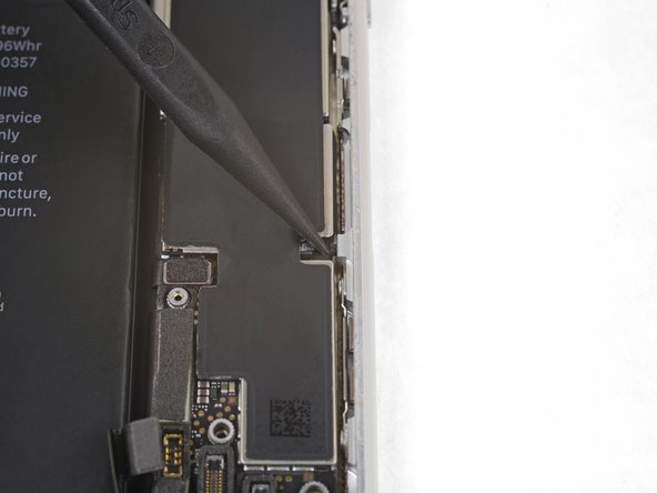
Step 21


– Grab your trusty spudger and gently pop off the second lower display cable. If you need help, you can always schedule a repair.
Tools Used
Step 22


– Let’s get started by unscrewing those three 1.3 mm Phillips screws that are holding down the bracket over the front panel sensor assembly connector. You got this!
– Now, go ahead and lift off the bracket. Easy peasy!


Step 25

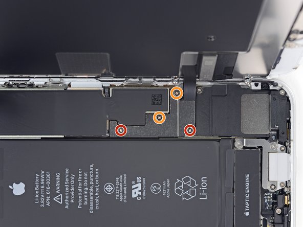
– Let’s get started by removing the three screws that are holding the bracket right next to the Taptic Engine:
– Grab your trusty 1.3 mm Y000 screw, it’s the little guy in the mix.
– Next up, we have a 2.7 mm Phillips screw, a bit bigger but just as important.
– Last but not least, say hello to the 2.9 mm Phillips screw, the biggest of the trio!
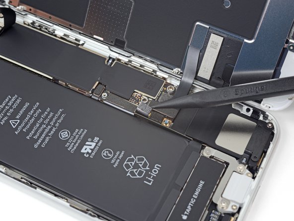
Step 26

– Get the bracket out of there!
Step 27


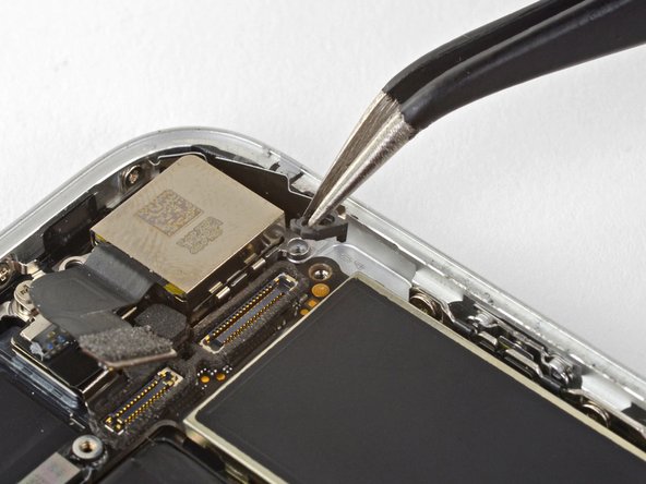
– Carefully slide an opening pick in between the antenna flex cable and the top of the speaker. You’ve got this!
Step 28


– Grab your trusty spudger and gently nudge up that diversity antenna flex cable to disconnect it from the logic board. You’ve got this!
Tools Used
Step 29


– Gently slide an opening pick beneath the antenna flex cable to keep that socket in place.
– Now, grab your trusty spudger and use its pointy end to carefully pry up and disconnect the antenna flex cable from its socket, while the opening pick holds the socket steady.
Tools Used
Step 30

– Let’s jazz it up a bit by removing the Wi-Fi diversity antenna.

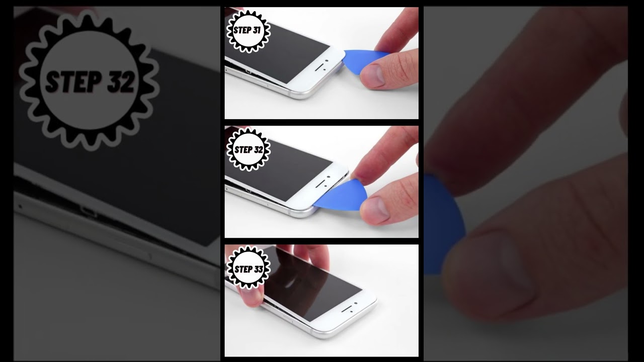
Step 32


– Use your trusty spudger to lift the antenna cable socket gently away from the connector below it. If you need help, you can always schedule a repair.
Tools Used
Step 33


– Grab your trusty spudger and gently lift to disconnect the Taptic Engine flex cable. If you need help, you can always schedule a repair.
Tools Used
Step 34

Watch out when you’re taking off that Taptic Engine flex cable! It might be a little too cozy with the antenna flex cable, so give it a gentle nudge.
– Let’s groove on over and gently detach the Taptic Engine.
Step 35

– Unscrew the two screws that are holding the barometric vent snugly to the back case. You’ve got this!


Step 37

– Time to pop off that barometric vent!
Step 38


– Grab that trusty spudger and gently lift the camera cable connector straight up from its socket. Remember, if you need help, you can always schedule a repair.
Tools Used
Step 39

– Get ready to bid farewell to those two pesky screws holding back the rear-facing camera bracket:
Step 40

– Let’s get started by carefully taking off the rear-facing camera bracket. You’ve got this!


Step 42

– Unscrew the two screws holding the upper cable bracket in place:
Step 43

– Time to say goodbye to that upper cable bracket. Just gently remove it and keep moving forward!


Step 45

– Take out the three 1.3 mm Phillips screws holding down the top-left antenna part. If you need help, you can always schedule a repair.
Step 46

– Get ready to rock ‘n roll by unscrewing the 1.4 mm Phillips screw that’s holding the antenna component snug at the top edge of the case.
Step 47

– Let’s get ready to detach that antenna component!
Step 48

– Unscrew those two Phillips screws holding down the grounding clip at the top left corner of the logic board. You’ve got this!
Step 49

– Get ready to set the grounding clip free!
Step 50

– Alrighty, let’s remove those three screws securing the motherboard! Just a little more and we’re on our way. If you need help, you can always schedule a repair.


Step 52

– Gently nudge that pesky SIM card eject plunger out of the logic board’s way with the tip of a spudger. It’s like giving it a little push to clear the path!
Tools Used
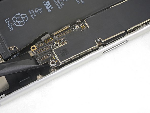
Step 53

– Grab your trusty spudger and gently wiggle it in to lift and disconnect the Lightning connector cable from the logic board. You’re almost there!
Tools Used
Step 54

– Gently use the tip of a spudger to lift and disconnect that wireless charging coil connector like a pro!
Tools Used
Step 55
– Grab the flat end of a spudger and gently nudge the battery connector end of the logic board up.
Tools Used
Step 56


Watch out for those sneaky cables trying to tangle up with the logic board.
– Grab the edges and gently lift the logic board near the battery connector to pop it out like a pro!
Step 57

– Unscrew those two screws holding the speaker snugly to the rear case!
Step 58

– Take out the speaker.
Step 59

– Unscrew those three little screws holding the Lightning connector cable tight and give it the freedom it deserves!
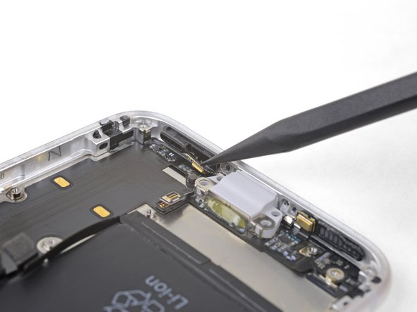
Step 60

– Unscrew the two tiny 1.4 mm Phillips screws that are holding the Lightning port snugly to the bottom edge of your phone. You’re doing great—keep it up!
Step 61

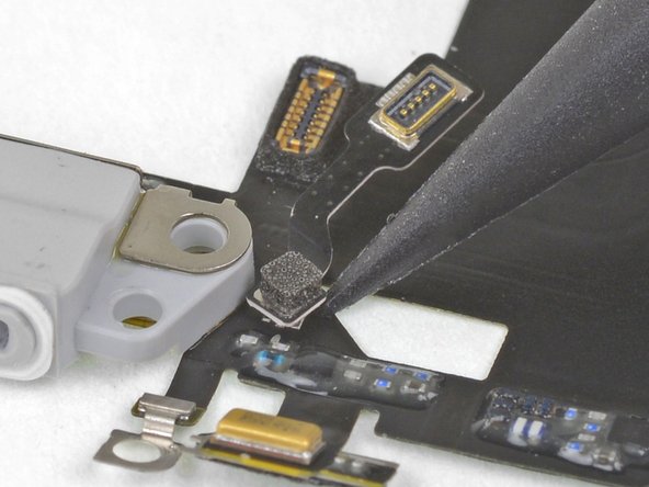
Just ease off the adhesive around the microphone, no need to fully remove it.
– Gently use the tip of a spudger to wiggle the logic-board-side microphone free from the adhesive holding it down. If you need help, you can always schedule a repair
Tools Used


Step 63

– Heat up that iOpener and apply it to the bottom of your phone. Tilt it as shown. This will help loosen the flex cable adhesive. If you need help, you can always schedule a repair.
Tools Used
Step 64
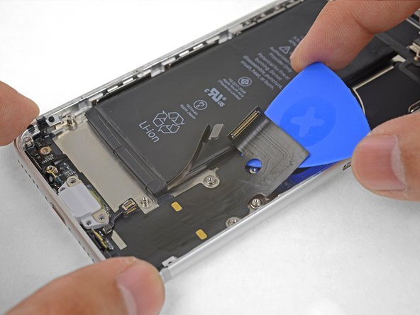

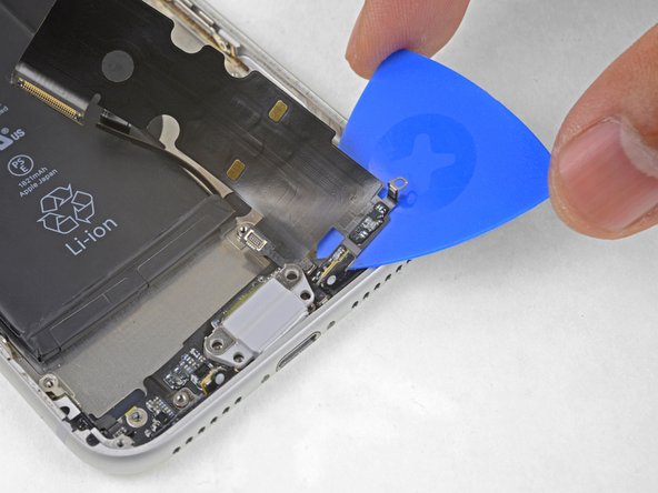
– Take an opening pick and sneak it under the top part of the Lightning connector assembly flex cable. Start gently prying the cable from the rear case.
– Carefully guide the pick towards the outer edge of your iPhone (away from the battery).
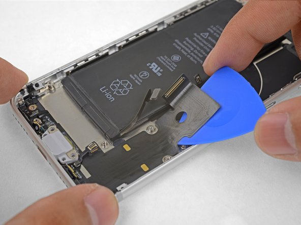
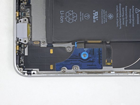
Step 65


– Keep separating the top part of the flex cable, making sure you don’t mess with any other bits on the way.
– Pause sliding the pick once it’s past the bottom edge of the battery.
Step 66

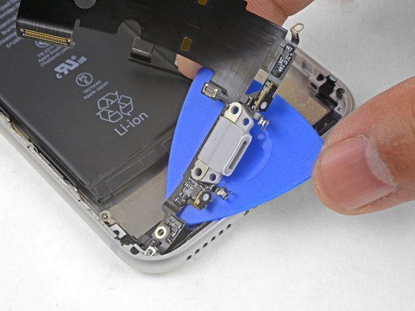
– Begin by sliding your trusty pick into the corner of your phone, gently working it under the cable as you inch your way toward the Lightning connector.
– Once you reach the Lightning connector, take a pause and stop sliding the pick. You’ve got this!
Step 67


– Carefully wiggle and ease the Lightning connector out of its cozy spot in the back case. You’ve got this!
Step 68

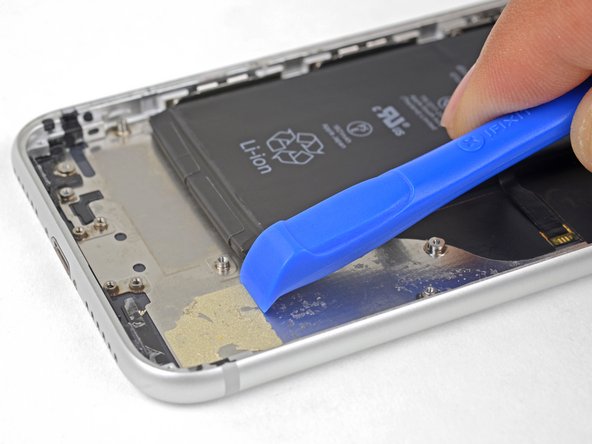
– Gently slide an opening pick under the Lightning connector to start loosening the assembly from the rear case.
– Keep sliding the pick along until the Lightning connector assembly is completely free from the bottom of the rear case.
Step 69


– Wiggle an opening pick between the left side of the case and the still-stuck part of the Lightning assembly. If you need help, you can always schedule a repair
Step 70

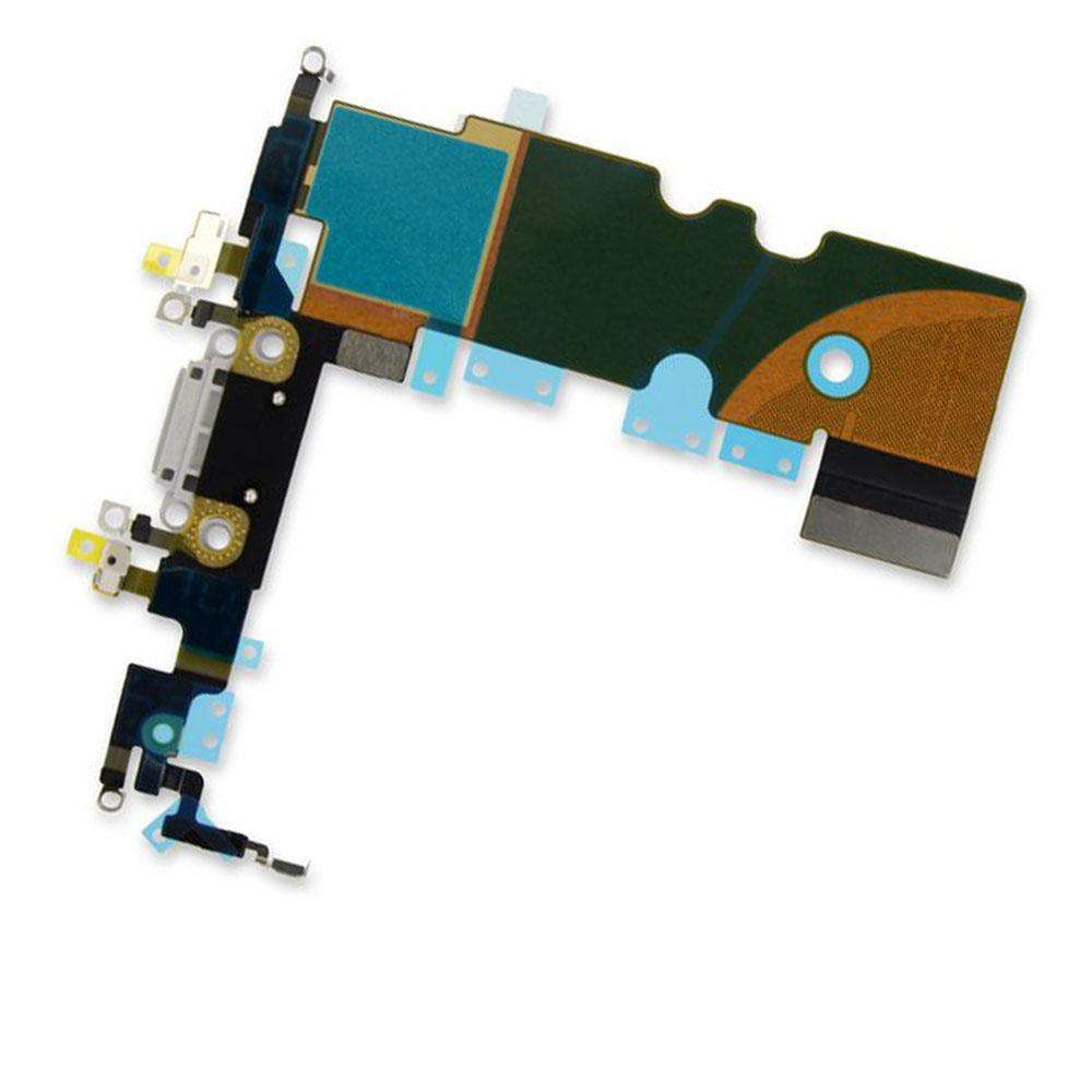
– Take out the Lightning connector assembly.
– Before getting your hands on installing or replacing the Lightning connector assembly:
Step 71

– There’s a handy little rubber gasket chilling at the bottom of the Lightning connector, keeping your iPhone safe from pesky liquid and dust. If you’re putting in a shiny new Lightning connector assembly, make sure to gently remove the gasket and give it a new home on the new part.
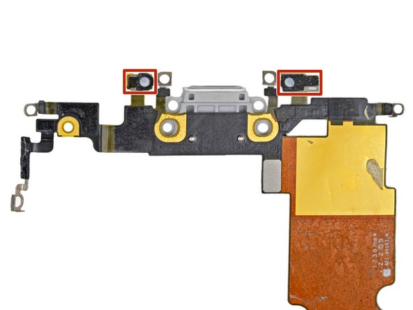
– Those tiny adhesive patches on the bottom of each microphone are like little shields for your iPhone against liquid and dust. For the best performance, swap out those two adhesive patches before you install your Lightning connector assembly.
– Take a peek to see if your new part includes an antenna converter cable. If it’s not in the package, don’t fret! Just use the tip of your spudger to carefully pop the cable off your old Lightning assembly and transfer it to the new one.
Tools Used