
iPhone SE 2022 Lightning Connector Assembly Replacement
Duration: 45 minutes
Steps: 67 Steps
Follow this guide to swap out or replace the Lightning connector assembly on your iPhone SE 2022. This assembly includes the lower microphones, an antenna converter cable, and, of course, the Lightning connector. If cleaning the port didn’t do the trick, swapping out the Lightning connector might just solve your charging and connectivity woes. This guide was tested on the A2783 (international) model. Just a heads up—if you don’t replace the adhesive seals during reassembly, your device will still work just fine, but you might lose some water resistance. You’ll need fresh adhesive to get everything sealed back up properly when putting it all back together. If you need help, you can always schedule a repair.
Step 1


- Grab a SIM card eject tool, a SIM eject bit, or even a straightened paper clip and gently poke it into the tiny hole on the SIM tray located on the right edge of your phone.
- Give it a steady press right into the hole to pop out the SIM card tray.
- Carefully pull out the SIM card tray and set it aside.
Tools Used

Step 2


- First things first: shut down your phone before you start taking it apart. Trust me, your device will thank you.
- Flip your iPhone over and unscrew the two 3.4 mm P2 pentalobe screws at the bottom edge. Keep those tiny screws safe—they love to disappear!
Step 3


Be careful not to insert the pick too far—this can lead to damage. Use this step to mark your pick and avoid any mishaps.
You can also mark the other corners of your pick with different measurements for extra precision.
Another trick is to tape a coin 3mm from the tip of the pick. Works like a charm!
- Mark the opening pick exactly 3 mm from the tip using a permanent marker—precision is key, so grab that marker and make your mark!
Step 4


Don't forget to wear your safety glasses! They'll keep your eyes safe from any pesky glass pieces that might come loose during the repair.
If your iPhone's screen has taken a hit and is cracked, don't worry! Just grab some tape and cover that glass to keep any further breakage in check and avoid any accidental pokes during your repair.
And if you're feeling adventurous, you can stick that suction cup right onto the screen with some superglue. Just a little extra hold to make your repair journey smoother!
- Cover the entire iPhone screen with overlapping strips of clear packing tape—think of it like wrapping a tiny, fragile present.
- If the suction cup refuses to stick in the upcoming steps, no worries! Grab a strong tape like duct tape, fold it into a little handle, and use that to gently lift the screen instead.
Step 5


The next three steps will introduce you to the Anti-Clamp, our nifty little tool designed to make opening your device a breeze. If you don't have an Anti-Clamp handy, no worries! Just skip down three steps for a different method.
Want to master the Anti-Clamp? Check out this handy guide for all the details!
If your iPhone's surface is feeling a bit too slick for the Anti-Clamp to grip, a little tape can work wonders to create a better hold.
- Give that blue handle a gentle pull backward to unlock the Anti-Clamp’s arms.
- Slide the arms over either the left or right side of your iPhone—whatever feels right.
- Line up the suction cups just above the home button at the bottom edge, with one on the front and one on the back.
- Squeeze the cups together to get a good grip right where you need it.
Step 6


- Slide the blue handle forward to lock those arms in place—nice and snug.
- Spin the handle clockwise all the way around (yep, a full 360) or until you see the cups starting to stretch.
- Keep an eye on those suction cups! If they start to drift apart, just loosen them a bit and realign the arms to keep everything working together.
Step 7


Take it easy and don't go twisting more than a quarter turn at once. Give it a minute to breathe between those turns. Let the Anti-Clamp and time do their magic for you!
Got a hair dryer, heat gun, or hot plate? Great! Just be careful, because too much heat could mess with the display or the internal battery. Take it slow and steady.
If the Anti-Clamp isn't creating enough of a gap, no worries—just apply a bit more heat to the area and give the handle a quick quarter turn. Patience is key!
- Warm up an iOpener and slide it through the arms of the Anti-Clamp.
- Fold the iOpener so it rests along the bottom edge of your iPhone.
- Give it a minute to soften the adhesive and create a little gap for prying.
- Gently slide an opening pick under the screen's plastic bezel—avoid the screen itself.
- Skip the next two steps.


Step 8

If you're working with a suction handle, go ahead and tackle the next two steps to gently free the rear glass.
You can also use a hair dryer, heat gun, or hot plate to warm things up—but take it easy! Overheating can harm the display and battery, so keep it cool while heating.
- Grab your iOpener and give the screen a nice warm hug for at least two minutes. This will help loosen up the adhesive underneath so you can tackle the next steps with ease.
Tools Used

Step 9


If you're finding it tricky to create a gap, don't fret! Just warm up the bottom half of the screen a bit more to help loosen that adhesive. Remember to check the iOpener instructions to keep everything at the right temperature. You've got this!
- Attach a suction handle to the lower part of the front panel, aiming for a spot as close to the home button as you can manage.
- Gently pull up on the suction handle to lift the front panel just enough to create a little gap between the screen and the frame.
- Slide an opening pick into that gap under the plastic bezel around the screen. Take it slow and steady—patience is key!
Tools Used
Step 10


- Gently slide the opening pick to the bottom right corner to expertly cut through that pesky front panel adhesive.
- Now, pop in a second opening pick at the bottom edge of your phone for some extra support.
- Keep that momentum going by sliding the opening pick to the bottom left corner, slicing through the adhesive like a pro.
- Don't forget to leave those opening picks in place—they're your adhesive-stopping heroes, preventing any unwelcome resealing.
Step 11


Hey there! Just a heads up: don't go yanking at the top edge of that display to separate it from the rear case. It's got some sneaky plastic clips holding it tight, and we wouldn't want those little guys to snap on you.
If the adhesive is giving you a hard time, it probably means it's lost some heat. No worries! Just grab your iOpener and give it a little love for two to three minutes to warm things back up.
- Gently slide the bottom-left pick along the left edge of your device to break through the adhesive. Go slow and steady!
- Stop just before reaching the top-left corner of the screen. You're almost there!
Tools Used
Step 12


Keep your pick's depth under 3 mm—anything deeper might cause some unexpected damage to the inside parts.
- Gently glide the bottom right opening pick along the right edge of your phone to break the adhesive seal.
- Pause just before reaching the top right corner of the display.
Step 13


Be careful not to tilt the display more than 15º! Going past that can put a strain on those delicate ribbon cables and risk damaging them.
- Take out those opening picks.
- Carefully lift the bottom edge of the display by pulling up on the suction handle.
- Then, go ahead and remove the suction handle.
Tools Used
Step 14


- Gently slide an opening pick beneath the top left corner of the display, like you're sneaking in a little surprise.
- Carefully slide the opening pick around the top left corner and along the top edge of the phone to slice through any stubborn adhesive that's still holding on.
Step 15


- Gently slide the display assembly downward toward the charging port to pop the clips free from the rear case.
Step 16


Hold up! Don't completely detach the display from the phone just yet. There are still a few delicate ribbon cables connecting it to the logic board, and you don't want to mess those up.
- Gently lift the display up from the left side, just like opening a book. Easy peasy!
- Rest the display against something sturdy to keep it up and out of your way while you work on the phone.
Step 17

- Start by unscrewing the four Phillips screws that hold the lower display cable bracket in place.
- As you work through this guide, keep a close eye on those screws. You’ll want to put each one back where it belongs during reassembly. Putting a screw in the wrong spot could cause some serious issues down the line.
- Two screws are 1.2mm long
- Two screws are 2.8mm long
Step 18


- Grab your trusty tweezers and gently lift away the lower display cable bracket. You've got this!
Tools Used

Step 19


- Grab the pointy end of your spudger and gently lift the battery connector straight up out of its socket—think of it like popping a cork, nice and steady!
Tools Used

Step 20


The display and digitizer cables like to hang out on top of each other. To keep them from getting all tangled up, always start by disconnecting the upper cable first. Never try to disconnect both cables at once—your cables will thank you!
- Grab the pointed end of your spudger and carefully pop up the bottom two display cable connectors by gently prying them straight up from their sockets.
- When it’s time to reconnect, press down on one side of the connector until you hear a click, then do the same on the other side. Avoid pressing the middle area—if the connector isn’t perfectly lined up, pressing there can bend it and cause permanent damage.
Tools Used
Step 21

- Grab your trusty Phillips screwdriver and take out those three little screws, each measuring 1.2 mm long, that are keeping the front sensor assembly bracket in place. You've got this!
Step 22


- Grab a pair of tweezers and gently lift off the front sensor assembly bracket. Take your time, and be careful not to rush through it.
Tools Used
Step 23


- Gently use the pointed end of a spudger to lift the front sensor assembly connector straight up from its socket. You've got this!
Tools Used
Step 24


- Gently detach the display assembly and set it aside carefully.
Step 25

- Loosen up the three screws holding down the Lightning connector bracket:
- One Y000 screw, 1.2 mm long
- One Phillips screw, 2.7 mm long
- One Phillips screw, 2.9 mm long
Step 26


- Grab your trusty tweezers and delicately lift out the Lightning connector bracket. You've got this!
Tools Used
Step 27


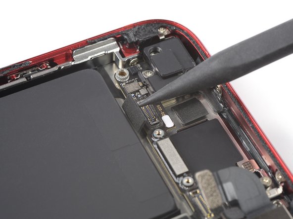
This part of the flex cable is gently stuck to the speaker. If you find it tricky to detach the cable from the speaker, a little warmth from an iOpener or hair dryer can help loosen the adhesive. This will make it much easier to safely separate the flex cable.
- Gently slide an opening pick between the antenna flex cable and the top edge of the speaker to carefully separate them.
Tools Used
Step 28


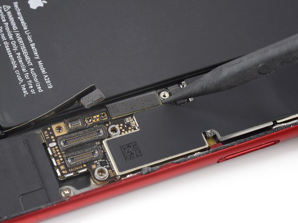
The connector socket can be a bit tricky to deal with, sitting loosely between the speaker and Taptic Engine. It's not the easiest cable to disconnect. To make life a little easier, try using an opening pick to gently hold the connector socket in place as you work through it.
- Grab your trusty spudger and use its pointed end to gently pry the Wi-Fi diversity antenna connector straight up from its socket. It's a little like a game of tug-of-war, but trust us, you're the champion here!
- Reconnecting this little cable can feel like a puzzle, but don’t worry! Use tweezers to hold the flex cable steady while you line up the connector with its socket. Once they're best buddies, press down gently on the connector with the flat side of your spudger until you hear that satisfying click. You've got this!
Step 29


- Grab the pointy end of your spudger and gently pry the Wi-Fi diversity antenna connector straight up off the logic board socket. Take it slow and steady!
Tools Used
Step 30


- Grab your tweezers and gently lift that Wi-Fi diversity antenna out of its cozy spot.
Tools Used
Step 31

If you're in a jam, a tiny flathead screwdriver can save the day—but be super careful to keep it steady so it doesn't slip and cause trouble for your other components.
The best way to tackle those standoff screws is with a standoff screwdriver or bit—makes the job way smoother!
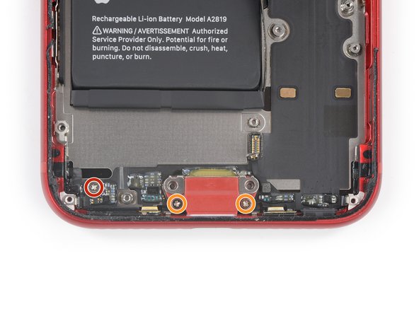
- Let's get those screws out and free the Taptic Engine! Start by removing two screws:
- One 2.1 mm Phillips screw, which is a little twisty friend, and
- One 2.1 mm standoff screw that’s just hanging out waiting to be removed.
Step 32


- Grab a trusty pair of tweezers and gently lift off the grounding bracket located at the left side of the Taptic Engine. You're doing great!
Tools Used
Step 33


- Gently use the pointy end of your spudger to lift the antenna cable socket up and away from the Taptic Engine connector hanging out below. You've got this!
Tools Used
Step 34


- Grab the pointy end of your spudger and gently pop the Taptic Engine connector straight up out of its socket. Easy does it!
Tools Used
Step 35


- Grab a pair of tweezers and gently lift the Taptic Engine out of its spot. No rush, just take it slow and steady!
Tools Used
Step 36

- Loosen up and take out the two screws holding the barometric vent in place:
- One 1.9 mm Phillips screw
- One 1.7 mm Phillips screw
Step 37


The barometric vent is gently stuck to the back case. If it’s being stubborn and won’t come off easily, try warming it up a bit with an iOpener or hair dryer to loosen the adhesive. This makes popping the vent off a breeze without any drama.
Step 38


- Gently use the pointed end of a spudger to lift the rear camera connector straight out of its socket. Be careful not to rush—patience is key here!
Tools Used
Step 39

If you're in a bind, a tiny flathead screwdriver can save the day—but be extra careful to avoid any slips that might mess with your precious components.
To tackle those standoff screws like a pro, grab yourself a standoff screwdriver or bit. You've got this!
- Unscrew the two little guys holding down the rear-facing camera bracket:
- One 3.0 mm-long standoff screw
- One 3.1 mm-long Phillips screw


Step 41


- Gently use the pointed end of a spudger to lift the flash connector straight up from its socket. You've got this!
Tools Used
Step 42

- Time to get those screws out! Start by loosening the two screws that are holding the upper cable bracket in place:
- One 2.8 mm Phillips screw (not too tight, just enough to let go)
- One 1.2 mm Phillips screw (a tiny one, but important!)
Step 43


- Grab those trusty tweezers and gently lift off the upper cable bracket. You've got this!
Tools Used
Step 44

- Grab your trusty spudger and use its pointed end to gently lift the upper flex cable connector straight up from its socket. You've got this!
Tools Used
Step 45

Hold up! Don’t yank out that antenna just yet—there’s a sneaky fourth screw still holding it tight to the rear case.
- Remove the trio of 1.2 mm Phillips screws hanging out with the top left antenna—don’t let them crash the party any longer!
Step 46

- Loosen the 1.4 mm Phillips screw holding the antenna part to the top edge of the back case. Keep it safe!
Step 47


- Grab a pair of tweezers and gently lift off the top left antenna component. Take your time and be steady, it’s a small step that’ll make a big difference!
Tools Used
Step 48

- Let's get those screws out and free the top left grounding bracket! Here's what you'll need to do:
- Remove one 1.5 mm-long Phillips screw.
- Then, take out one 1.2 mm-long Phillips screw.
Step 49


- Grab your tweezers and carefully lift off the top left grounding bracket.
Tools Used
Step 50

This little screw is hiding behind some protective foam around the rear camera connector. Grab a pair of tweezers and gently peel back just enough foam to reveal the screw and get it unfastened. You've got this!
- Loosen and remove the four screws holding the logic board in place:
- One 1.7 mm Phillips screw
- One partially threaded 1.7 mm Phillips screw
- One 2.5 mm standoff screw
- One 2.2 mm standoff screw
Tools Used
Step 51


- Grab a pair of tweezers and gently lift the logic board grounding bracket from the top right corner of the rear case. Take it slow and steady—you've got this!
Tools Used
Step 52


- Grab your trusty spudger and gently use the pointed end to nudge that SIM card eject plunger out of the way! Just slide it over to the right edge of the rear case, and you're all set!
Tools Used
Step 53


- Grab your spudger and gently use the pointed end to pop the Lightning port cable free. Just lift the connector straight up from its socket, no fancy moves needed.
- Now, grab the spudger again and carefully detach the wireless charging coil cable. Use the pointed end to lift the connector straight up from its socket—easy does it.
Tools Used
Step 54


Watch out for cables—don't use your pry tool on them! If something feels stuck, double-check that all cables, connectors, and parts are free and clear before moving on.
- Take the flat end of your spudger and gently lift up the battery connector end of the logic board. No rush—just a smooth and steady move!
Tools Used
Step 55


Double-check that none of the cables nearby are getting in the way of the logic board. We don't want any tangled messes causing a delay!
- Gently grab the logic board by the edges, then carefully lift it near the battery connector and slide it out. You've got this!
Step 56

- Time to get those speakers free! Start by loosening up the two screws holding them in place:
- One Phillips screw that's 1.4 mm long
- And another Phillips screw measuring 2.1 mm long


Step 58

- Loosen the five screws holding the lighting connector onto the back case:
- One Phillips screw, 1.3 mm long
- Two Phillips screws, each 2.3 mm long
- Two Phillips screws, each 1.4 mm long
Step 59


Just gently peel away the adhesive from the microphones—no need to completely remove them!
- Grab your trusty spudger and use its pointed end to delicately lift the two microphones located on either side of the Lightning connector, freeing them from their adhesive bonds. You've got this!
Tools Used
Step 60

- Heat up that iOpener and give the bottom of the rear case a warm hug! This will help loosen the adhesive holding the charging port assembly. Just angle it like shown and let the magic happen.
Tools Used
Step 61

Watch out! There's a sneaky part of the wireless charging coil hiding right under this section of the Lightning connector flex cable. If you pry too hard, you might give it a bad day!
Keep the battery connector gently tucked away to keep it safe and sound. We don’t want any surprises here!
Be super cautious with the battery! If it gets punctured, it can spill some nasty stuff and even go up in flames. Let's keep it chill!
If the adhesive is being stubborn, give it another round of heat with your hair dryer or iOpener to soften things up behind the Lightning connector assembly flex cable.
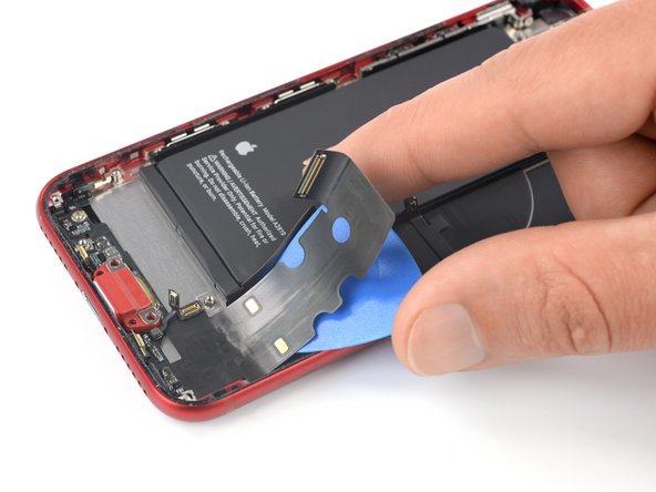
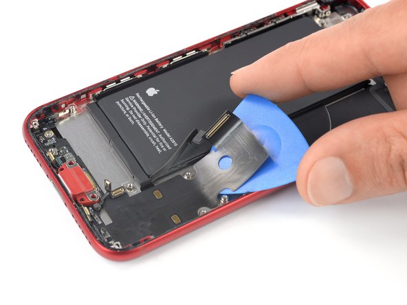
- Slide your opening pick under the top part of the Lightning connector assembly flex cable, and start gently lifting it away from the rear case.
- Keep going with the separation, just be extra careful around those other components—no need for any accidental damage!
- Once you’ve passed the lower edge of the battery, stop sliding the pick. You’ve made it past the tricky part!
Tools Used
Step 62


- Kick things off at the corner of your phone and gently slide that pick right under the cable, making your way towards the Lightning connector.
- Once you hit the Lightning connector, it's time to hit the brakes on that pick sliding action.
Step 63


Hold up! Don’t yank out the lightning connector assembly just yet—it’s still sticking to the rear case a bit.
- Carefully wiggle and pull the Lightning connector out of its cozy little spot in the back case. You've got this!
Step 64


You're almost there! But don’t go too fast—there's still a little bit of the lightning connector hanging on to the left side of the rear case. Gently work it loose before moving on.
- Slide an opening pick underneath the Lightning connector to help free the assembly from the rear case.
- Keep sliding that pick until the Lightning connector assembly is completely detached from the bottom of the rear case.
Step 65


- Gently slide an opening pick along the left edge where the rear case meets the still-stuck part of the Lightning assembly.
Step 66


Before peeling off that adhesive backing on your fresh new assembly, double-check that the Lightning connector assembly is lined up just right. The hole in the flex cable should match up with the screw post. If it's off, you won't be able to reconnect it to the logic board—so take a sec to make sure everything's aligned!
- Take out the Lightning connector assembly.
- Before popping in a new Lightning connector assembly:
- Scrape off any leftover adhesive and give the glued spots a good clean with isopropyl alcohol and a lint-free cloth.
Step 67


- If you can, power up your device and give your repair a quick test before sticking down new adhesive and sealing it up.
- Make sure your new replacement part matches the original—sometimes you’ll need to move over a few leftover components or peel off extra adhesive strips before putting it in place.
- To put your device back together, just follow these steps in reverse.
- Don’t forget to recycle your e-waste responsibly at an R2 or e-Stewards certified facility.
- If things didn’t go quite as planned, try some basic troubleshooting or consider scheduling a repair for expert help.


