
iPhone X Bottom Speaker Repair
Duration: 45 minutes
Steps: 9 Steps
Step 1


- We've got a phone with a shattered screen and a squished frame. Pop in a fresh display assembly and fire it up. Everything powers on like a champ. Both cameras are snapping, and WiFi is cruising.
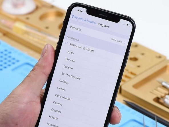
- Jump into Sounds & Haptics > Ringtone. Pick a classic ringtone—crickets from the speaker, but plug in some headphones and the sound is rolling.
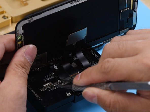
- At first glance, the audio circuit seems to be behaving. The real culprit? The bottom speaker isn't doing its thing. Unscrew the display assembly and unhook the battery.
- Unplug the charging port flex cable. Time for some detective work: check Pin 1 and Pin 45 on the DOCK connector using diode mode. If you get a reading of 5, the bottom speaker is all good.
Step 2


- Keep going and measure Pin 1 and Pin 45 on the motherboard connector J6400. Pin 45 should show a value of 602 — that's a good sign.
- Pin 1 is showing 'OL' though, which means something's off. Time to check further!
Step 3

- Looks like Pin 1's circuit decided to take a little break—it's open-circuited. Pin 1 on connector J6400 links up to Pin 2 on the speaker amplifier IC U4900 through Pin S162 on the cylinders around the lower layer’s edge.
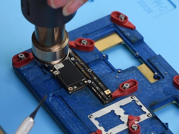
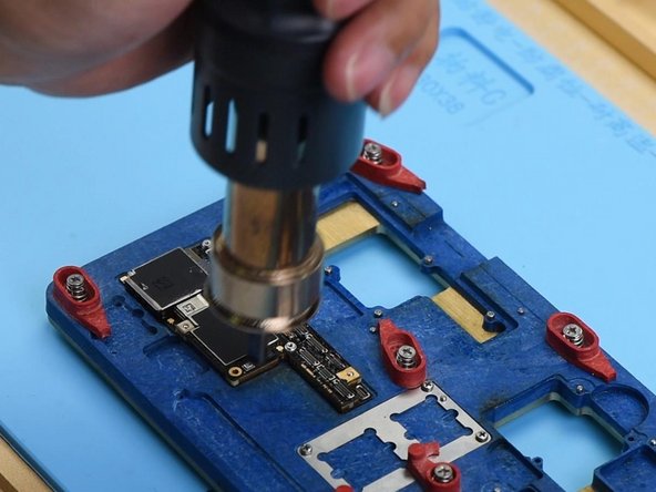
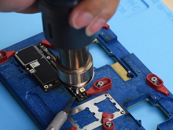
- Next up, let's give that circuit a thorough once-over. Start by unplugging the flex cables from the motherboard and removing the motherboard itself. Secure it in the Holder, then heat it up with a Hot Air Gun set to 360℃ and airflow at 65.
Step 4
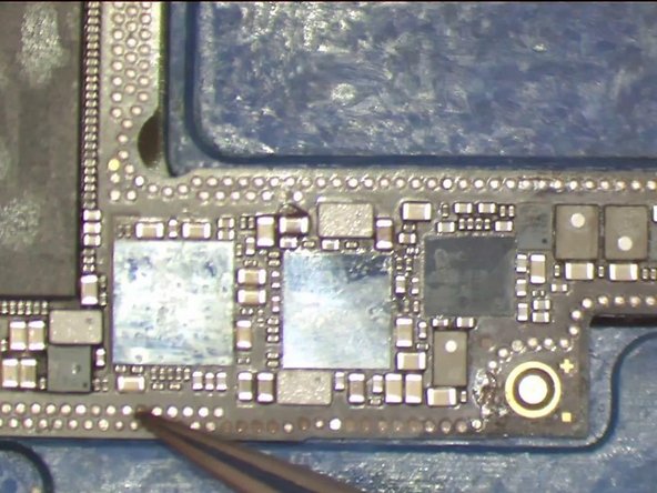

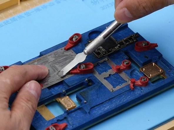
- After waiting a minute, gently start prying up the upper layer, taking it step by step. Pro tip: ensure you pry at just the right moment when the tin on the cylinders has melted. It’s pretty clear there are several pins missing from the upper layer, including the S166 pin from the NFC circuit. You've got this!
Step 5

- Looks like our phone took a little tumble, leading to some quirky soldering on the motherboard and some pins deciding to go AWOL. No worries, though! Most of those missing pins are just ground pins, so we can let them be. Just make sure to give some love to Pin S166 with a bit of jumper wiring.
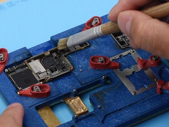
- Time to tidy up! Grab some rosin-soaked Solder Wick and gently remove the tins around the cylinders on the lower layer and the bonding pads on the upper layer. After that, give everything a good clean with some PCB Cleaner to keep it fresh!
Step 6

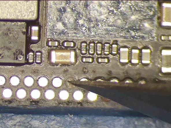
- Grab your multimeter and set it to diode mode. Hit Pin S162 on those cylinders—reading 570? Nice, that's totally in range. Next up, Pin S163? Another 570, looking good! At this point, it's pretty clear that Pin 1's open circuit is just some weak soldering around the edge of the lower layer cylinders.
- Alright, time to get that motherboard into the testing kit. Pop on the extension flex cable for the display assembly, then snap in the charging port flex cable and the display assembly. Smooth sailing so far!
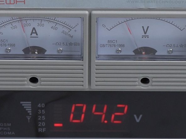
- Hook up the battery connector to the DC Power Supply. Use tweezers to short Pin 9 of J4300 to ground—this tricks the system into thinking you’ve pressed the power button. Check the ammeter; if the current looks normal, you're all set!
Step 7

- Head over to Settings > Sounds & Haptics > Ringtone. Pick a default ringtone that suits your vibe. The sound should be working fine now.
- All right, we’ve got confirmation! The top and bottom layers are good to go. The issue was caused by some not-so-great soldering on the cylinders. Let’s fix that by properly soldering those two layers together. Before you start, don’t forget to treat Pin S166 with a jumper wire.
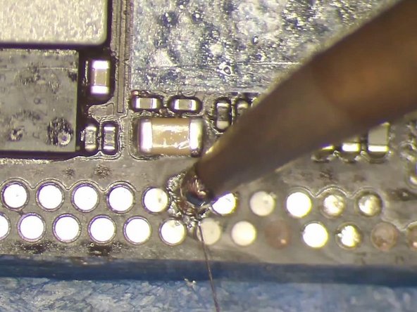
- Heat up your soldering iron to 360°C and get ready to apply some solder to the Via. Take a length of 0.02mm enameled copper wire, tin it, and solder one end to the Via. Now you're cooking!
Step 8

- First, grab some PCB Cleaner and give the area a good clean. Once that's done, grab some UV Curable Solder Mask and apply it to the soldered area. Pop it under the UV Dryer Lamp for about 2 minutes to let the upper layer solidify.
- Next, get the other end into position, and secure the lower layer to the PCB Holder. Place the BGA Reballing Stencil in the right spot, and then evenly smear the Soldering Paste on the stencil using the BGA Scraper. Use a lint-free cloth to wipe off any extra soldering paste.
- Now, it’s time to heat it all up with the Hot Air Gun. Set it to 350℃ and an air flow of 35. This will help all the solder balls solidify nicely. After 2 minutes, carefully remove the BGA reballing stencil. Give it another heat session with the Hot Air Gun to make sure those solder balls are perfectly formed.
Step 9

- Now that you've tackled the disassembly, it's time to put everything back together! Just follow these steps in reverse, and you'll be all set. If you run into any snags, feel free to schedule a repair for some extra support.


