Lenovo IdeaPad A1-07 Motherboard Replacement
Duration: 45 minutes
Steps: 13 Steps
Is your Lenovo IdeaPad A1-07 tablet on the fritz? If a software issue has left it unresponsive, the motherboard might be the culprit. Over time, these little guys can wear out from heavy use or even crack under pressure. Don’t worry, this step-by-step guide from Salvation Repair will walk you through the process of carefully disassembling your tablet to access and remove the motherboard. Before you start, make sure your device is powered off and unplugged from the charger. Let’s get started!
Step 1


When you’re about halfway there, give it a little thumb power to pop the rest of that back cover off!
– Grab the blue plastic opening tool and gently use the lock screen switch near the volume button as your starting point to lift the back cover off.
– Slide the opening tool in until you hear the satisfying pop of the back cover loosening from the device.
– Run the opening tool along the side of the device to keep it coming off smoothly.
Step 2


Take it easy when you’re removing the frame! Forcing it can lead to breaking the little teeth that hold it snugly to the screen. We want a smooth operation, not a disaster!
The gray frame remains connected to the device by a couple of wires that run from the motherboard to the speaker. So, don’t worry! You’re almost there—just give those wires a little respect as you work through the process.
– Grab your trusty Phillips #000 screwdriver and remove all 18 of those tiny 4mm screws – you got this!
– Time to get a little gentle – use your blue plastic opening tool to carefully pry the screen away from the gray frame until you hit some resistance. Easy does it!
– Now, take your opening tool and push those teeth towards the center of the device, then give the frame a gentle tug to remove it. You’re making great progress!
Tools Used

Step 3


The speaker nestled in the grey frame is linked to the motherboard via a snazzy white plastic connector.
– Time to disconnect the speaker! Simply pry apart the two sides of the speaker connector to release it.
Step 4
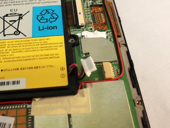
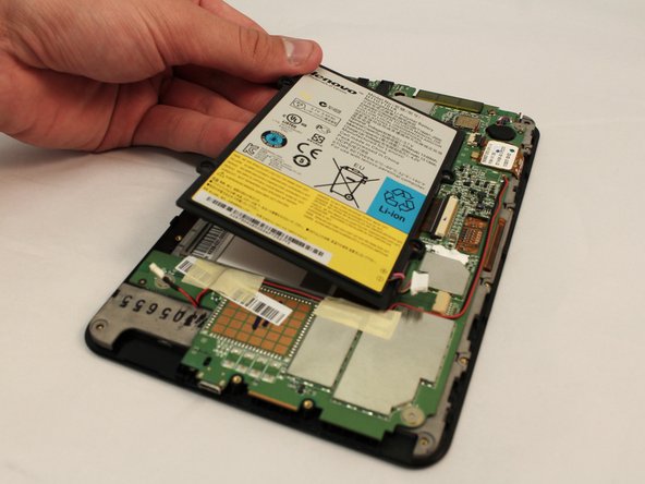

– Grab your trusty plastic opening tool and gently nudge that white battery connector right out of its cozy spot on the motherboard.
– Now, give the battery a little lift and say goodbye as you pull it away from the device.
Step 5

Time to disconnect all the connectors on the motherboard. Take your time, and remember, it’s all part of the process!
– Let’s kick things off by unscrewing those three 3 mm screws that are hanging onto the motherboard like they’re at a party. Grab your trusty Phillips #000 screwdriver and get to work!
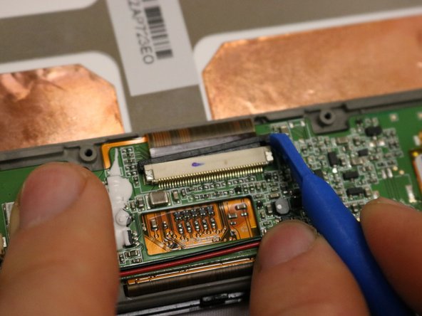
– Now, hunt for the connector right in the center of the motherboard, and give it a gentle pull to disconnect.
– Use your opening tool to slide that small black retainer out of the way—this will relieve some pressure on the brown ribbon cable. You got this!
– With a steady hand, pull that brown ribbon cable out of the connector using the edge of your opening tool. Nice and easy!
Tools Used
Step 6

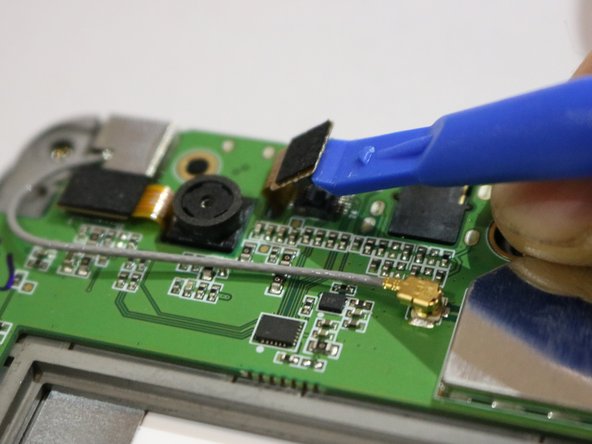
When it pops up and out of position, you’ve successfully disconnected it!
– Gently disconnect the connector next to the back camera by using a plastic opening tool. Just lift and pry it up with care, and you’re good to go!
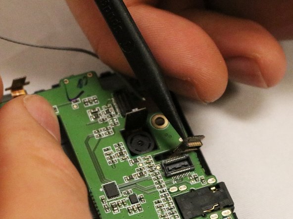
Step 7
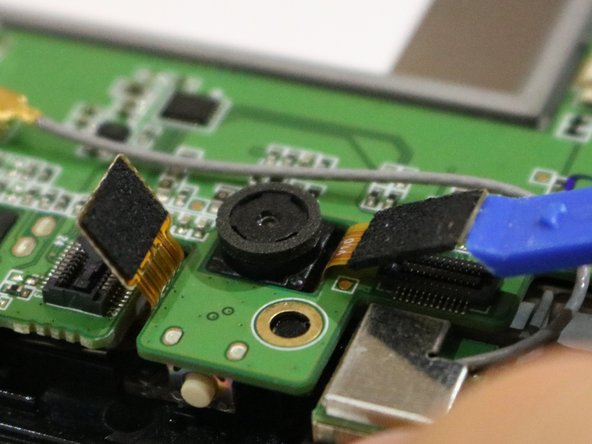

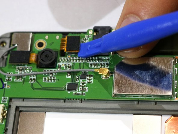
– Just like the previous connector, go ahead and disconnect the one to the left of the back camera. Simple as that!
Step 8

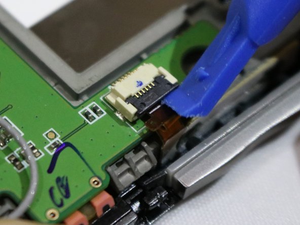
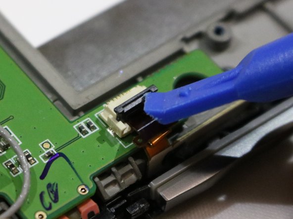
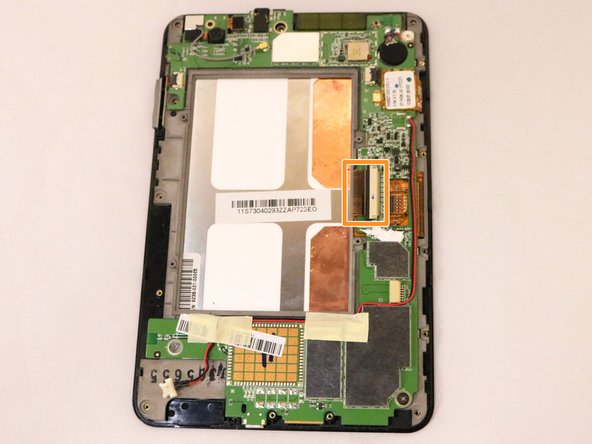
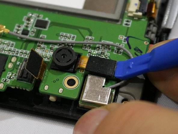
There’s another connector hiding at the top left of the motherboard, right next to the volume button. Keep an eye out for it!
– Grab your trusty opening tool and gently lift the black lever on the connector. You’ve got this!
– Now, take that same tool and carefully pull out the brown ribbon hiding underneath. Easy peasy!
Step 9
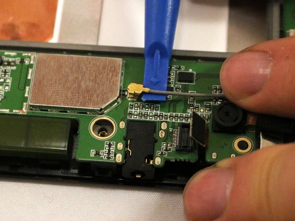
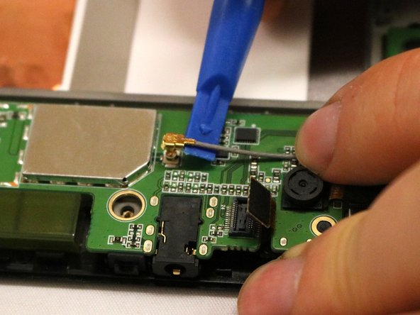

The last connector we’re dealing with is a snazzy grey cable sporting a golden tip, better known as the coaxial cable. It’s snugly fitted, so you might need to give it a little extra oomph to pop it out.
– Time to set that connector free! Slide the opening tool up to the base of the tip to disconnect the last one.
– Now, gently twist the opening tool to coax the coaxial cable out of its hiding spot.
Step 10
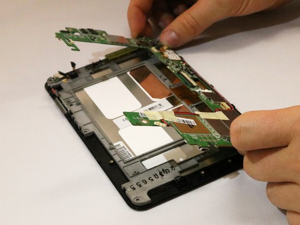

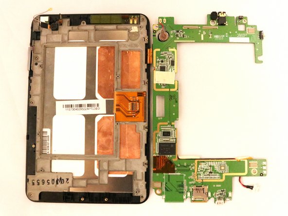
With the cameras facing up, keep an eye out for that one ribbon on the right side of the motherboard—it’s still connected to the screen and ready for action!
– Gently lift the motherboard while carefully pushing the connector heads back through their holes.
– Lift the motherboard from the left side and rotate it over to the right, like you’re flipping a page in a book.
Step 11

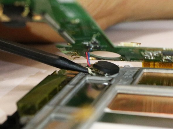
After you’ve deftly maneuvered all those connectors through, the final piece tethering the motherboard to the screen is the motherboard battery.
That connector is snugly secured to the metal frame with some sticky adhesive.
– Grab your trusty black spudger and gently wiggle it under the connector, giving a little tug at the base of the battery. You’ve got this!
Step 12
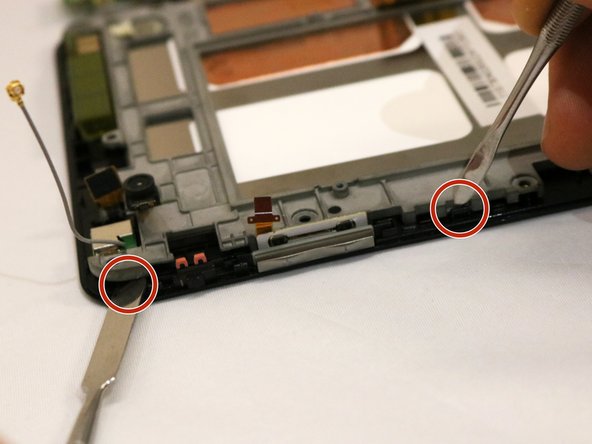
Now it’s time to say goodbye to that screen and detach it from the front cover like a pro!
Make sure to guide your tool straight down the side. There’s a delicate copper film in there that could get crumpled if the spudger sneaks in from the side. Keep it steady!
– Alright, flip that device over so the screen’s taking a little nap. Now, give a gentle tug on the top left corner of the metal frame while at the same time, coaxing out that pesky plastic tooth with two spudgers.
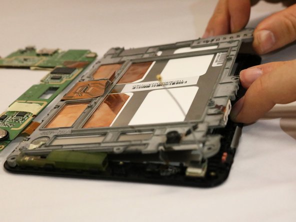
– Lift carefully until you sense that adhesive giving you a bit of a workout on the right side. You’ve got this!
– Once you feel that friendly tension, slide a spudger tool down the right side, like you’re peeling off a tasty sticker, to break free that adhesive.
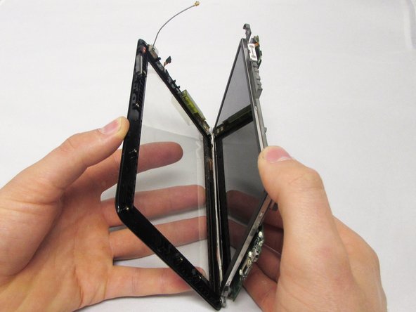
Step 13

Now that you’ve successfully removed the screen, it’s time to give it a new life with a replacement.
– The motherboard is affixed to the black screen frame using a cool orange film tab.
Success!