Lenovo IdeaTab S2109A-F I/O Panel Replacement
Duration: 45 minutes
Steps: 12 Steps
Popped in a micro SD card but your device is acting like it’s invisible? Sounds like the reader might be napping on the job. Here’s how you can remove the I/O panel and give that card reader the attention it needs. Let’s get your storage back in action!
Step 1


Power down your tablet before you get started—poking around inside while it’s on is a risky move!
– Flip the tablet onto its screen and grab your trusty opening tool to gently detach the back cover.
– With a little bit of pressure from the tool, coax the back panel to part ways with the tablet.
Step 2


– Let’s get started! Carefully grab the battery and gently pry it upwards – you should see a red and black coiled wire hiding underneath.
– Now, give the battery a gentle tug until the cord is taut, with no slack in it.
Step 3

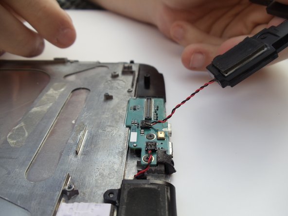
– Hold the battery steady in one hand while your other hand’s index finger and thumb take charge of the two wires closest to their connection point.
– Give the black and red wires a firm but controlled tug—no need for a power move here, just enough to disconnect them without harming the tablet.
– Lift out the battery like a pro, and you’ve successfully removed it from the device!
Step 4

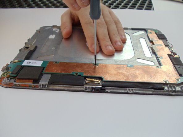
– Grab your trusty Phillips #00 screwdriver and carefully unscrew the ten 2 mm black screws that are holding the edges of the system board in place. You’ve got this!
Tools Used

Step 5

– Gently lift the latch with your plastic opening tool to disconnect the gold connector. It’s like a tiny pop! You’ve got this!
Step 6
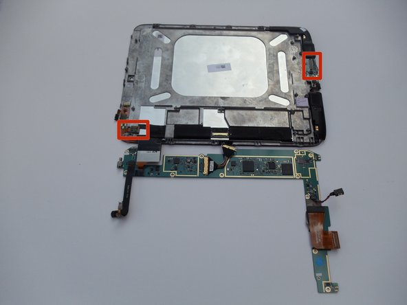

– Gently lift the L-shaped board—it’s like opening a treasure chest, but with fewer pirates.
– As you pull up, the top and bottom connection points will pop free. No magic tricks here, just good ol’ physics!
Step 7

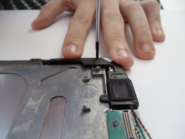
– Let’s get started by removing the seven 2 mm black screws that hold the speakers in place. Grab your trusty Phillips #00 screwdriver and get to work!
Tools Used
Step 8

– Gently lift the disconnected speakers out of their cozy little spot—like giving them a VIP pass out of their seat.
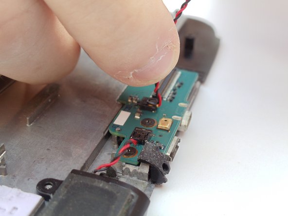
– Pinch the red and black cable between your index finger and thumb, like you’re about to make the world’s tiniest rock-paper-scissors move.
Step 9

– Gently lift the connector to set the speakers free. No need for a tug-of-war—just a smooth lift and you’re golden!
Step 10

– Let’s get started by removing the two 2 mm screws at the top of the panel. Grab your trusty Phillips #00 screwdriver and get to work!
Tools Used
Step 11


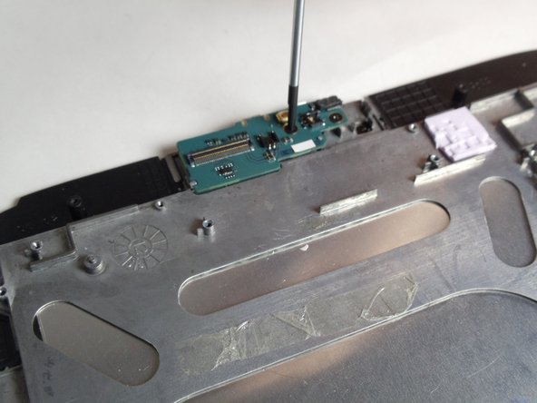
– Grab your trusty Torx T4 screwdriver and carefully remove the single 2 mm screw on the front of the panel. Nice and easy!
Step 12

– Putting your device back together is a breeze! Simply work backward through these steps: start by placing the panel snugly into position, then secure it with each screw. Kick off with the 2mm Torx T-4 screw, followed by the two 2mm PH00 screws as shown in the instructions.
–
Success!