Lenovo Yoga Tablet 10 Screen and Frame Assembly Replacement
Duration: 45 minutes
Steps: 31 Steps
Before diving into this guide, it’s a good idea to brush up on your soldering skills. If you’re looking for a little help with that, check out some tips on soldering!
Step 1

The screws you’re looking for are tucked away behind the stand on your device. Just a little hidden treasure!
Our model was missing these screws entirely, so we didn’t have to worry about them.
– Unscrew those two Phillips #000 screws and set them aside. You’re doing great!
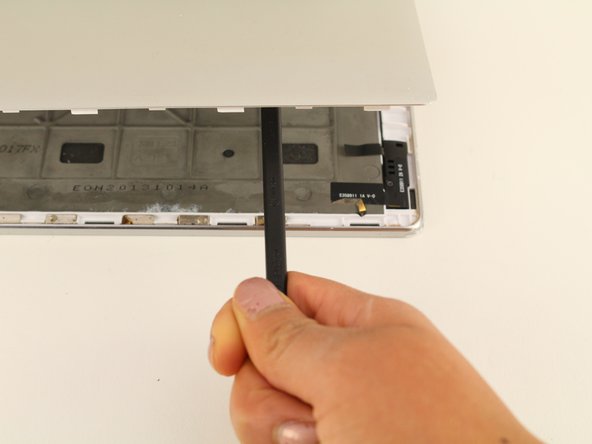
Step 2

Before you start tearing things apart, make sure to check out Step three first. If you don’t, you might end up snapping the back cover, and that’s no fun. Let’s do this right and avoid any potential damage.
– Grab a plastic opening tool and work your magic—slide it between the edge of the back cover and the screen, gently prying those stubborn edges loose. Take your time, finesse is key!
Tools Used

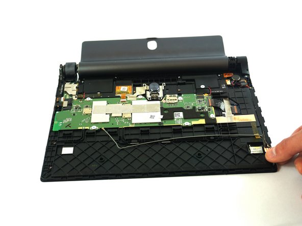
Step 3

– Grab your spudger and gently work your way into the center of the device. Apply a little upward pressure to pop off the back case. It should come off without too much trouble, but be careful not to rush it!
Tools Used

Step 4


– Let’s get started by removing one 5mm screw using your trusty Phillips #00 Screwdriver. This is the first step in getting your device back up and running, and we’re excited to have you on board!
Tools Used

Step 5


– Grab your trusty spudger and gently wedge it between the camera and battery connectors and the circuit board. Give it a little upward nudge to pop those connectors free.
Tools Used
Step 6

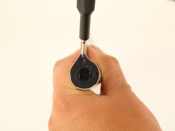
– Grab your Phillips #00 screwdriver and take out that single 5mm screw.
Tools Used
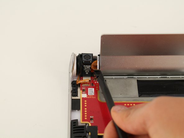
Step 7


– Grab your trusty nylon-tip tweezers and gently nudge the camera free from its cozy spot between the power button and the kickstand. Take it slow—no need to rush greatness!
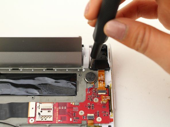
Step 8


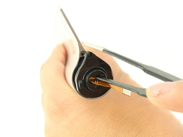
– Grab your trusty tweezers and carefully pinch the headphone jack cover. Give it a confident pull straight up and away from the device—like you’re lifting the lid on a mystery! No twisting or wiggling needed, just a clean lift.
Step 9


– Let’s get started by removing the two 3.5mm screws. Grab your trusty Phillips #00 Screwdriver and get to work – it’s time to take your device apart and fix it up.
Tools Used
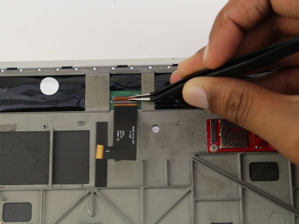
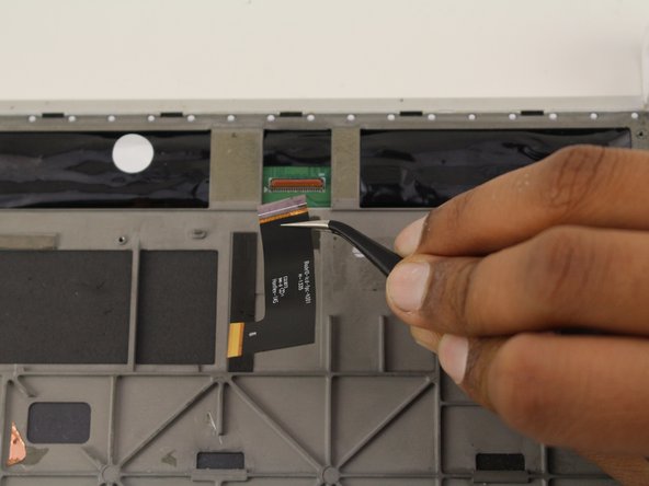
Step 10


– Carefully slide the spudger between the headphone jack and the motherboard, then gently push upwards to detach them.
– Now, just pull the wire towards the headphone jack to fully disconnect it.
Tools Used
Step 11


– Grab your tweezers and gently lift the headphone jack up and towards you—give it a smooth pull, no wrestling moves needed!
Step 12


Watch out! Using too much oomph with that metal spudger might just pop the plastic cover. If you sense it’s about to snap, try switching up the angle of your spudger action.
Stick to using that metal spudger on the side with the headphone jack, folks! Trying it on the other side? Well, that’s like trying to find a rainbow without a pot of gold—no luck there!
– Grab your trusty metal spudger and gently slide it between the kickstand and the plastic. A little upward pressure on the spudger will help you nudge the battery compartment lock out of place. Nice and easy, you’ll get it in no time!
Tools Used

Step 13


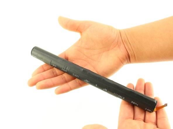
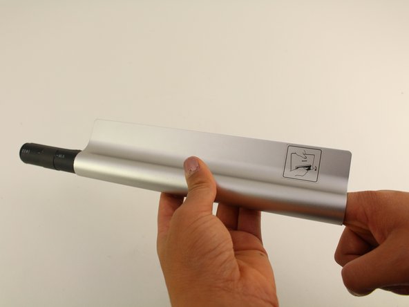
The battery compartment also doubles as the kickstand. Pretty clever, right?
– Time to get started! Gently pull the battery compartment away from the device.
Step 14

– Use tweezers to carefully remove the gray tape and reveal a screw at each end of the compartment. Take your time and be gentle to avoid damaging any of the surrounding components.
Step 15

– Using your trusty Phillips #00 screwdriver, unscrew one 3.5 mm screw from each end. You’ve got this!
Tools Used
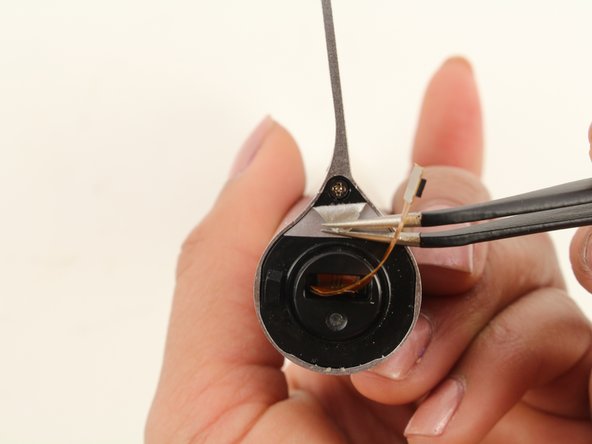
Step 16

When you slide the tweezers into the center of the cap and lift up, you should hear a good, solid snap—music to your DIY ears!
– Grab your trusty tweezers and gently pop off the cap from the side where the orange connector is peeking out. You’ve got this!
Step 17

Whatever you do, don’t let that cap wander off—it’s got places to be, and losing it will just make your life harder later.
– Give that battery a gentle nudge with your hands, pushing it towards the far side of the compartment. You’ve got this!
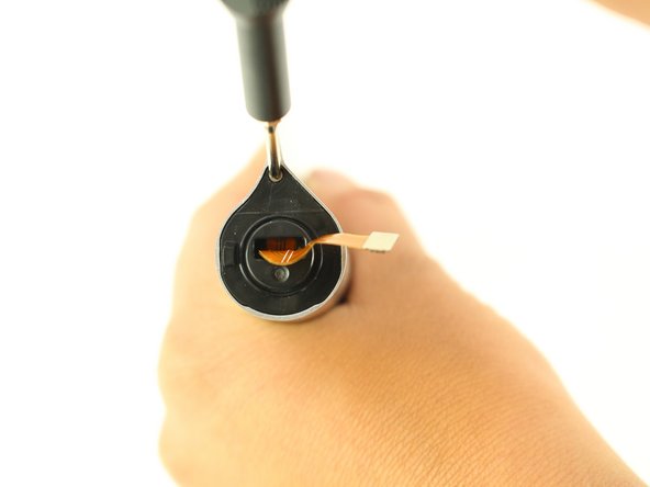
Step 18

– Grab your trusty Phillips #00 screwdriver and take out those four tiny 1 mm screws like a pro!
Tools Used
Step 19
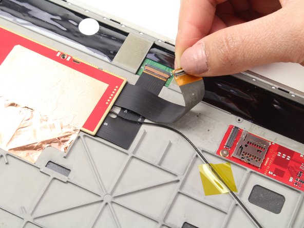

– Grab your trusty spudger and gently pop that ribbon wire loose with an upward nudge. Easy does it, champ!
Tools Used
Step 20
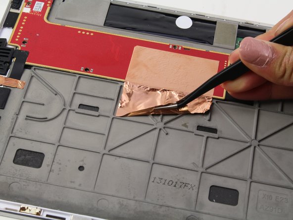
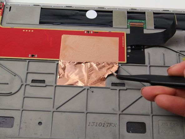
Be careful, the foil might get a little unruly!
– Grab those tweezers and gently lift the foil up. You’ve got this!
Step 21
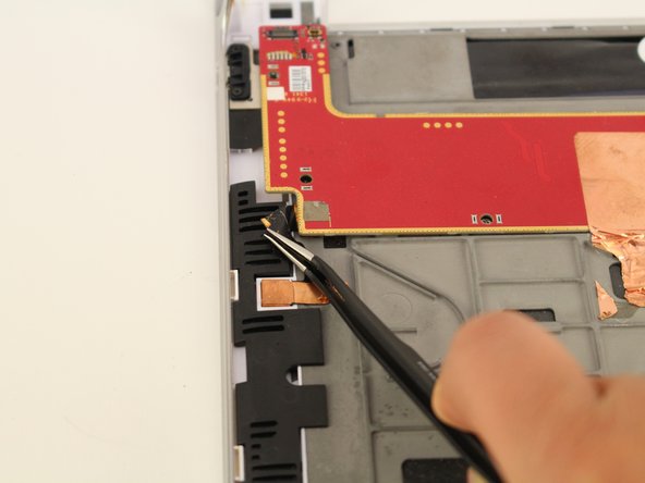

– Grab those tweezers and gently peel back the black tape from the corner of the printed circuit board. You’ve got this!
Step 22

– Grab those tweezers and give the board a smooth 180-degree flip towards you. Easy, right? Just make sure you’re gentle with it.
Step 23

– Take hold of the wire on the PCB and gently tug it toward the edge of the headphone jack using tweezers—no stress, you’ve got this!
Step 24


– Let’s get started by removing the one 5mm screw using a trusty Phillips #00 Screwdriver. Take your time and make sure it’s out completely.
Tools Used
Step 25

– Time to get a little gentle yet firm – use your trusty tweezers to carefully pry up the tape and disconnect the module by pulling it upwards. Take your time, you got this!
Step 26

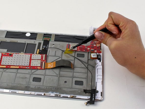
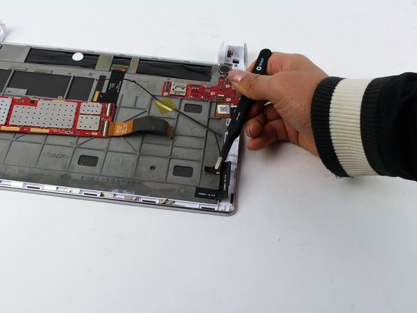
– Gently grab the yellow piece of tape with your tweezers and peel it off by pulling it upwards. Nice and easy, you got this!
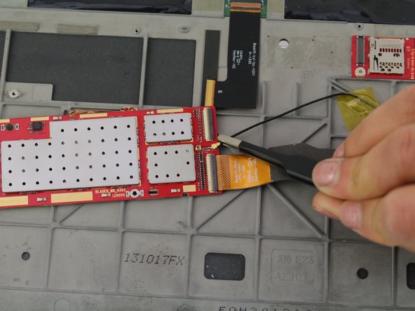
Step 27

– Grab your trusty tweezers and gently lift the ribbon wire—think of it as untangling a tiny electronic spaghetti strand. Once free, disconnect it from the motherboard with care.
Step 28

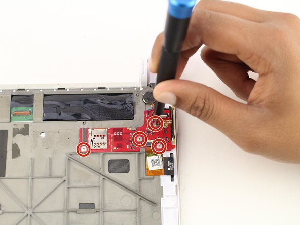
– Grab your trusty screwdriver and remove the four tiny 1mm Phillips #00 screws. They’re small but mighty, so keep an eye on them!
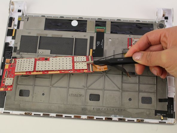
Step 29
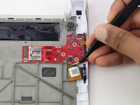

– Grab your tweezers and gently pull the wire away from the PCB. Nice and easy, no need to rush!
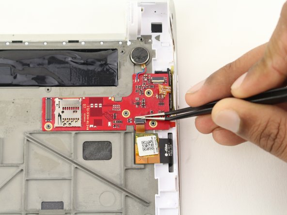
Step 30

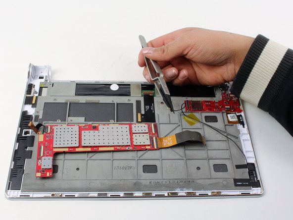
– Gently desolder the wire, making sure to handle it with care.
– Next, carefully remove the PCB and the round vibration module.
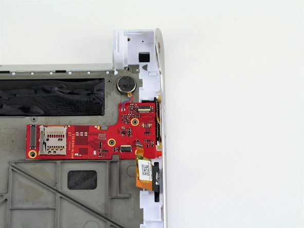
Step 31
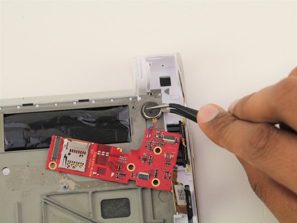

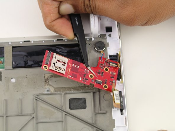
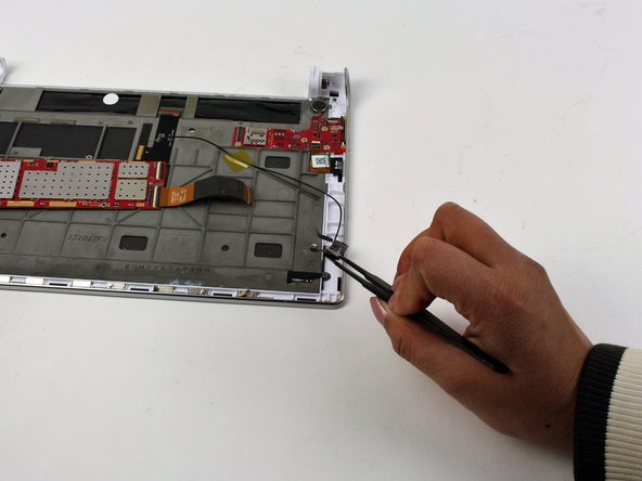
Watch out! Those precision tweezers are sharp, and we wouldn’t want them to go slicing through your PCB or vibration module. Stay safe while you work!
– Grab your precision tweezers and gently lift the PCB along with the round vibration module from the bottom corner, carefully pulling it upward. Take your time, and remember, you’re doing great!
Success!