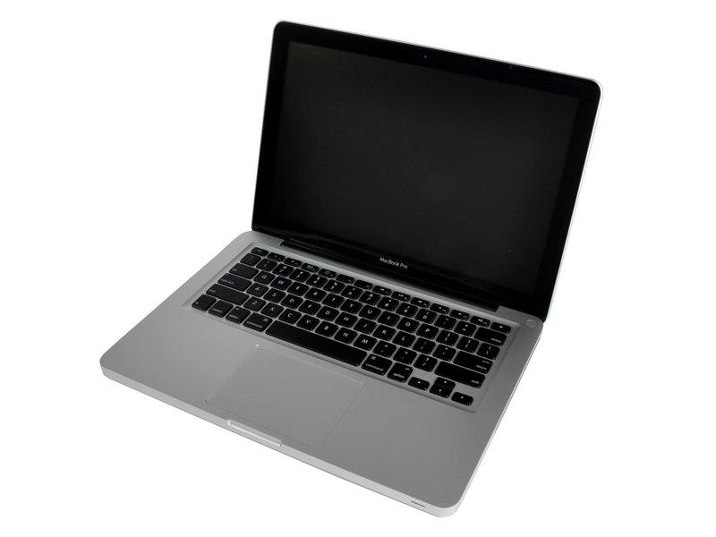
MacBook Pro 13″ Unibody Mid 2010 Keyboard Replacement
Duration: 45 minutes
Steps: 29 Steps
Hey there! Just a quick heads up: if you find yourself feeling a bit lost or need a hand with your repair, don’t hesitate to reach out. You can always schedule a repair and get back on track in no time!
Ready to give your MacBook Pro a little keyboard makeover? This guide is all about swapping out that keyboard without messing with the entire top case. Just a heads up: you’ll need to take apart almost every component of your MacBook Pro to get to it. So, buckle up and follow along with steps 1 – 36 from the MacBook Pro 13″ Unibody Mid 2012 Upper Case Replacement guide. And don’t forget, if your new keyboard didn’t come with a backlight, make sure to transfer your old one over. If you need help, you can always schedule a repair.
Step 1

– Unscrew those 10 pesky screws holding the lower case of your MacBook Pro 13″ Unibody in place!
Step 2

– Gently lift the lower case and nudge it toward the back of the device to release those pesky mounting tabs.
Step 3


Check out the fan socket and connector in the second and third pictures! Just a heads up: when you’re using your spudger to gently lift the fan connector straight out of its socket, be super careful not to snap off that plastic fan socket from the logic board. The layout in the second picture might look a bit different from your device, but don’t worry—the fan socket is the same!
A little twist of the spudger from below those fan cable wires can do wonders to pop that connector loose. You’re almost there!
– Grab your trusty spudger and gently wiggle it to lift the fan connector right out of its cozy home on the logic board.

Step 4

– Let’s get those screws out! Start by removing the following three screws:
Step 5

– Gently lift the fan out of the upper case like you’re unveiling a surprise gift!
Step 6


– Take hold of the plastic pull tab that’s keeping the display data cable lock secure and give it a twist toward the DC-In side of your computer.
– Carefully slide the display data cable connector away, keeping it parallel to the board. You’ve got this!
Step 7


– Unscrew those two little screws holding the display data cable bracket snugly to the upper case. You’ve got this!
– Gently lift the display data cable bracket out of its cozy spot in the upper case. Easy peasy!
Step 8

– Gently wiggle the flat end of your spudger to lift the subwoofer and right speaker connector off the logic board. You’ve got this!
Tools Used
Step 9

This socket is made of metal and can bend pretty easily, so handle it with care! Make sure to line up the connector with its socket on the logic board before you bring them together.
– Gently tug the camera cable connector towards the optical drive to unplug it from the logic board. You’ve got this!
Step 10


– Gently use the flat end of a spudger to lift the optical drive, hard drive, and trackpad cable connectors off the logic board. You’ve got this!
Tools Used


Step 12

– Carefully remove the little strip of black tape from the keyboard backlight ribbon cable socket. Just peel it away like you’re unwrapping a surprise gift!


Step 14

– Grab your trusty spudger and gently nudge the battery indicator cable connector up from the logic board. You’ve got this!
Tools Used
Step 15

– Grab the tip of your trusty spudger and gently wiggle it to loosen that microphone from the sticky adhesive keeping it snug against the upper case. You’ve got this!
Tools Used
Step 16

– Unscrew these little guys:
Step 17


While it’s not a must to remove the battery before tackling the logic board, doing so can really help make the process smoother and safer. If you choose to keep the battery in, just remember to handle the logic board with care and avoid bending it against the battery case near the bar code. You’ve got this!
– Unscrew those Tri-point screws holding the battery in place on the upper case. You’ve got this!
– Gently lift the battery out of its cozy spot in the upper case. Easy peasy!
Step 18


– Gently lift the logic board by its left edge and raise it just enough for those ports to clear the upper case side. You’re doing great!
– Now, carefully pull the logic board away from the upper case. Just keep an eye out for the DC-In board; it might try to tag along!
Step 19

Just a friendly reminder: it’s a good idea to unplug the subwoofer connector from the logic board to keep any pesky electrical discharges at bay. No pressure, though! This step is totally optional.
– Gently peel away any soft padding that might be covering the connector, and with a little finesse, lift it straight out of its cozy socket on the logic board.
Step 20

Before you dive into disconnecting the camera cable, gently slide the little clear plastic cable retainer (highlighted in red) that’s glued to the logic board out of the way. Just a heads-up: be super careful not to knock off any components while you’re maneuvering it away from the camera cable connector. You’ve got this!
This socket is made of metal and has a tendency to be a bit bendy. So, take a moment to align the connector with its socket on the logic board before bringing the two together. You’ve got this!
– Gently pull the camera cable connector towards the optical drive to free it from the logic board. You’ve got this!
Step 21

– Gently coax the optical drive connector upward from the logic board using the flat end of a spudger. You’ve got this!
Tools Used
Step 22

– Gently use the flat end of a spudger to lift the hard drive connector straight up from the logic board. You’ve got this!
Tools Used
Step 23

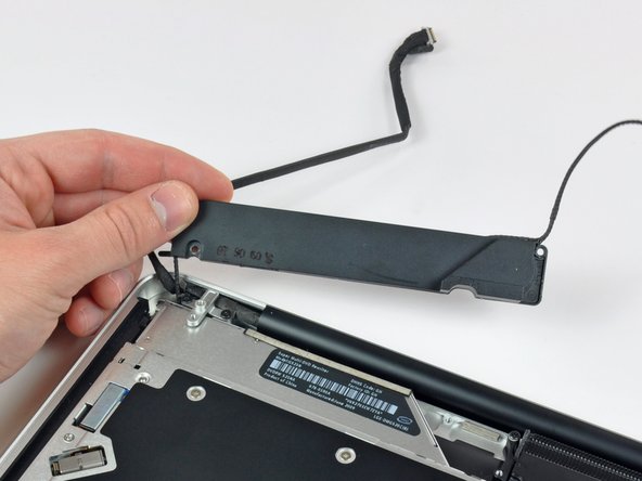
– Unscrew the screws holding the subwoofer snugly in place on the upper case. Let’s get this party started!
Step 24

– Hold on there! The subwoofer is still hanging out with the right speaker, so let’s not ditch it just yet.
– Gently lift the subwoofer off the optical drive and place it comfortably above the computer. You’re doing great!
Step 25


The leftmost screw might just want to hang out with the camera cable. Don’t worry, it’s not lost; it’s just being a little clingy!
– Unscrew the two 10 mm Phillips screws holding the camera cable bracket in place on the upper case.
– Gently lift the camera cable bracket out of the upper case, making sure to handle it with care.
Step 26


– First things first, take your trusty Phillips screwdriver and remove those three 2.5 mm screws that are holding the optical drive snugly in place on the upper case.
– Now, gently lift the optical drive from its right edge and slide it out of the computer like a pro!
Step 27
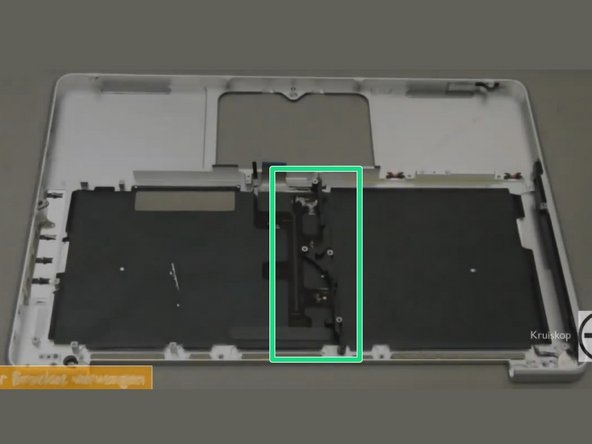

Give that top case a little spin until it matches the one in the picture! You’ve got this!
While the images are pulled from a YouTube video, they do a great job of showing you the right screws and parts to tackle.
– Let’s kick things off by unscrewing that 10mm Phillips #00 screw. You’ve got this!
– Next up, grab your trusty tool and remove the 5mm Phillips #00 screw. Easy peasy!
– Now, carefully take out the center bracket and set it aside. We’re making progress!
Step 28


– Time to shine – carefully pry the black keyboard backlight from the upper case and set it aside.
– Now it’s time to get under the surface: slide a spudger under the bottom right corner and work your way up the right side of the backlight.
– You’re almost there! Once the right side is loose, you can use your fingers to gently peel the backlight away from the keyboard. If you need help, you can always schedule a repair
Tools Used
Step 29

– Unscrew those pesky screws you’re facing!
– Carefully lift out the keyboard along with the power button—you’re doing great!
