Microsoft Surface Laptop 3 Motherboard Replacement Guide
Duration: 45 minutes
Steps: 41 Steps
Ready to swap out the motherboard on your Microsoft Surface Laptop 3 (13.5″)? This guide has your back! Some photos might feature a slightly different model, but no worries—any visual differences won’t throw off your repair groove.
Step 1


– Turn your laptop upside down and set it on your work surface with the feet pointing up.
Step 2


To get those little feet off the bottom of your laptop, grab your trusty spudger and use the pointed end. It’s like a mini ninja for tech repairs!
Just a heads up: the two feet at the back by the screen are a different breed from the two in the front. They’re like siblings with their own unique styles!
– Here’s a helpful tip to get you started: each foot has a sneaky little indent that makes removal a whole lot easier.
– To ensure your spudger is in the right spot, insert it at the nearest long edge and push it in parallel to the short edges of your laptop – just like the picture shows. Easy peasy!
Tools Used

Step 3


The two rear feet are stuck down with a bit of mild adhesive, but don’t worry, it’s easy to remove!
– Slide the pointy end of a spudger under one of the rear feet from the back edge.
– Wiggle the spudger under the foot and lift it up to pop it off.
– Rinse and repeat to take off the other rear foot.
Tools Used
Step 4


The front feet up front are held snug by plastic clips and a touch of light adhesive—nothing too wild, but they need a gentle nudge to come loose!
– Slide the sharp end of your trusty spudger under one of the two front feet, right at the front edge.
– Gently nudge the spudger beneath the foot and lift up to free it.
– Now, go ahead and do the same to the second front foot!
Tools Used
Step 5


– As you put things back together:
– Keep in mind that the front and rear feet are not the same. They have their own unique roles!
– The front feet are a bit picky – they only snap in one direction, so make sure they’re aligned properly before clipping them in.
Step 6


– Skip the hassle of sticking old, worn-out feet back on your device—try using 8 mm rubber furniture pads instead. They’re a slick solution that’ll keep your device steady.
– Just peel a pad from its backing, line it up with the foot cavity, and press it firmly in place. Simple as that!
Step 7

As you dive into this repair adventure, make sure to keep an eye on those screws! Each one has its own special spot, so return them to their original homes to keep your laptop safe and sound.
– Grab your trusty T5 Torx driver and pop out the four 3 mm screws hiding in the foot cavities—they’re holding the upper case to the device. Handle them like a pro, but don’t go all Hulk-mode during reassembly! These screws are delicate and strip faster than a bad karaoke performance.
Step 8


– Turn your device upside down, it’s time for a flip!
– Gently push the display open as far as it will comfortably go.
Step 9


Hold up! Don’t fully detach the upper case just yet—it’s still hooked up to the rest of the laptop.
Make sure the upper case sits snug all around. Any gaps between the upper and lower case near the screen could damage the display when it closes.
The top cover is held snugly in place with magnets.
– Grab the top edge of the upper case right above the keyboard and gently lift it straight up to set it free.
– Carefully raise the front edge of the upper case and pull it away from the laptop, being mindful not to put too much strain on the keyboard and touchpad ribbon cable hanging out below.
– When it’s time to put everything back together, lower the upper case onto the lower case until those magnets click into place and it sits nice and flat.
Step 10


The keyboard and touchpad ribbon cable is held down by a nifty magnet connector—pretty cool, right?
Some models might have this connector wrapped up in black tape, so keep an eye out for that!
– Gently slide the flat end of a spudger under one side of the ribbon cable connector and give it a little nudge to pop it loose.
– Carefully detach the ribbon cable from the motherboard.
Tools Used
Step 11


Make sure that ribbon cable is lying flat and relaxed – no twists or stress allowed!
– Gently take off the upper case.
– Place the upper case on a clean surface with the keyboard facing down.
Step 12

Taking out the SSD is like giving your battery a little vacation, and it’s the first thing you want to do before diving into any major repairs. Trust us, your device will thank you for it!
– Remove the 2.7mm screw that’s holding the SSD in place using a T5 Torx driver – easy peasy!
Step 13


Once you’ve taken out the SSD screw, watch as the SSD gracefully lifts up at a slight angle, ready for its next adventure!
– Hold onto the end of the SSD with a steady grip and slide it out from its board connector—nice and smooth like you’re unplugging a cord.
– When putting it back together, angle the SSD just right to pop it into its board connector, then lay it flat and secure it snugly in place with the SSD screw. Easy-peasy!
Step 14


– Grab a trusty pair of tweezers and gently peel away the two pieces of black tape that are snugly holding down the bottom left and bottom right corners of the motherboard. Easy peasy!
– When it’s time to put everything back together, feel free to reuse that tape if it’s still sticky enough to do the job!
Tools Used

Step 15


It might take a bit of muscle, but steer clear of bending the shield too much—you’ll want it to fit snugly when it’s time to put everything back together.
– Take a pair of sharp tweezers and gently slide one arm into one of the holes near the top-left corner of the heatsink shield—it’s like finding the sweet spot!
– Give it a confident upward tug to pop that top-left corner loose. Nice work, you’re on your way!
Tools Used
Step 16

– Go ahead and repeat the same procedure from the previous step to free up the top right corner of the heatsink shield.
Step 17
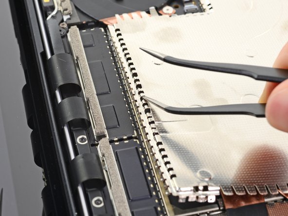
– Keep working your way along the top edge of the heatsink. Slide one of the tweezer arms into the shield holes and gently pry each one upwards as you go.
Step 18

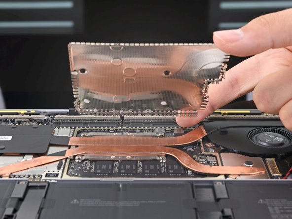

Handle the shield with care—bending it out of shape isn’t cool since you’ll need to pop it back in place later.
– Once the top edge is loose, grab the top of the shield with your fingers and gently pull it away from the heatsink. This will release the rest of the shield.
– Now, fully remove the heatsink shield.
Step 19

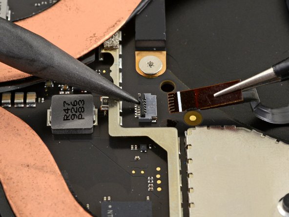
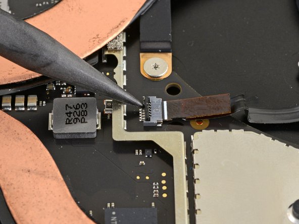
– Grab the sharp end of a spudger and gently nudge up that locking flap on the fan cable’s ZIF connector—think of it as giving it a little nudge of encouragement!
– Now, with a pair of tweezers, carefully slide the fan cable straight out of the connector. Take it slow and steady—you’re doing great!
Step 20

– Grab your trusty T3 Torx driver and let’s tackle those nine screws holding the heatsink in place:
– One little 2.5 mm screw
– Three cheerful 2.0 mm screws
– One sturdy 3.0 mm screw
– Two reliable 4.1 mm screws
– Two friendly 3.4 mm screws
Step 21

– During reassembly:
– Line up the heatsink with the centering peg on the motherboard—it’s like a perfect puzzle piece waiting to be placed.
– Secure the CPU tension screws in a crisscross ‘X’ pattern to keep things snug and balanced.
Step 22


– Gently use your finger to lift the far-right edge of the heatsink off that little alignment peg near the fan on the lower case. No need to rush—take it easy and keep it steady!
– Once you’ve cleared the peg, smoothly guide the right edge of the heatsink towards the front of the device. You’re doing great—keep it up!
Step 23


Don’t yank on the heatsink too much; those heat pipes can crease like paper.
If the heatsink seems a bit glued to the CPU, give it a gentle wiggle from side to side to help it break free from the thermal paste that’s keeping it snug.
– Pop off that heatsink with a little finesse!
Tools Used

Step 24


– Before you get that heatsink back in action, take a moment to follow this guide to give both the heatsink and CPU a good cleaning and to reapply some fresh thermal paste. You’ve got this!
Tools Used
Step 25

A few of the motherboard screws are hiding out under two metal shields that you’ll need to take off.
Handle those shields gently—they’ve got to go back on during reassembly!
– Grab your trusty opening tool and gently wedge it under one edge of the metal shield hugging the right side of the motherboard.
– Slide your way around the shield’s edges, popping it up here and there as you go, until it’s free and ready to lift off.
– Carefully lift and remove the shield.
Step 26


– Do it again! Remove that second shield from the left side of the motherboard, right next to the CPU.
Step 27
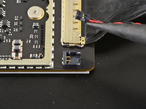
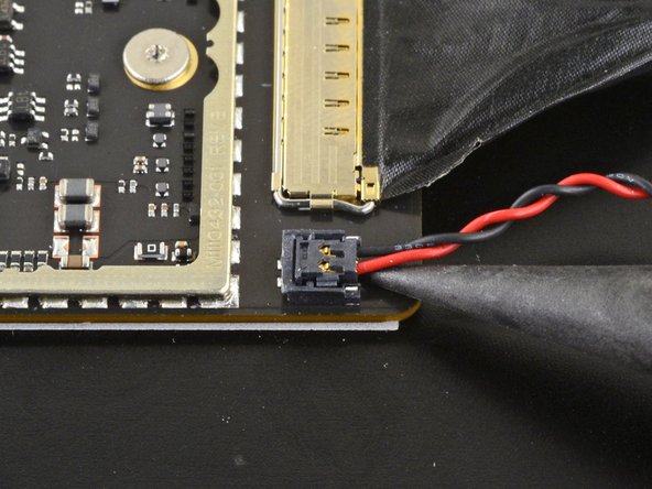

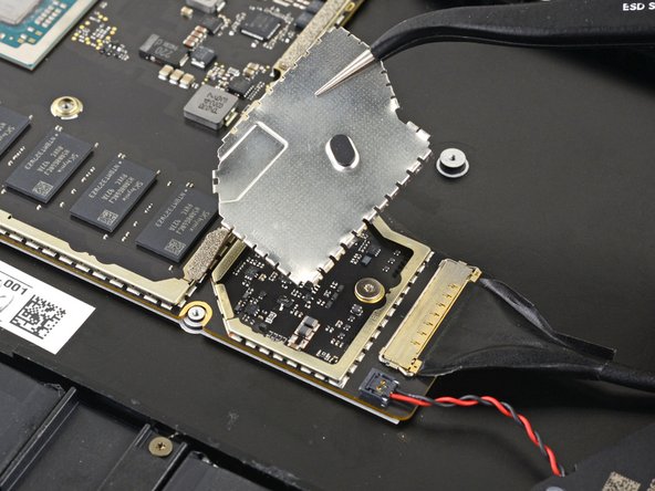
– Grab a spudger and gently lift that right speaker wire off the motherboard connector.
Tools Used
Step 28


– Grab an opening tool and carefully flip up the golden locking arm on the motherboard connector for the Surface Connect port—easy does it!
Step 29


– Grab that Surface Connect port cable and give it a gentle tug to disconnect it from its connector. You’ve got this!
Step 30


– Gently use the pointed end of a spudger to carefully lift and disconnect the left speaker wire from its cozy spot on the motherboard. You’ve got this!
Tools Used
Step 31


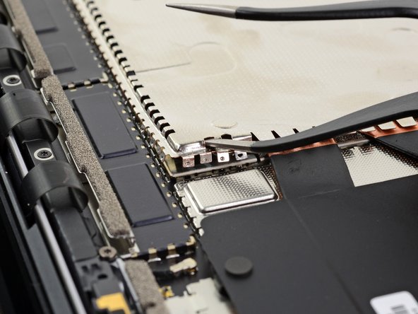
Be gentle with the shield—it’s going to need to go back on during reassembly, so let’s keep it in shape!
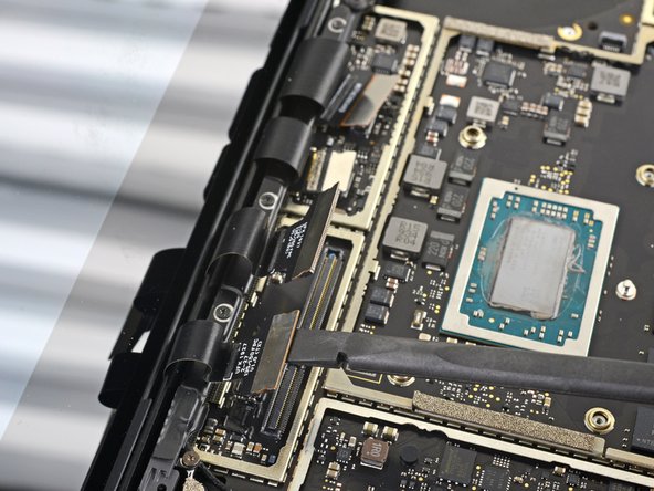
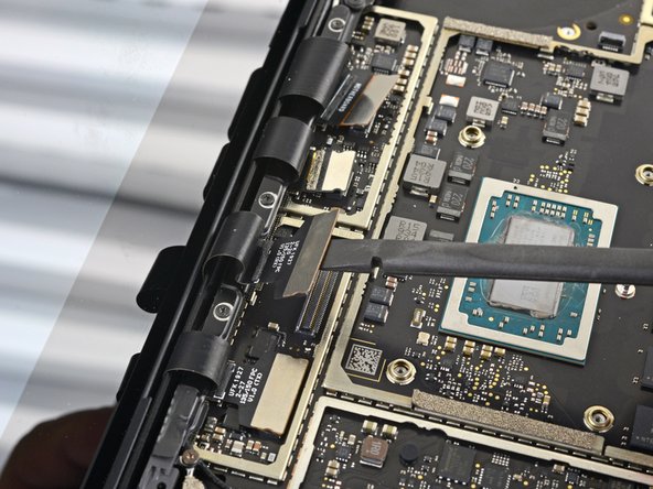
– Grab your trusty opening tool and gently coax up that black shield that’s guarding the right bank of display connectors.
– Work your magic by repeating this at various spots around the shield until it starts to loosen up.
– Once it’s feeling loose, go ahead and lift off the shield!
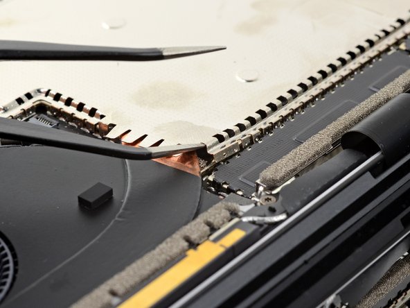
Step 32


– Go ahead and repeat that last move to take off the rest of the shield from the left side of those display connectors. You’ve got this!
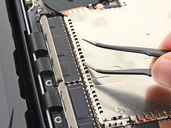
Step 33


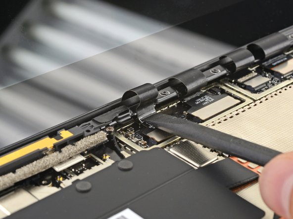
– Grab that trusty flat end of your spudger and gently lift the first display cable from its socket on the motherboard to disconnect it. You’ve got this!
Tools Used
Step 34

– Unplug the three remaining display connectors. Easy peasy!
Step 35

– When putting everything back together, grab the flat end of your trusty spudger and gently nudge those display cables back into their cozy little nook in the lower case. Easy does it!
Tools Used
Step 36


– Grab your trusty tweezers and give that antenna cable a gentle hug near its base.
– Now, with a steady hand, pull straight up to free the cable. You’ve got this!
Tools Used
Step 37

– Grab your T3 Torx driver and unscrew those two 3 mm screws holding down the motherboard bracket. Let’s get that bracket out of there!
Step 38
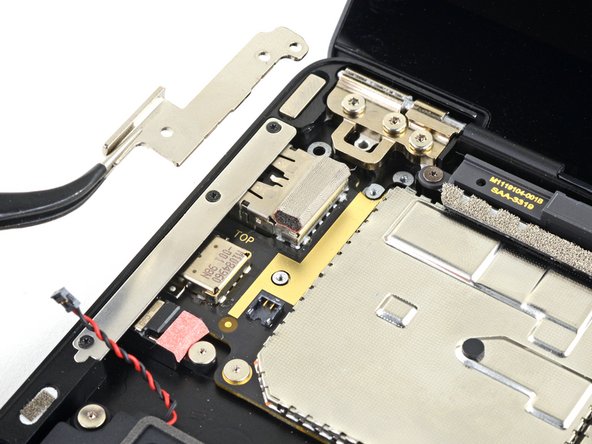

– Grab a trusty pair of tweezers and gently lift away the motherboard bracket with finesse.
Tools Used
Step 39


– Let’s get started! Use a T3 Torx driver to remove the six 2mm screws that hold the motherboard in place.
– To make things a bit easier, consider removing the three screws that secure the port bracket using a T3 Torx driver, then take out the bracket – it’s a nice little shortcut!
Step 40


Don’t let those sneaky screwpost braces under the motherboard vanish while you’re taking it out—keep an eye on them!
If the motherboard seems like it’s glued in place, give it a gentle nudge to the right to free up those I/O ports from their chassis cutouts.
– Gently use your fingers to lift up and pop out the motherboard—careful, it’s like removing a treasure from its chest!
Step 41

– Take a moment to compare your shiny new replacement part with the original—don’t forget to transfer any leftover components or peel off those pesky adhesive backings before you dive into the installation.
– To put your device back together, just retrace your steps in reverse. Easy peasy!
– Got some e-waste? Make sure to drop it off at an R2 or e-Stewards certified recycler. Let’s keep our planet happy!
– If things didn’t go quite as planned, don’t sweat it! Give some basic troubleshooting a shot or check out our Answers community for a helping hand.
– And remember, if you ever find yourself in a jam, you can always schedule a repair.
Success!

