Microsoft Surface Pro 5 Motherboard Replacement
Duration: 45 minutes
Steps: 54 Steps
Be extra careful—there’s a real chance you could accidentally damage the delicate, unprotected display while handling this step.
Follow this guide to swap out or replace the motherboard in your Microsoft Surface Pro 6. While you’re at it, a fresh dab of thermal paste on the CPU during reassembly could give your Surface a little performance boost. Make sure you’ve got some new thermal paste handy, as well as either high-concentration isopropyl alcohol or a thermal paste cleaner to prep the surface. Heads up: the display panel is quite fragile and unreinforced, so there’s a good chance it could get damaged during this process. Be generous with the heat application and take extra care when prying things apart.
Step 1

Before you dive into disassembly, make sure to shut down the Surface completely—like, power-down-for-a-nap completely.
You can use a hair dryer, heat gun, or hot plate to warm things up, but go easy on the heat—too much and the Surface might not like it. The screen and internal battery are sensitive to heat, so be careful!
Keep it chill and steady—you might need to reheat and reapply the iOpener a few times to get the Surface warmed up just right. Stick to the iOpener instructions, and you’ll avoid any overheating drama.
– Got a cracked screen? No worries—let’s keep those shards in check and your fingers intact! Slap on some clear packing tape over the entire screen, overlapping the strips until every piece of glass is locked down. Oh, and pop on those safety glasses to keep your eyes safe. Safety first!
– Warm up an iOpener and let it hang out on the right edge of the Surface’s screen for about two minutes. The heat will help loosen things up for the next steps.
Tools Used

Step 2


– Check out the layout of the screen adhesive before moving forward—it’s like a treasure map, so don’t skip this step!
– These zones are all about adhesive and perfectly safe to slice through.
– The display board and flex cables hang out pretty close to the edge here. Be super cautious and don’t slide the pick too far under the display—gentle moves only.
– Fragile antenna cables are chilling under this part of the screen. Stick to the plan carefully to avoid any damage. Oh, and the adhesive here? It’s the thickest, so brace yourself!
Step 3


Keep it chill—don’t push the opening pick deeper than the black bezel along the screen’s edge. Going too far could mess up the LCD, and nobody wants that!
– Gently slide an opening pick into the speaker opening on the screen and carefully work it under the glass. Be cautious not to push the pick into the speaker grille, as it’s delicate and can tear easily.
Step 4


– Swing that pick towards the bottom of the Surface and smoothly slide it under the lower edge of the speaker cutout.
Step 5


If your pick isn’t gliding easily, pause for a moment and give the area a bit more heat. Forcing it too hard could lead to cracked glass—and nobody wants that! Take your time and keep it cool.
– Gently slide the pick down the right edge of the Surface to break through the adhesive holding the screen in place.
– Keep the pick in the right edge to stop the adhesive from sealing back up.
Step 6

If you’re looking for a little extra heat, a hair dryer, heat gun, or hot plate can help get the job done. But remember—don’t go overboard! The screen and internal battery are sensitive to heat, so be cautious not to overheat your Surface.
You might find yourself needing to give the iOpener a little extra love by reheating and reapplying it a few times to get that Surface nice and toasty. Remember to check the iOpener instructions to keep things from getting too hot to handle!
– Warm up your iOpener and then let it do its magic on the bottom edge of the Surface’s screen for about two minutes. Easy does it!
Tools Used
Step 7


Keep the opening pick shallow—just till the black bezel on the screen’s side. Push it too far, and the LCD might end up crying for help.
– Take a new opening pick and carefully tuck it into the bottom right corner, then guide it around toward the bottom edge. Keep it smooth and steady!
– Now slide that pick along the bottom edge of your Surface—it’s like buttering toast but cooler—to break through the screen adhesive.
– Leave the pick chillin’ in the bottom edge to stop the adhesive from playing sticky tricks and resealing itself.
Step 8

A hair dryer, heat gun, or hot plate can lend some extra warmth, but don’t go overboard—the Surface’s screen and internal battery aren’t big fans of too much heat.
You might need to give the iOpener a few rounds of reheating and reapplying to get the Surface warmed up just right. Stick to the iOpener instructions to keep things safely under control—no overheating allowed!
– Warm up the iOpener again and place it on the left edge of the Surface’s screen for a solid two minutes to loosen things up.
Tools Used
Step 9


– Grab a new opening pick and slip it into the bottom left corner—then smoothly glide it around the bend toward the left edge.
– Work that pick along the left edge of the Surface to gently slice through the stubborn screen adhesive.
– Keep that pick nestled in the left edge to stop the adhesive from playing tricks and sealing itself back up.
Be extra careful when cutting along the left edge, especially the lower 2.5 inches (65 mm). Don’t push the opening pick in more than 1/8 inches (3 mm) here. The display cables are hanging out nearby, and they’re pretty easy to damage if you’re not careful. Once you’re past that area, just avoid pushing the pick too far past the bezel—keep it steady!
Step 10

You can use a hair dryer, heat gun, or hot plate for extra heat—just keep an eye on the Surface! Too much heat can mess up the screen or battery, and nobody wants that.
The adhesive is extra stubborn along this edge, so don’t be shy—reheat and reapply the iOpener as needed to get things toasty enough. Just stick to the iOpener instructions, and you’ll dodge any overheating drama!
– Warm up your iOpener and press it gently against the top edge of your Surface’s screen for about two minutes. It’ll help soften things up and make your life a lot easier when you go to work on the device.
Tools Used
Step 11


The next 6 inches (15 cm) along the top edge of your case are covered by the left and right antennas, snugly tucked between the case and the screen bezel. Be careful as you work through the next steps—these antennas are a bit delicate, and you don’t want to accidentally damage them!
– Glide your opening pick around the left corner like a pro, then slide it smoothly along the top edge of the Surface. Pause the action when your pick is chilling 2.75 inches (70 mm) away from the left edge.
Step 12


Keep that pick nice and parallel to the screen – you don’t want it catching on any antennas. Just gently work it in, no need to push it against the case.
– Gently slide the tip of your pick under the display where you last paused your cutting adventure. Just a friendly reminder: keep it shallow—no deeper than the bezel’s edge!
– Now, let’s roll! Carefully pivot the pick to the right, pressing its long edge into the screen adhesive hiding beneath the bezel. As you roll along, you’ll be slicing through that sticky stuff like a pro. Just remember, no sliding along the edge of the Surface—keep it classy!
– Keep the momentum going! Insert the tip of your pick right where you just made your cut and continue rolling to the right along the top edge of the Surface. Do this until your pick is 2.5 inches (64 mm) away from the right edge of the Surface. You’re doing great!
Step 13


– After you’ve cut through the adhesive over the antennas (8.5 inches or 22 cm from the left edge), glide that pick along the top edge like a pro, and smoothly round the top right corner to tackle any remaining adhesive. You’re doing great!
Step 14


Hold up—don’t yank that screen off just yet! It’s still tethered to the motherboard by a couple of cables.
– Gently pry up the screen assembly from the Surface case as if you’re handling a priceless treasure. If it seems stubborn, pause, and double-check that all the adhesive has been loosened—it doesn’t like surprises!
– Grab your trusty opening pick and glide it through any leftover adhesive like you’re slicing through butter. Smooth and steady wins the race!
– Watch out for the flash lens—it tends to wander off from the Surface case like it’s on vacation. Keep tabs on it, and make sure it finds its way back into its cutout during reassembly.
Step 15


– Carefully tilt the top of the screen assembly away from the case while sliding the bottom of the screen closer to the motherboard display connectors—like a smooth dance move!
– Gently rest the screen on the case with the connectors facing up. Be mindful not to crease those delicate display cables—they’re the real MVPs here!
Step 16


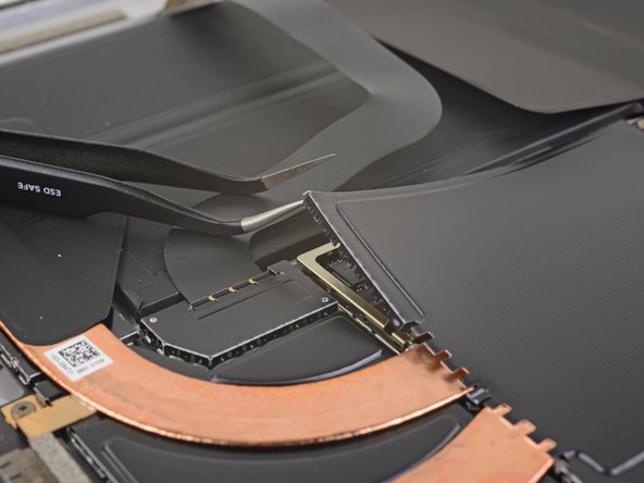
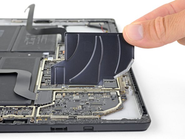
Keep the shield in shape—you’re gonna pop it back on later, so don’t go bending it like crazy!
– Grab your trusty opening pick and gently shimmy it under one edge of the EMI shield that’s hugging the display board—go slow and steady, no rush!
– Work your way around the shield, hitting different spots and prying carefully until it gives up and pops off.
Step 17

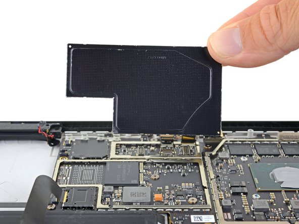
– Slide that EMI shield off the display board like a pro and set it aside. You’re doing great!
Step 18


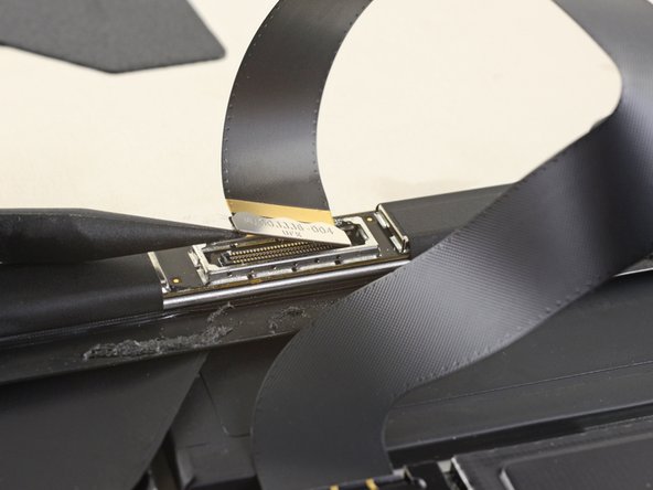
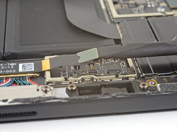
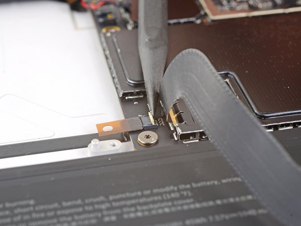
– Time to get that display cable out! Use the flat end of a spudger to carefully pry the display interconnect cable straight up and out of its socket on the board. Take your time, and it’ll be a breeze!
Tools Used

Step 19


Be gentle with that shield—you’re going to need it when it’s time to put everything back together!
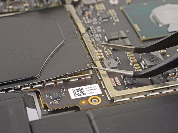
– Gently slide one point of your trusty pointed tweezers into a little gap on the edge of the EMI shield that’s cozying up to the digitizer connector.
– Now, give those tweezers a little wiggle to pry the EMI shield away from the display—just enough so you don’t bend it, okay?
– Keep going around the shield, repeating this lovely little dance until it’s free. Then, simply lift off the shield and celebrate your progress!
Tools Used

Step 20

– Now it’s time to carefully pull the rest of the shield away from the digitizer connector and completely remove it. You’re doing great!
Step 21

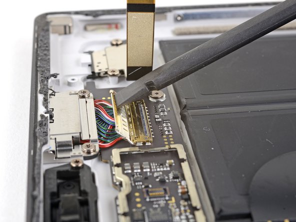
– Grab your spudger and, with a bit of finesse, pop the digitizer connector straight up out of its socket on the screen.
Tools Used
Step 22

– Carefully lift the screen assembly off the Surface. Take your time and keep it steady!
– When it’s time to put things back together, pause right here and check out this guide for a quick tip on swapping out the screen adhesive. It’s a small step that makes a big difference!
Step 23


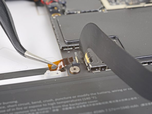
– Take the spudger—your trusty repair sidekick—and gently pop the microphone connector straight up from its socket on the motherboard.
Tools Used
Step 24

– Grab your trusty T5 Torx driver and let’s get those screws out! You’re removing the four screws holding the antenna support in place:
– Three screws measuring 4.5 mm—short and sweet.
– One screw that’s 6 mm—slightly longer but no sweat!
Step 25


– Grab your trusty spudger and gently pry up the antenna support from its little nook in the Surface—it’s like freeing a tiny piece of tech treasure!
– Pop that antenna support out of its spot and call it a day!
Tools Used
Step 26

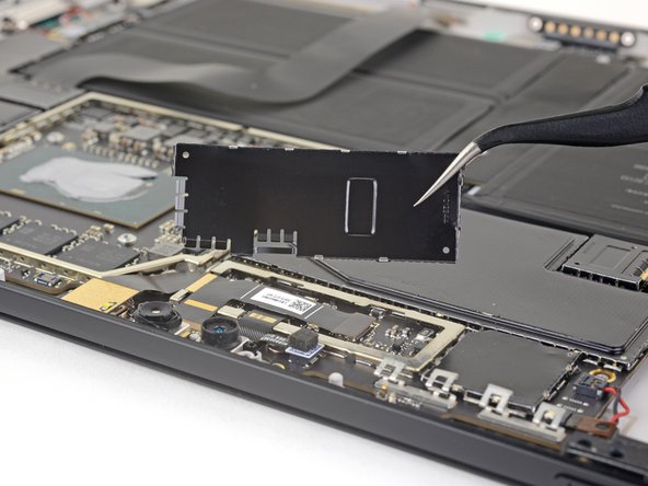
Be gentle with the shield—it’s going back in place when all’s said and done, so keep it looking sharp!
Watch out with those tweezers! They’re great tools but don’t let them poke holes in the battery while you’re working on that shield.
– Slide one point of a pair of pointed tweezers into the gap at the corner of the EMI shield covering the heat sink.
– Gently work the tweezers to lift the EMI shield away from the motherboard—take it slow and steady to avoid bending it. But don’t take it off just yet!
Tools Used
Step 27


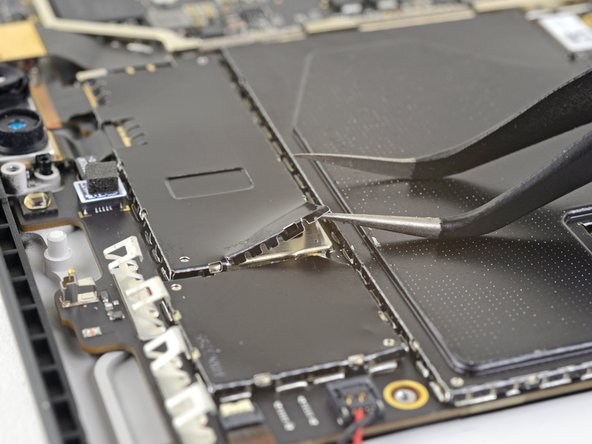
– Go ahead and repeat that last step for every corner of the EMI shield that’s snug around the heat sink. You’ve got this!
Step 28

– Take off the heat sink shield—it’s time to let your inner tech wizard shine!
Step 29

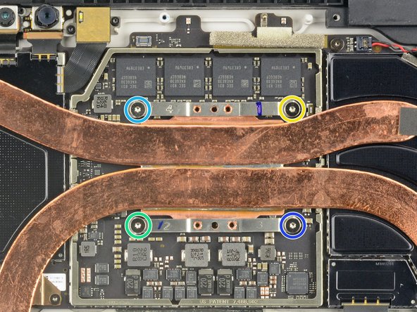
– Time to tackle the heat sink! First, pop out those ten Torx screws holding it in place:
– When you’re putting the heat sink back, give those screws a good criss-cross tightening—one turn at a time until they’re snug as a bug:
– Here’s the crew to look out for: Five 2.6 mm T3 screws and Four 3.3 mm T5 screws.
– Remember our trusty Screw Buddies? Let’s tighten them in this order: Screw 1, Screw 2, Screw 3, Screw 4.
Step 30


Be gentle and keep those heat sink pipes smooth and straight while removing—no dents, no creases, no worries!
– Grab the flat end of your trusty spudger and carefully nudge the heat sink straight up and off the CPU—easy does it, no need to rush!
– When it’s time to put things back together, don’t skimp on the cleaning. Give the heat sink and CPU a good cleanse, and be sure to spread some fresh thermal paste for that cool-factor these components deserve.
Tools Used
Step 31


– Grab your trusty spudger and gently pop the left speaker connector out of its socket on the motherboard—like a pro doing a secret handshake.
Tools Used
Step 32


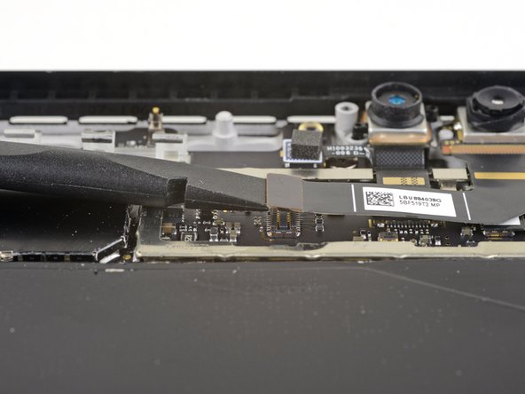
– Gently pop up the little locking flap on the ZIF connector with the pointy end of your spudger—think of it as opening a tiny treasure chest!
– Now, slide that volume and power button cable straight out of its spot on the motherboard like it’s gliding out of a secret escape route!
Tools Used
Step 33


– Take a spudger and gently nudge the right speaker connector up and out of its snug little spot on the motherboard.
Tools Used
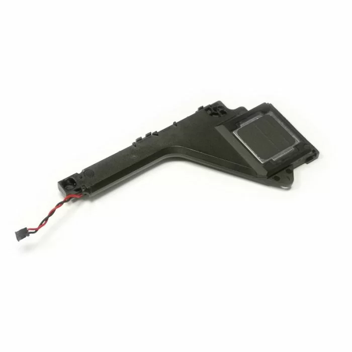
Step 34

– Grab your trusty T5 Torx driver and tackle the two screws holding down the right speaker:
– One 6 mm screw—easy peasy!
– One 3.7 mm screw—you’re on a roll!
Step 35


– Grab your trusty spudger and gently nudge up the left edge of the right speaker—just enough so it clears the neighboring components. Easy does it!
– Once you’ve got the left edge lifted, slide that speaker straight to the left and out of its comfy little case recess. Smooth moves!
Tools Used
Step 36

Be gentle with the shield! Try not to bend it too much, as you’ll need to put it back during reassembly. Handle with care!
– Pop a pointed tweezer tip into the gap on the corner of the EMI shield hanging out by the camera connectors.
– Give it a gentle pry with the tweezers—just a little at a time—to ease the EMI shield off the motherboard while keeping it unaffectively straight.
– Work your way all around the shield’s edges with the tweezers, taking your time until it pops free. Then, lift it off and you’re all set!
Tools Used
Step 37

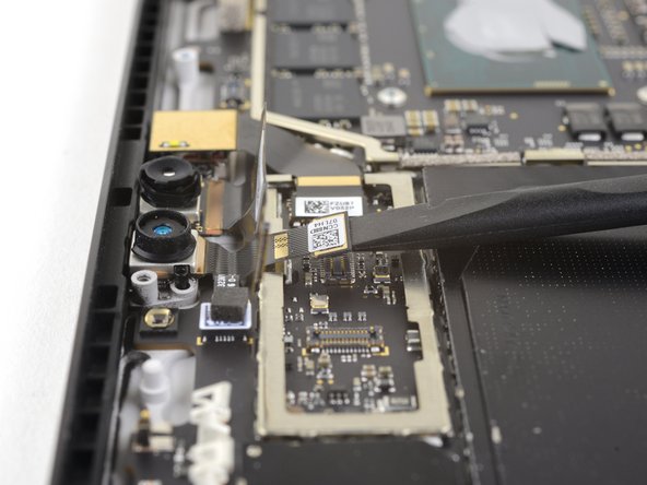
– Gently use the flat end of a spudger to pop the front-facing camera connector out of its socket on the motherboard. Take your time—precision is key here!
Tools Used
Step 38

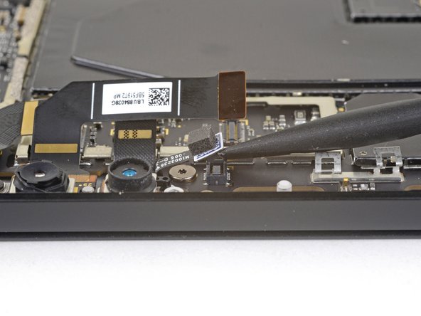
– Gently slide the flat end of a spudger under the face-detection camera connector and lift it out of its cozy home on the motherboard. Easy peasy!
Tools Used
Step 39


– Grab your trusty spudger and gently pop that rear-facing camera connector right out of its socket on the motherboard. Easy does it, you’re doing great!
Tools Used
Step 40

– Gently use the flat end of a spudger to lift the microphone connector out of its cozy spot on the motherboard. You’ve got this!
Tools Used
Step 41
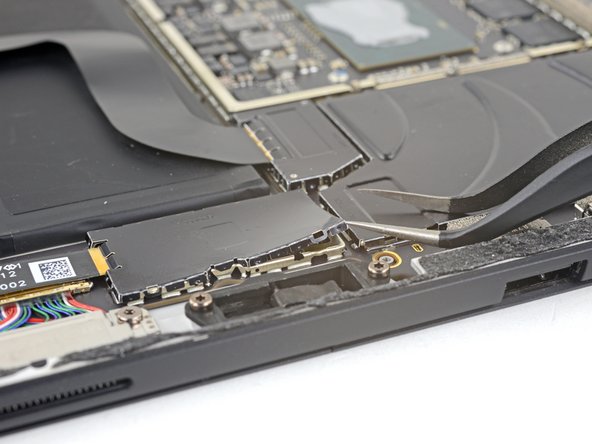

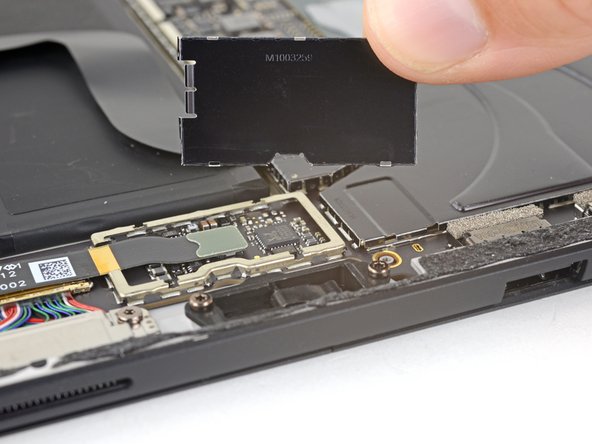
Be gentle with the shield—it doesn’t like to be bent too much, and you’ll need to put it back on during reassembly.
Watch out for the battery! Tweezers can be tricky, so keep them away from the battery while working on the shield.
– Take one tip of your trusty pointed tweezers and slide it into a gap in the corner of the EMI shield that’s covering the microSD card reader connector.
– Gently pry the EMI shield up and away from the motherboard. Be patient and careful—no need to bend it out of shape!
– Work your magic around the edges of the shield, repeating this maneuver at various points until it’s loose. Lift it off and set it aside like a pro.
Tools Used
Step 42

– Grab your spudger, flat end forward, and gently pop the microSD card reader connector up and out of its snug little spot on the motherboard. No rush—it’s all about finesse!
Tools Used
Step 43

– Time to get started! Use the flat end of a trusty spudger to carefully pry up the flap covering the Surface Connect port connector. Take your time, it’s an easy step!
Tools Used
Step 44

– Gently wiggle the SurfaceConnect port connector free from the motherboard socket—it’s like unplugging a tiny robot, so be patient and smooth.
Step 45

– Grab your trusty spudger and use its pointy end to gently lift that tiny locking flap holding the headphone jack cable ZIF connector in place.
– Now, with a smooth motion, slide the headphone jack cable straight out of its cozy home on the motherboard.
Tools Used
Step 46

Be gentle with the shield—it’s going back in place when all’s said and done, so keep it looking sharp!
Watch out with those tweezers! They’re great tools but don’t let them poke holes in the battery while you’re working on that shield.
– Grab those pointed tweezers and slide one tip into the gap at the corner of the left-most large EMI shield still hanging around.
– Gently wiggle the tweezers to pry the EMI shield off the motherboard, but keep it cool—no bending allowed!
– Work your way around the shield, repeating the prying motion at different points until it’s ready to part ways. Then, go ahead and remove it.
Tools Used
Step 47

– Now it’s time to tackle the other side – repeat the previous step to remove the remaining large EMI shield from the right side of the motherboard. You’re making great progress!
Step 48

– Bust out your trusty T3 Torx driver and unscrew those eight 2.5 mm bad boys holding down the motherboard. Let’s get it done!
Step 49
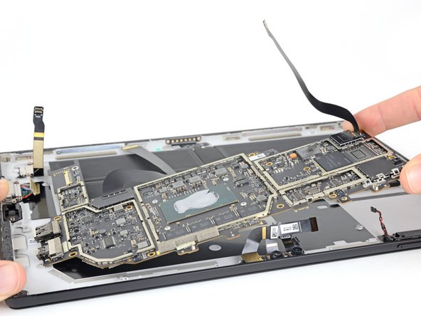

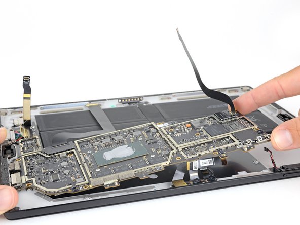
– Gently lift the non-port-side of the motherboard just enough to clear the surrounding components and the case edge—no heroic efforts needed here, just a little wiggle room!
– Slide the motherboard away from the ports, making sure the ports have completely vacated their snug slots in the case before you go for the full removal.
– Carefully remove the motherboard and give yourself a pat on the back—you’re doing awesome!
Step 50


Avoid bending the shield too much—it’s gotta go back in during reassembly, and we want it looking sharp!
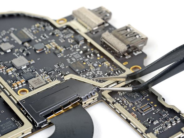
– Let’s get started! Carefully insert one point of a pair of pointed tweezers into a gap in the corner of the EMI shield covering the display interconnect connector. This is a delicate step, so take your time.
– Now, use the tweezers to gently pry the EMI shield away from the motherboard. Work your way around the shield, loosening it bit by bit, without bending it. You’re making great progress!
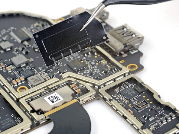
– Keep going! Repeat this process at different points around the shield until it’s completely free. Once it’s loose, you can remove the shield. You’re one step closer to a successfully repaired device!
Tools Used
Step 51

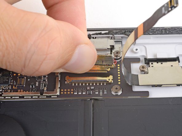
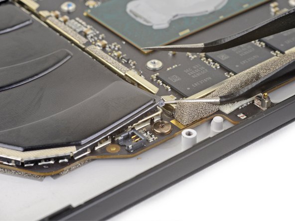
– Gently use the flat end of a spudger to lift the display interconnect cable straight out of its socket on the motherboard. Take your time and make sure it’s all the way out before moving on.
Tools Used
Step 52

Be gentle with the shield—it’s got a job to do when putting everything back together!
– Gently wiggle one tip of your trusty tweezers into a gap along the edge of the EMI shield that’s guarding the digitizer connector like a bouncer.
– With finesse, use the tweezers to nudge the EMI shield away from the display—push it as far as you can without warping it into a sad pretzel shape.
– Keep repeating this move around the shield’s edges, working your magic until it finally lets go. Voilà! Shield removed.
Tools Used
Step 53
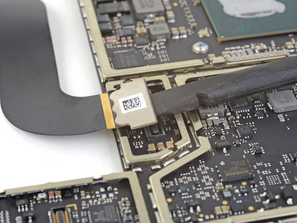

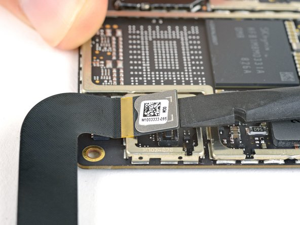
– Time to get that digitizer connector out! Use the flat end of a spudger to carefully pry it straight up and out of its socket on the motherboard. Take your time, and it’ll be a breeze!
Tools Used
Step 54

– Just the motherboard left to go!
Success!