Monroe KA Teardown
Duration: 45 minutes
Steps: 147 Steps
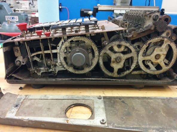
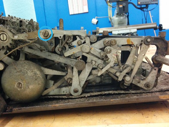
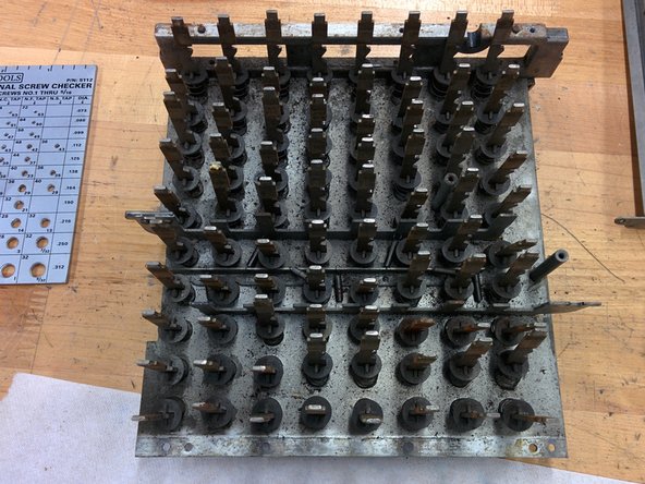
Ever stumbled on a funky machine at a yard sale that looks like a cash register and a typewriter had a wild night? That’s probably an electromechanical calculator—your granddad’s answer to crunching numbers before electronics took over. These old-school gadgets pop up on eBay all the time, but many of them are out of commission. Chances are, the last time anyone used it was back in the 1960s, so it’s probably full of crusty grease, dust, and maybe a few mystery twigs. Years of shuffling around and zero TLC also mean stuff might be misaligned or broken by curious hands. Manuals and repair guides? Pretty much unicorns. So, this guide is here to walk you through taking apart a Monroe KA calculator (the K series was made from 1921–1928, and the A stands for Automatic—motorized, baby!), so you can clean, fix, or replace what needs it. Along the way, you’ll get an inside look at the neat mechanisms that power these classics. This model could even multiply and divide manually by adding and subtracting over and over—old-school multitasking at its finest.
Step 1

Make sure to clear your workspace of any curious cats, small children, and capybaras. They’re great at finding tiny parts, and trust us, you’ll be dealing with a lot of them!
– Set up your workspace like a pro: lay down some clean white paper or a white mat board to keep things tidy. Brighten up the area more than you think you’ll need, and try to light from multiple angles to avoid shadows and see everything clearly.
– Gather a cardboard box and a bunch of press-to-close bags to keep your parts organized. Toss each pulled-off component into its own labeled bag—don’t be shy with the number of bags! Keeping parts sorted makes reassembly a breeze and helps prevent losing anything.
Tools Used
Step 2


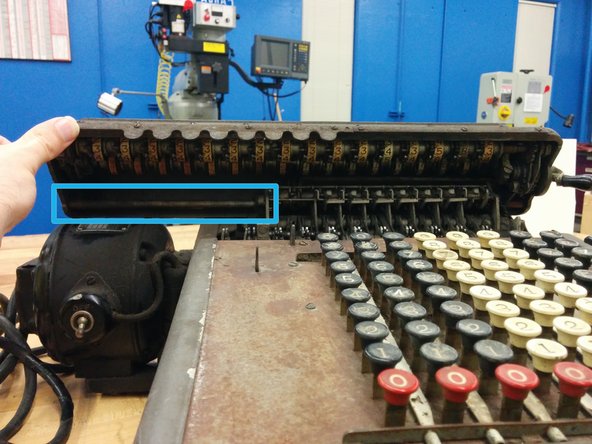
– First up, let’s carefully remove the carriage — that’s the top part with all those number wheels on it.
– Place the calculator with its keyboard facing you. This will set the left and right sides for the next steps.
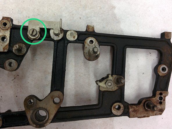
– Loosen the screw on the lower left side of the carriage, found on the left side.
– If that screw just keeps spinning, try inserting a screwdriver at the opposite end of the shaft, which is on the lower right side of the carriage. Don’t twist it just yet—only turn the left side screw.
Step 3

Back in the 1920s, screw threads were standardized just like they are now. The one you just unscrewed? That’s a #8-36!
All the screws here are machine screws with fine threads and slotted heads. Fun fact: Phillips head screws were still a twinkle in some inventor’s eye back then!
As for the heads of those 1920s screws, they were pretty much cylinders. Nowadays, we’d call that a pan-head screw.
Now, about the lengths—I’m not entirely convinced they had a standard. If they did, their precision leaves something to be desired. This one measures 0.298 inches long (the threaded length), which is about 19/64 inches. Not exactly standard sizes! When looking for a replacement, just grab the nearest length that fits.
– Toss that screw into a small bag right away to keep it safe!
– Label the bag as ‘bag number 1’ so we can track the serial number of the calculator later on.
– Give yourself a pat on the back—you’re now officially organized and ready to go!
Step 4

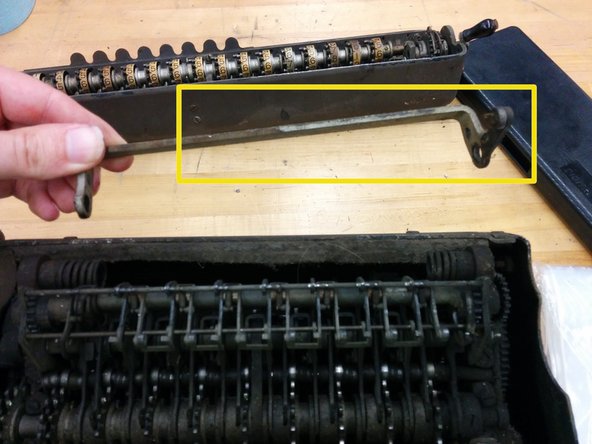
– Gently pull back on the carriage latches and give the carriage a little nudge upwards.
– This shaft runs the whole length of the carriage. Give it a little push to the right. You might need to wiggle the carriage a bit to help it out—it’s probably a little stubborn after all these years of air exposure.
– Now, lift the carriage completely off and set it aside.
– This other part will come off along with it, no sweat!
Step 5

– Check out the bottom side of the carriage along with the other components. Just a heads up, the shaft isn’t included in this view. Toss everything into a box to keep them from going MIA!
Step 6

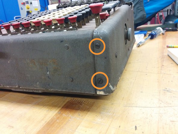
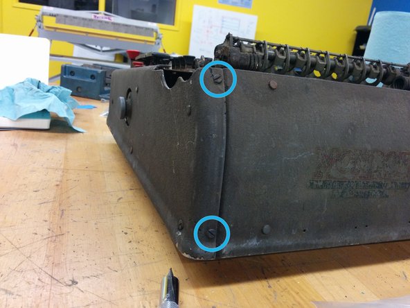
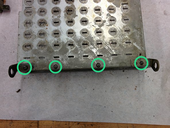
– Start by removing these two screws, which are #6-40 and approximately 3/8″ long. Next, flip to the back and take out these two screws, also #6-40 but about 1/4″ in length. Then, on the front side, unscrew these two #6-40 screws, each roughly 1/4″ long. Keep all these screws safe by bagging them in Bag #1. If you need a hand along the way, you can always schedule a repair.
Step 7

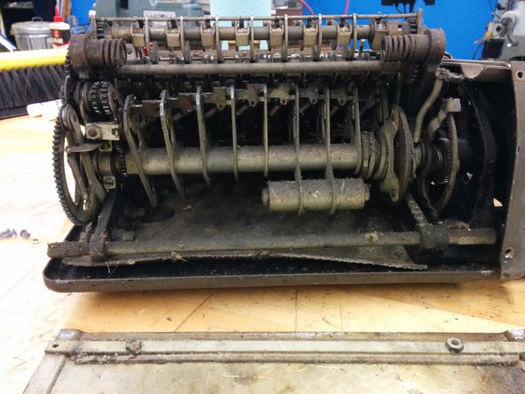
– Now, carefully remove the right side panel.
– Take a moment to check out what’s inside!
– Well, that’s not a pretty sight. Looks like dust has been having a party in there!
Step 8

– Take out these two screws—they’re #6-40, 1/4 inch in size. Once removed, drop them into bag #1 to keep everything organized. If you need help along the way, you can always schedule a repair.
Step 9

– Check the back panel for your device’s serial number (mine’s 143032). Jot your serial number down on every parts bag and on the box where you’re keeping the larger pieces. Keeping things labeled now means way less confusion later!
Step 10

Leave the handle alone for now! We’ll get to it later—no need to mess with it while working through the next steps.
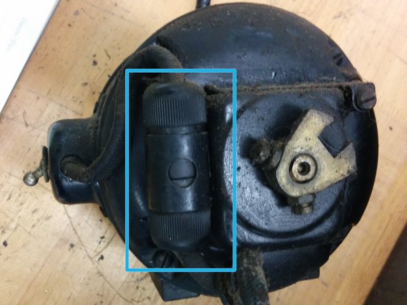
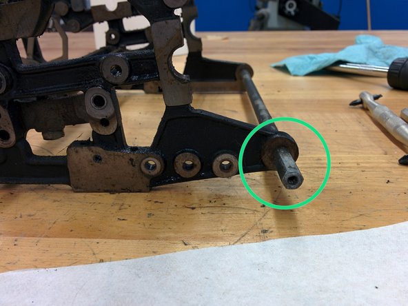
– To get the front panel off, start by removing the carriage shift handle. Chances are, it’s probably got some rust sticking it in place, but don’t worry—patience and a little lubricant will do the trick.
– Generously spray some penetrating lubricant onto the screw, the hole on the opposite side, and along the joining line. This will help loosen things up and make your removal smoother.
Step 11
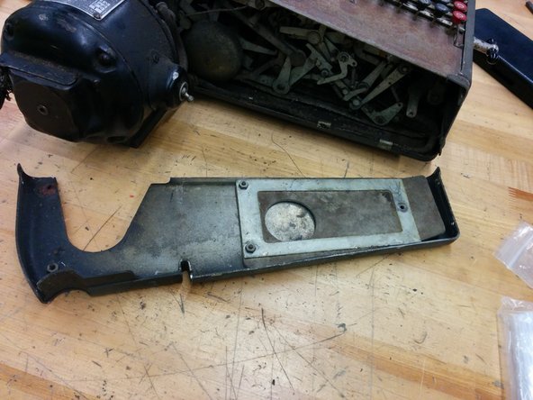

– Grab that #6-40 3/8″ screw and pop it into bag #1. Then, lift the component straight up and away. Keep it steady and gentle as you go.
Step 12

Let’s steer clear of that!
– Here’s a little backstory: when I was about eight, my dad brought home an old surplus calculator just like this one. I popped open this side first and was met with what seemed like endless layers of complexity.
– I fiddled with the buttons for a good hour, trying to make sense of it all. When that didn’t work, I gave it a few whacks with a hammer.
– This teardown is partly my way of saying sorry for that moment of frustration. It was the 70s, and hey, maybe disco had something to do with it.
Tools Used

Step 13

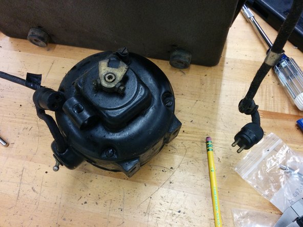
– Gently tip the calculator onto its right side so the motor is pointing straight up.
– Take out the two bolts and toss them into bag 1 for safekeeping.
– Set the calculator back down flat.
– Slide the motor off and unplug its wire from the calculator.
– Set the motor aside—don’t worry, it won’t roll away.
Step 14

– 1x tiny machine screw, #4-48, 1/4″, with a miniature head (just 1/8″ in diameter!)
– 8x machine screws, #6-40, each 1/4″ long
– 3x machine screws, #6-40, measuring 3/8″
– 1x machine screw, #8-36, at a length of 5/16″
– 2x hex head bolts, size 5/16-18, 7/8″ in length
– 2x split lock washers, sized at 5/16″
Step 15

– Grab a fresh bag labeled #2.
– Lift off the 80 numeric keys, plus the zero, repeat, and nonrepeat keys. Most will pop off with your fingers, but if you hit a stubborn one, grab some pliers. Slide the jaws beneath the key and gently pry it up—just toss a rag underneath to keep your calculator scratch-free.
– Drop all the keys into bag #2 for safekeeping.
Step 16

– Unscrew the add and subtract keys, they’re fastened with #4-48, 3/16″ screws. Grab a screwdriver and let’s get to work.
– Gently pull off the add and subtract keys, no need to rush, just ease them off.
– Place those add and subtract keys in bag 2, keeping everything neat and tidy.
– Start bag 3 and toss the screws in there. This way, you won’t lose track of anything!
Step 17

– 80x number keys – these are your workhorses, ready to type away!
– 1x zeroing key – the one that helps you hit reset, back to zero.
– 1x repeat (R) key – for those times you need to keep something going again and again.
– 1x nonrepeat (blank) key – when you need that space, but no repeats allowed.
– 1x add key – adding up the good stuff, one press at a time.
– 1x subtract key – for when you want to take something away or make room.
Step 18

– Take out the six screws shown here (#5-44, 1/4″ size).
– Drop those screws into bag 3 so they don’t wander off.
– Carefully lift off the entire decimal indicator assembly and set it aside.
– You’ll notice one side’s painted white, the other green—at least, that’s the rumor under all that dust!
Step 19

– Let’s tackle those six pesky screws! They’re #5-44, 1/4″. Once they’re out, toss them into bag 3 to keep things organized.
– Now, gently lift the top panel—start on one side and then the other—until it pops right off. It’ll come off along with the front panel, so no worries there!
– Once you’ve got the top and front panels off, set them aside for now.
– You might not be able to see it through the rusty exterior, but the top was once a lovely dark green!
Step 20

– Take a quick break and stretch your legs.
– Maybe see if you can spot a cool frog outside.
Step 21

These screws might have some split washers hanging out with them. Looks like they were meant to have one on each, but it seems like only half of them came with one. No worries, just keep an eye out for it!
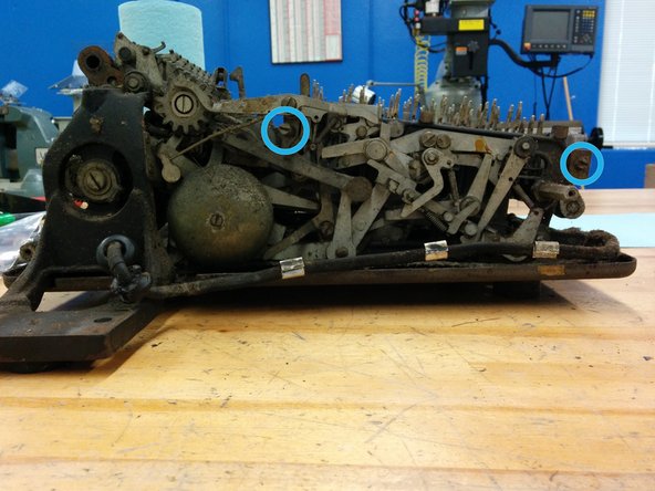
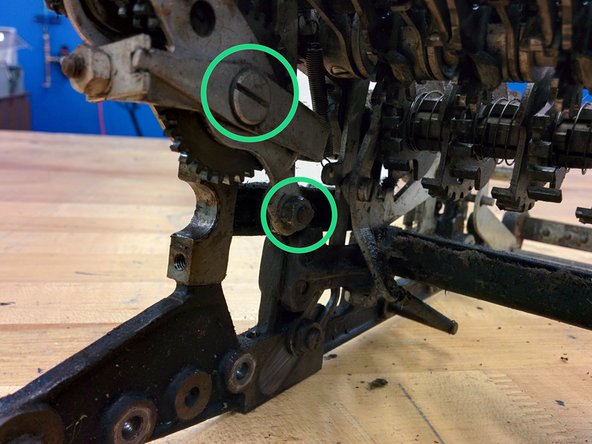
– On the right side, start by removing that screw in the front (#8-36, 5/8″) and then tackle the one that looks like a little shaft in the middle.
– That shaft-like screw? It’s a #8-36, 5/8″ screw with a 1″ head, 7/32″ in diameter. Not too tricky, right?
– Over on the left side, do the same! Remove the front screw (#8-36, 5/8″), then the shaft-like screw in the middle. This one is a bit longer though—it’s #8-36, 5/8″ with a 1-1/2″ x 7/32″ head.
– All these little guys go into bag 3. Nice and organized!
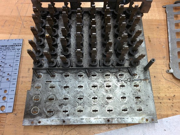
Step 22

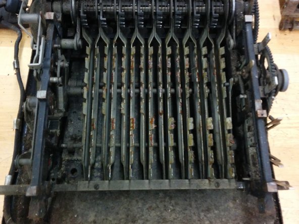
– Grab those front and rear bars and give a steady pull straight up—don’t be shy! With a bit of gentle persuasion, the whole keyboard module will pop right out.
– Set the entire assembly aside somewhere safe while you power through the next steps.
Step 23

– Let’s kick things off on the right side front! Unscrew that #8-36, 1″ screw and gently take off the washer.
– Toss them into bag 3 to keep everything organized.
– Next, go ahead and remove the switch and wire, then set them aside for now.
– Now, swing over to the left side front and remove the matching screw, #8-36, 5/8″.
– Don’t forget to drop it in bag 3 too!
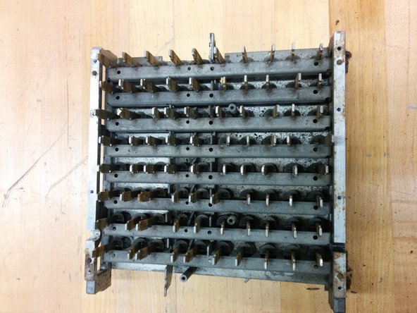
Step 24

– 12x #5-44 machine screws (1/4″ length)
– 2x #4-48 machine screws (3/16″ length)
– 3x #8-36 machine screws (5/8″ length)
– 1x #8-36 machine screw (1″ length)
– 3x #8 split lock washers
– 1x #8 flat washer
– (and the adventure continues!)
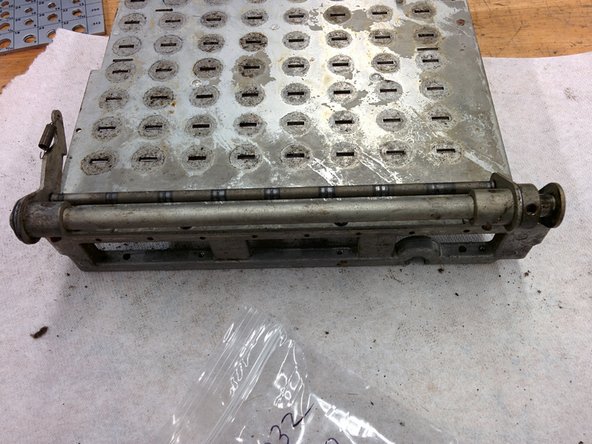
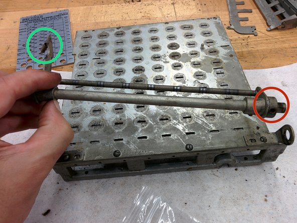
Step 25

– 1x threaded shaft with a 7/32″ diameter, measuring 1 5/8″ in total length and offering a travel length of 1″, #8-36.
– 1x threaded shaft with a 7/32″ diameter, measuring 2 1/8″ in total length and boasting a travel length of 1 17/32″, #8-36.
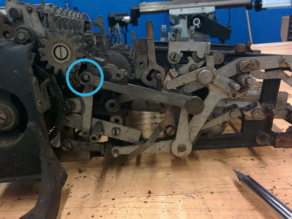
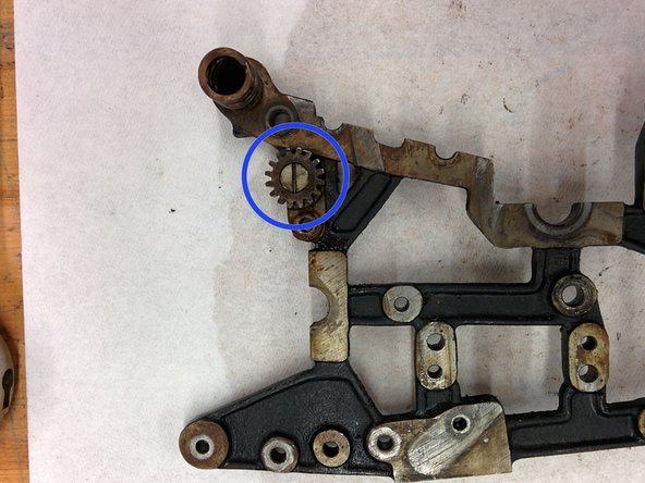
Step 26

– Start by getting a new bag ready, we’ll call it bag 4 – this will help keep all your parts organized.
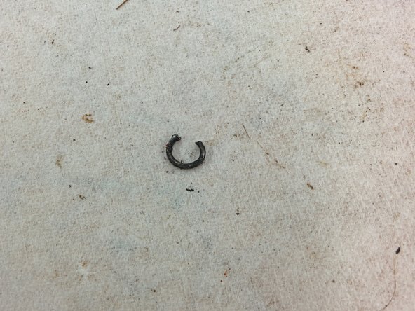
– Next, let’s tackle that retaining clip. To remove it, rotate the clip so the gap is facing upwards, then carefully hook your needle nose pliers into the ears and gently pull down. Don’t worry if the clip jumps out – it can be a bit tricky, but you’ve got this!
– Now it’s time to remove the washer. This should be a breeze.
– After that, remove the middle gear. You’re doing great!
– Finally, place all the parts you’ve removed into bag 4. Take a deep breath, you’re making progress! If you need help, you can always schedule a repair
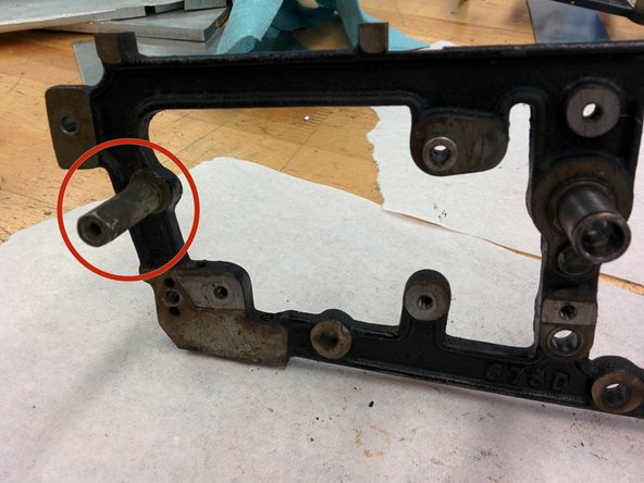
Step 27
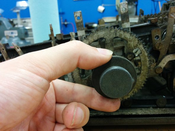

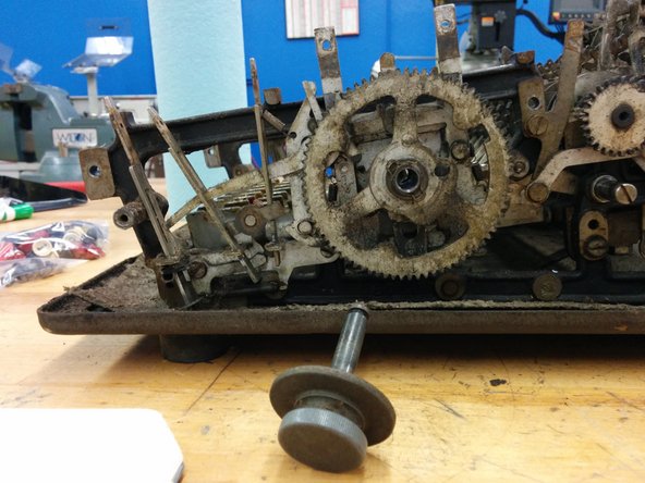
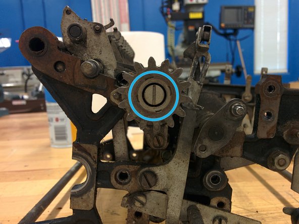
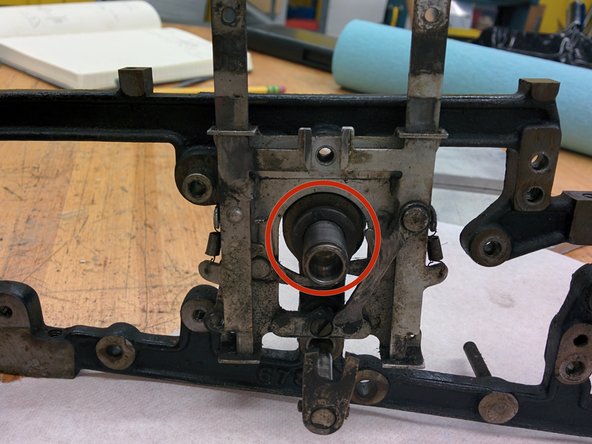
If the power’s out, no worries! Just pop off the cover plug and insert a crank to get things rolling. Although, it’s pretty rare to find one of these machines still rocking the crank—most have moved on.
– Using your finger, gently slide the cover plug release lever towards the front of the calculator.
– While keeping the lever in place, carefully pull the cover plug off its shaft.
– Toss the cover plug into bag 4 like a pro!
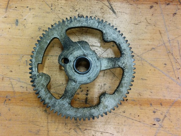
Step 28

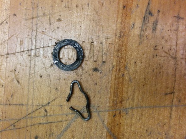
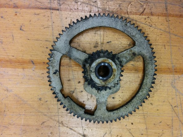
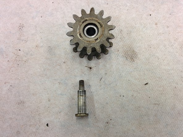
– Grab that 77-tooth gear, keeping an eye on those two timing markers!
– Next up, you’ll need a flat washer with a 1/2″ outer diameter and a 5/16″ inner diameter.
– Don’t forget the retaining clip made from 0.040″ wire – it’s a small but mighty component!
– Finally, make sure you’ve got a cover plug ready to seal things up nicely.
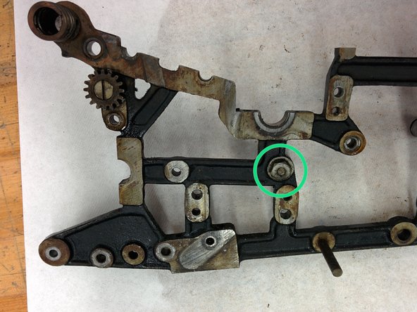
Step 29

– Get started with bag 5 – it’s time to put some pieces away!
– Just like you removed the middle gear, now it’s time to take out the retaining clip and washer from the crank gear – easy does it!
– Now, carefully place the clip, washer, and gear into bag 5 – you’re a pro at this!
Step 30

– Grab that 77-tooth gear with a single timing marker, it’s your trusty sidekick!
– Don’t forget the washer with a 5/8″ outer diameter and 7/16″ inner diameter—it’s essential for keeping things snug!
– And finally, make sure to include the retaining clip made of 0.040″ wire; it’s the unsung hero of the assembly!
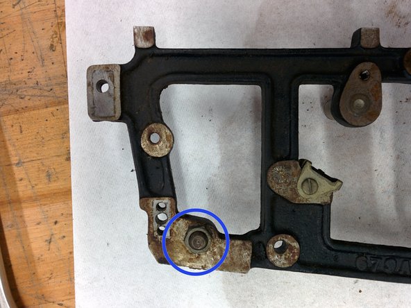
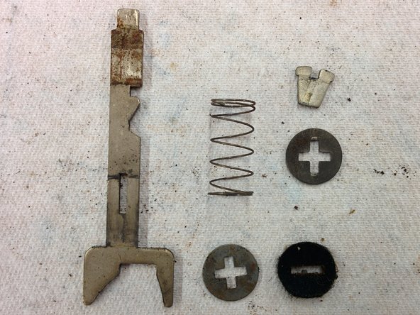
Step 31

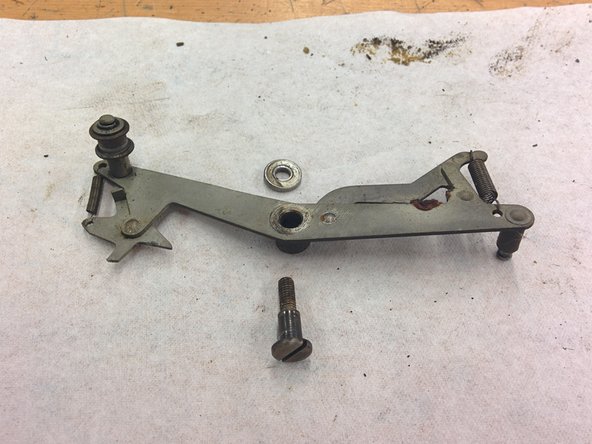
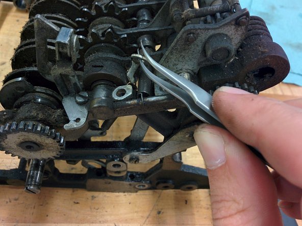
You can find this assembly detailed in the 1920 patent US1432616.
– Grab a fresh bag 6—you’ll need it!
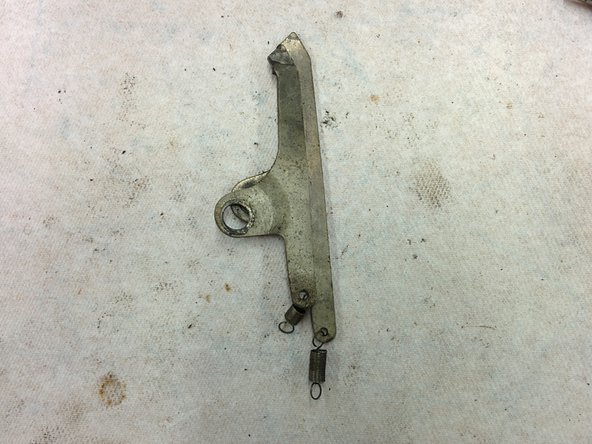
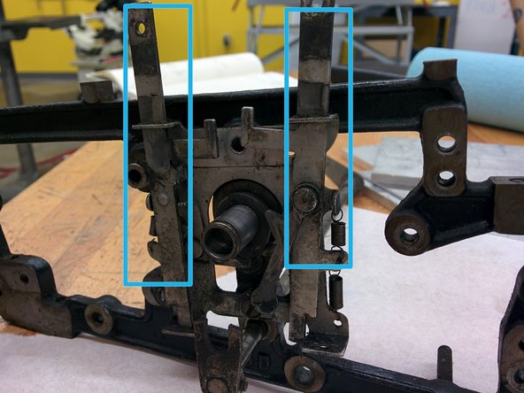
– On the front right side of your machine, unhook the repeat/nonrepeat detent spring from both ends.
– Remove the 5/16″ screw (#8-36, with a 0.1″ long, 7/32″ diameter shoulder) using your screwdriver.
– Take out the latch lever, and toss it in bag 6 along with the spring and screw.
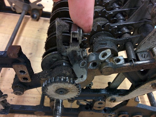
– Unscrew the next 5/16″ screw (#8-36) and add it to bag 6 too.
– Gently pull off the zero/repeat/nonrepeat key assembly and place it safely in bag 6.
Step 32

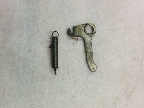
– 1x machine screw, #8-36, 5/16″
– 1x machine screw, #8-36, 5/16″ with 0.1″, 7/32″ diameter shoulder
– 1x expansion spring, 0.020″ wire, 3/16″ od, 13/16″ length
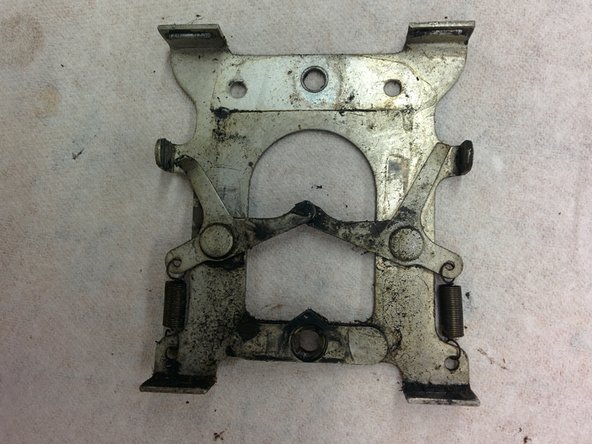
– Repeat/nonrepeat/zero assembly (2 parts)
– Latch lever
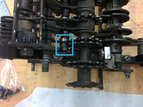
Step 33

– Grab a fresh bag 7 to keep things tidy. Now, swing around to the left back side of the machine and gently unhook the top two springs from the post they’re attached to. Easy does it! Next, locate that screw and give it a good unscrew. Keep in mind, there’s a nut on the other side of the frame, so hold onto it so it doesn’t roll away. Finally, carefully remove the bell mechanism and place all these parts into your bag 7 for safekeeping. If you need help along the way, you can always schedule a repair.
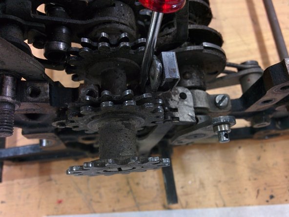
Step 34


– Go ahead and take off this part too, and toss it in bag 7.
– It’s time to unscrew the bell! You’ll need a #6-40, 1/4″ screw for this.
– Once you’ve got the bell and the screw, pop them into bag 7.
Step 35

No worries about bending or breaking this part. During reassembly, we’ll swap these out with retaining rings to keep everything secure and in place.
Back when these calculators were made, retaining rings weren’t a thing yet! The Seeger retaining ring didn’t show up in Germany until 1927, thanks to an inventor named Hugo Heiermann.
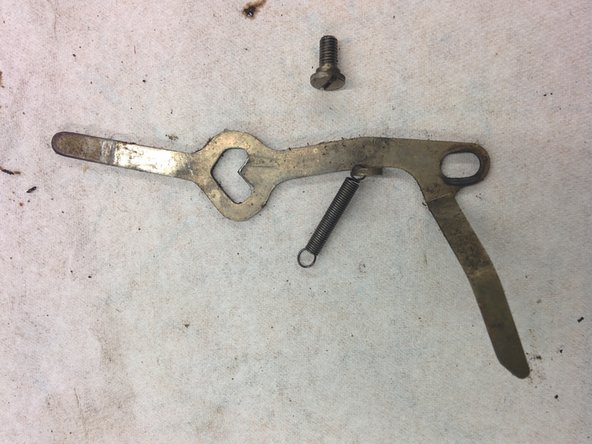
– On the left side, we’re taking off this lever.
– It’s secured by a retaining clip and a washer. The clip looks like a single loop from a chunky spring. Spot the gap in the wire, then grab your dental pick and a tiny screwdriver to gently open up the gap enough to slide it off with your needlenose pliers.
– Next, take off the washer (it’s got a 5/16″ outer diameter).
– Go ahead and unhook the spring’s end from its post, too.
– Drop the clip, washer, and lever into bag 7 for safekeeping.
Step 36

– Pop the spring out at the spot shown—don’t be shy, it’s tougher than it looks.
– Just like before, slide off the little wire and the washer (it’s about 1/2″ wide), along with the lever.
– Toss all those bits in bag 7 for safekeeping.
Step 37

Step 38

– Grab a fresh bag labeled 8—it’s time for a new round.
– Just like before: take off the retaining wire, washer, and lever. FYI, the washer has an outer diameter of 5/16 inch.
– Pop all these bits into bag 8 for safekeeping.
Step 39

– Now, let’s get that retaining wire, washer (1/2″ o.d.), and lever out of the way. Time to make some room!
– Toss those into bag 8 and keep things organized!
Step 40

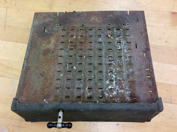
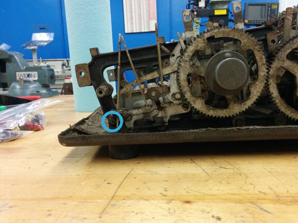
– Let’s get this repair started! We’ll begin by tipping the calculator onto its right side. Now, we’ll unscrew four of the five feet from the bottom – easy peasy, just turn them and they should come right off, no screwdriver needed.
– If they don’t budge, we might need to bust out the screwdriver, but hopefully it doesn’t come to that.
– Now that we’ve got the feet removed, we’ll stash them in bag 8 for safekeeping. We’re making great progress – keep it up!
Step 41

– Give it a gentle tug and set it aside. The bottom mat might be a little clingy, so just keep pulling until it lets go.
– Flip the calculator over so it’s upside down.
Step 42

Step 43

– Time to kick off bag 9!
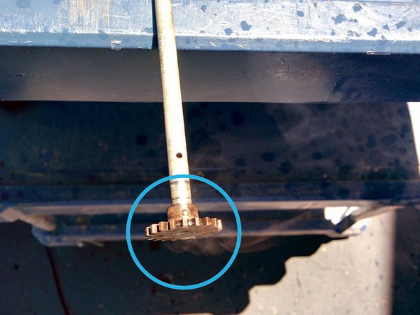
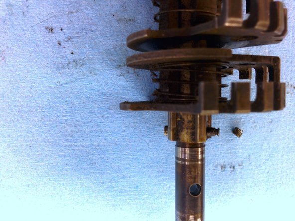
– Now, let’s focus on the left side (which has magically turned into the right side after the flip, but we’ll keep calling it the left side). Unscrew the set screw, #6-40, 3/16″, from the collar.
– Go ahead and unscrew it all the way. Toss it into bag 9.
– Give that collar a little twist and slide it down the shaft just a smidge. This will help loosen it up. You’re likely in the clear without needing any penetrating lubricant or lubricating penetrant.
Tools Used

Step 44

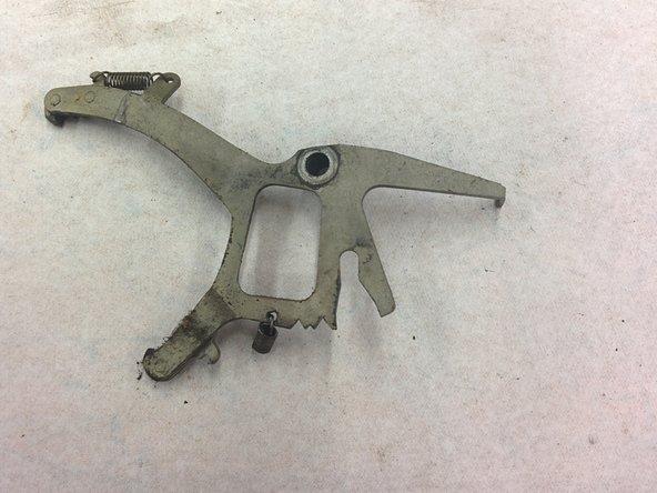
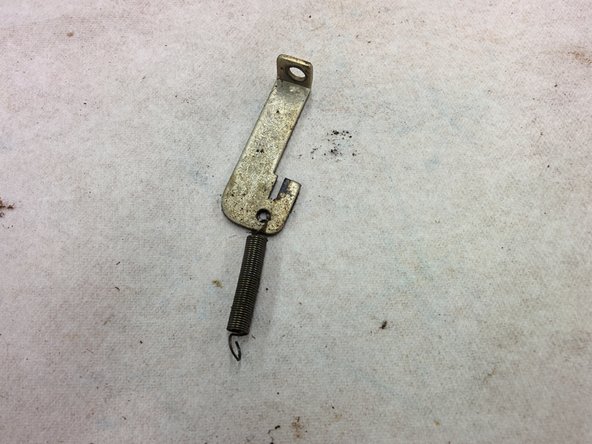
Looks like the spring on my device is out of commission! I’m a bit puzzled about where it was meant to connect.
– Turn the calculator back the right way up, just like flipping a pancake!
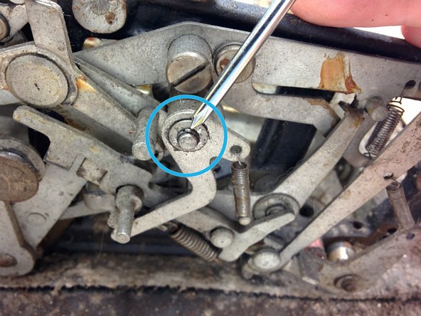
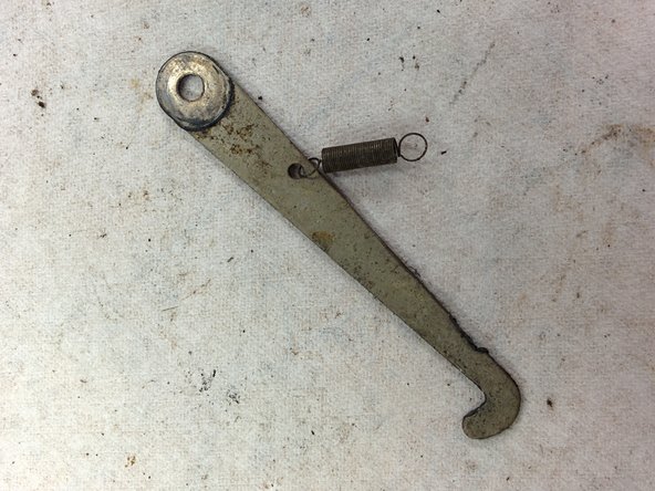
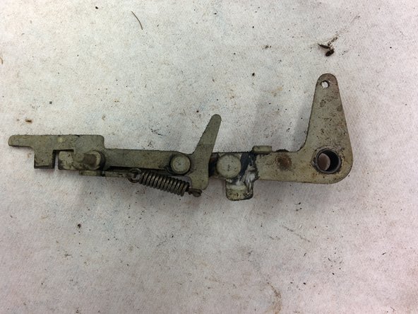
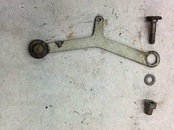
– On the left side, let’s tackle that screw. It’s a 3/16-32, 1″, and has a 1/4″ diameter shoulder. Toss it into bag 9 for safekeeping!
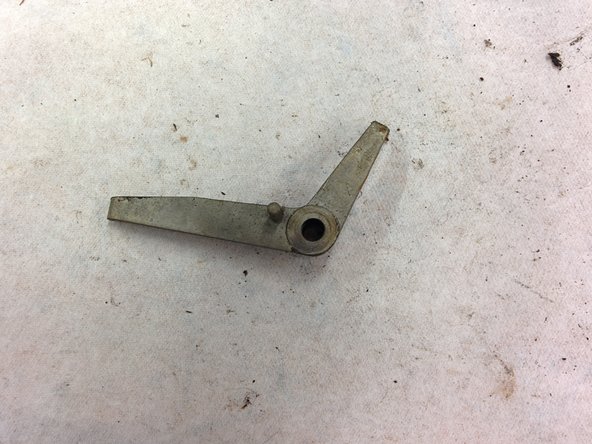
– Now, let’s get that lever off. You might need to wiggle it a bit to set it free. Don’t forget to put it in bag 9 too!
Step 45
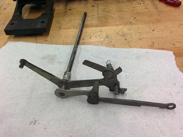

– Flip to the inside of the left frame and unhook the big spring from its spot. (No sweat—it’s just hanging out there.)
– Now swing around to the outside of the same frame. Bend that cotter pin and ease it out of its hole. Toss it in bag 9 for safekeeping. If it snaps, don’t stress—it’s a piece that’s easy to swap.
– Slide the whole lever assembly (shaft and all) straight out. Keep things smooth and move along the direction of the shaft. You might need an extra hand to nudge the shaft collar off the other end.
– Pop the collar into bag 9, and park the lever/shaft assembly somewhere safe for now.
Step 46

Heads up: there’s a 7/16″ o.d. washer hanging out between the lever and the frame. Don’t let it make a break for it—catch it before it rolls away!
– First up, on the left side, take out that screw (#8-36, 3/4″, 7/32″ shoulder). A little twist and it’s out!
– Next, carefully remove the lever. Pop all the parts into bag 9—let’s keep things organized!
Step 47

– Carefully unhook the spring from its post—no springy surprises here!
– Remove the screw, size #8-36, 3/8 inch long with a 7/32 inch shoulder—keep it safe!
– Gently take out the lever and pop it along with the screw into your bag 9—ready for the next step.
Step 48

– You’ve got this.
Step 49

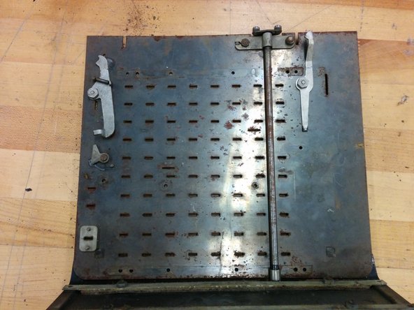
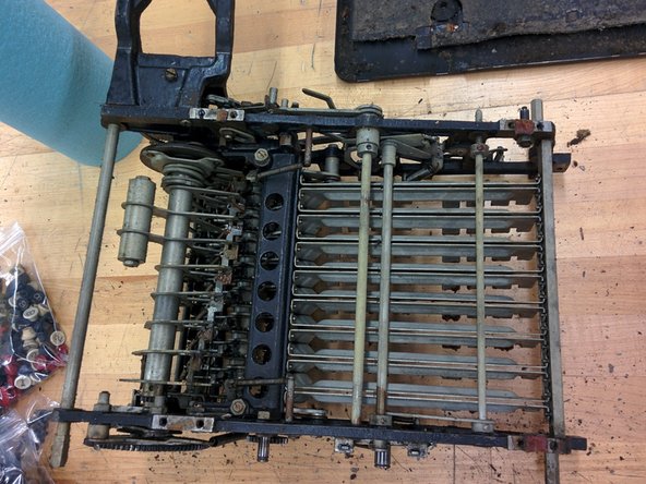
– Take out those two #4-48, 1/4″ screws and toss them into bag 9 for safekeeping.
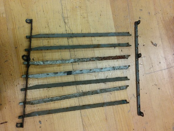
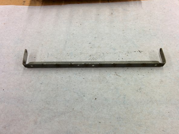
– Pop off the retaining bar to free up the parts you’re working on.
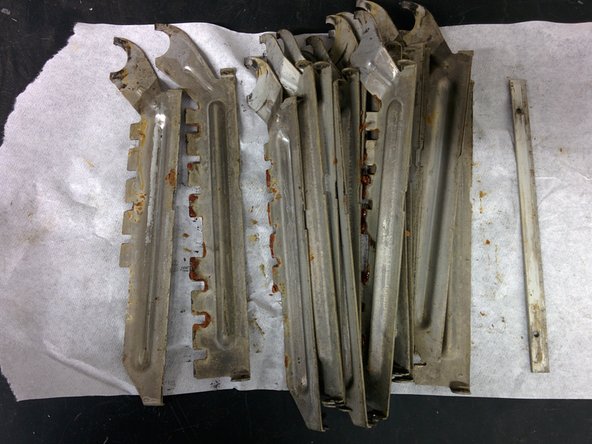
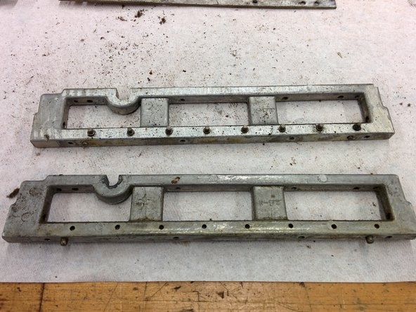
– Grab a few paper towels—these rock bars are gonna be greasy, so better safe than slippery.
– Carefully remove the rock bars, wrapping them in paper towels so they stay clean and manageable. We’ll give them a proper cleaning later.
– Don’t forget to also place the retaining bar in with the rock bars for safekeeping.
Step 50

Step 51

– Kick off a new Bag 10 adventure!
– The oiling tube takes a dive into a cozy hole in the collar.
– On the left rear side, say goodbye to this screw and toss it in Bag 10.
– Time to send the oiling tube on its journey into Bag 10.
– Unscrew this 3/8″ nut and give it a home in Bag 10.
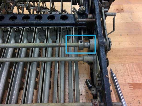
Step 52

– You might have spotted this from the bottom if you’d taken it off first — just a heads up! The model number here is KA-163, which tells us it’s a 16-digit accumulator with 3 registers (the main accumulator plus two counters). The rest of the digits make up the serial number. If you need help, you can always schedule a repair.
Step 53

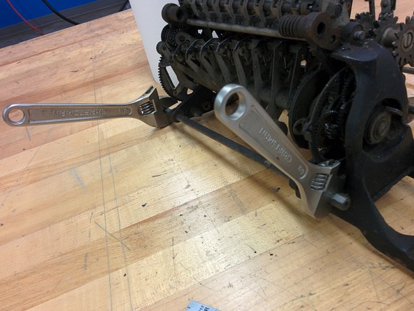
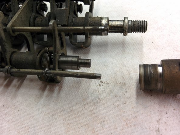
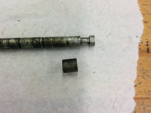
– Loosen the 3/8″ hex standoff from the threaded shaft. It should come off with a little twist.
– You might need a wrench to keep that shaft from spinning, but honestly, it’s probably not necessary.
– Pop the standoff into bag 10 for safekeeping. Easy peasy!
Step 54

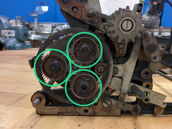
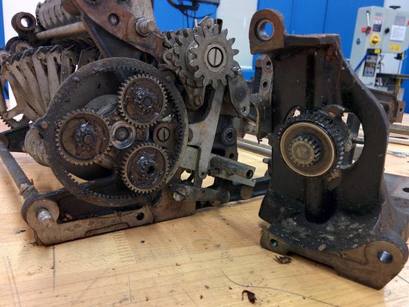
– Give the motor mount a little wiggle and gently pull it away from the frame. It might take a bit of finesse, but you’ve got this!
– Set the motor mount aside carefully, so it doesn’t get in the way.
– Next, slide out the three 36t/12t gears. They should come right off. Pop them into bag 10 for safekeeping!
Step 55
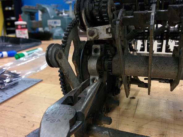

– On the back right side, take out those two screws.
– Pop those screws into bag 10 so they don’t make a break for it.
– Gently slide the spring off its lever and toss both into bag 10 for safekeeping.
– Lift out the axle half-bushing and let it join the party in bag 10.
Step 56

– On the back left side, let’s get those two screws out of the way.
– Next up, it’s time to take off the half-bushing. Just a heads up, it has a nice big arc and a little hole where the oil from the oiling tube makes its grand entrance.
– Now, toss those screws and that half-bushing into bag 10 to keep them safe.
Step 57

– A little gentle coaxing, and the entire carry/drive shaft assembly should come right off.
– Now, just slide off that motor drive gear like it’s no big deal.
– Go ahead and set those parts aside for now – we’ll need them later.
Step 58

– On the rear right side, loosen and remove this screw—it’s a 3/16-32 with a 1/2″ threaded length—and take out the spring at the marked spot. Since there’s a nut on the other side, grabbing a wrench to hold the nut steady will make things easier. If the screw refuses to come off the lever or if the large bushing between the lever and frame won’t budge, don’t force it—just move on to the next step. When you’re done, tuck everything into a bag labeled ’10’ to keep track of your parts. Need a hand? You can always schedule a repair with Salvation Repair.
Step 59

– Start by removing the screw measuring 3/16-32 with a threaded length of 13/32 inch—remember, there’s a nut on the other side holding things together. Next, note that a 3/8-inch outer diameter washer with a thickness of 0.047 inch is nestled between the lever and the frame—don’t forget to set it aside carefully. The screw features an eccentric shoulder, which means it has an off-center part that needs special attention. Finally, place all these parts into bag 10 to keep everything organized as you go. If you need help at any point, you can always schedule a repair.
Step 60

– Start by removing two screws: the #8-36, 10/32″ and the 3/16-32 with a 7/16″ threaded length. Next, detach the lever assembly carefully. Finally, place all removed parts into a bag labeled ’10’ to keep everything organized. If you need additional help, you can always schedule a repair.
Step 61

– Let’s take a peek inside bag 10 and see what treasures await!
Step 62

From this point forward, let’s say that any small parts you take off will happily find their way into the current bag.
– Grab a fresh bag and let’s get to work!
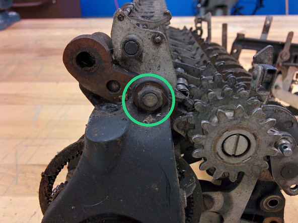
– From the rear right side, unscrew the 5/16″ hex nut, #6-40, and it’s 0.095″ thick. Easy does it.
– On the inside of the right rear side, remove that 5/16″ hex nut (it’s 0.156 thick) and the #6-40 screw (1/4″)—this should be a breeze.
– Now, gently take out the lever that was being held by that screw. You’re almost there!
Step 63

– Gently wiggle the clutch assembly away from the frame, then rotate it downward and pull it off. Next, slide the gear right off—no tools needed, just a little patience. If you need help along the way, you can always schedule a repair.
Step 64
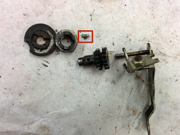

Keep an eye on this tiny key! It plays a crucial role in keeping the clutch parts lined up as they slide back and forth. Missing it could cause trouble down the line, so handle with care. If you need help, you can always schedule a repair.
– Just slide each of these parts right off—no wrestling required!
Step 65

– Bag 11, reporting for duty! What’s hiding inside? Let’s find out.
Step 66

– Kick off with bag 12, let’s get organized!
– Now, on the inside right rear, gently take out that #8-36, 1/2″ screw along with the eccentric nut. You’ve got this!
Step 67

– On the rear right side, unscrew these three screws—using a 5/16″ #8-36 screwdriver—and set them aside. Next, find the middle screw securing a part with a spring hook. Carefully unhook the spring from the hook. Finally, pull back the lever and gently manipulate the loose component you just unscrewed from the third screw to remove it. If you need a hand, you can always schedule a repair.
Step 68

– On the left rear, unscrew these three #8-36, 5/16″ screws. Easy peasy.
– The screw on the right is a bit of a challenge. Grab a long, thin screwdriver, loosen it just a bit, then switch to a smaller one to get it all the way out.
– That right screw? It’s holding two parts together, so make sure you’re ready to separate them.
– The left screw has a hook for a spring that runs along the length of the machine. You’ll probably need to detach a small piece of the larger surrounding spring first. Once you’ve done that, hook the end of the inner spring onto the bushing. Simple enough!
Step 69

– On the back left side, take out the screw labeled #8-36.
– Next up, remove the #8-36 screw with the 1/4″ shaft.
– Slide the gear off—this one’s got a groove where the screw sits, so keep an eye on that.
– Now, slide off the gear on the right side. This one’s smooth—no groove here. Heads up: if you find this gear in a different spot later on, you’re not losing it—just double-check the order!
Step 70

– On the rear right side, take off the 5/16″ x 0.095″ hex nut. Inside, unscrew the matching screw with the shaft.
– From inside, tap out the 3/16-32 screw.
– Now, carefully remove the clutch support you just freed from the screws.
Step 71

– So, what surprises await in bag 12? Let’s take a peek!
Step 72

– Grab a fresh bag and let’s get started with step 13!
– On the left rear side, take out that screw (3/16-32, 7/16″) that’s holding those two levers in place.
– Now, it’s time to unhook the lever springs. Remember, the lever with the shorter arm and spring goes in the front, so keep that in mind.
– Oh, and don’t forget there’s a washer between the screw head and the first lever. It’s 9/32″ in diameter and 7/64″ thick, just in case you were wondering.
Step 73

– Unscrew that bad boy, 3/16-32, 1/2″. Let’s get that screw out of the way!
– Pop off the lever and take out the bushing that’s chilling between the lever and the frame.
Step 74

– Time to get that screw out! Grab your #8-36, 1/2″ screw, and carefully remove it, along with its plate and the washer (5/16″ outer diameter, 1/8″ thick) that’s sandwiched between the plate and the frame. Easy peasy!
Step 75

– Take out the driver wheel assembly. Carefully pop the two axles out of their four half-moon cradles—no need to muscle it—and set them aside for later.
Step 76

– Take out the #8-36, 1/2″ screw with the eccentric nut (yep, that’s the one).
– Next up: pop off the levers on both the right and left sides. Heads up—the tabs on top of both levers point to the left, and the lever from the left side has its middle tab bent inward, just to keep things interesting.
Step 77

– Wondering what’s hiding in bag 13? Let’s find out!
Step 78


– Kick things off with a fresh bag 14.
– On the right and left rear sides, unscrew four #8-36, 5/16″ screws.
– Pop off the semicircular half-bushings.
– Carefully pry up and out the selecting gear assembly. Two clips are holding the axle, just give it a gentle pull.
– Set the selecting gear assembly aside for now.
Step 79


– On the inside left, unscrew that #8-36 screw. You’ll also find a hex nut (5/16″ x 5/32″) hanging out on the opposite side of the frame.
– Next, gently remove the clip and lever.
– Keep things in order: screw, clip, lever, frame, nut. It’ll make reassembly a breeze!
Step 80


– On the right side inside, take out this screw (#8-36). There’s a 3/16″ x 5/32″ hex nut hanging out on the other side of the frame.
– Slide off the lever and the clip—easy does it.
– Pay attention to the order (it’s not the same as the left side!): screw, lever, clip, frame, nut.
Step 81

– What’s in bag 14?
Step 82

– Begin by setting up a new bag 15. Then, on the right side, locate and remove this screw—it’s a 3/16-32 x 5/8″ fastener. Take your time and keep track of all the pieces. If you need help, you can always schedule a repair.
Step 83

– On the left side, take out that screw, 3/16-32 x 5/8″ and the split washer, 5/16″ od x 0.085″. You’ve got this!
Step 84

– On the left side, pop that spring off its post on the frame, but leave the other end attached to the part. Easy does it.
– Next up: there’s another spring hanging out on two posts. Go ahead and remove it completely. Quick fun fact—it’s 3/16″ wide with a 0.012″ wire diameter.
– Swing around to the right rear side and unscrew the hex spacer. It’s got a #8-36 thread, so don’t wrestle with it—just a gentle twist will do.
Step 85

– What’s inside bag number 15?
Step 86

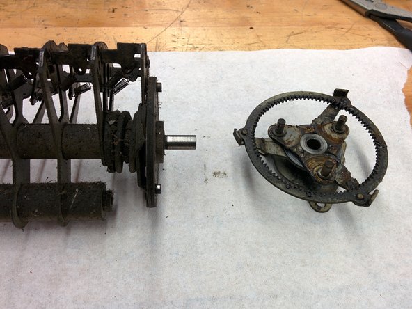
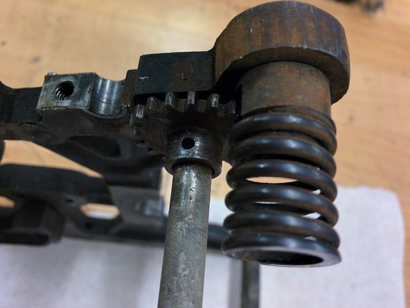
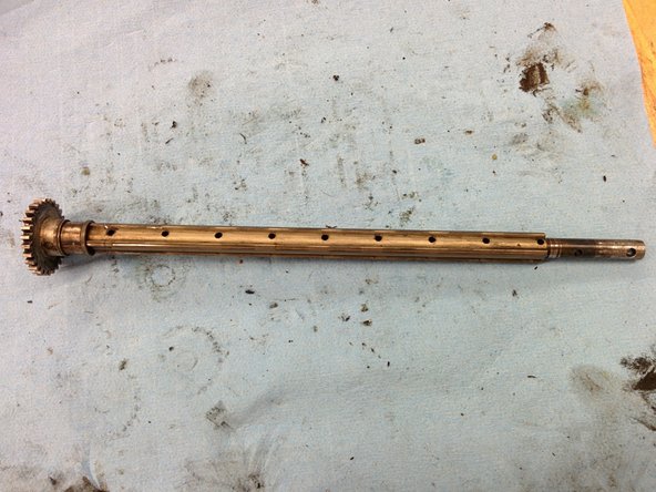
Taper pins are a big upgrade over set screws—once they’re in, nothing’s spinning out of place. The trade-off? After 90 years, getting one out is a whole new adventure.
– Right now, the only thing keeping these two frames joined is this gear. It’s snugly fixed onto the shaft with a taper pin. A taper pin is a special kind of pin that tapers from a wider end to a narrower end, and it’s used to secure parts onto a shaft. To set it up, the machinist places the gear on the shaft, drills a hole through, then shapes the hole with a tapering reamer. After that, they insert the taper pin, give it a few gentle taps with a hammer to seat it properly, and grind down any excess sticking out. If you need help, you can always schedule a repair.
Tools Used
Step 87

– Before you dive into removing those taper pins, treat yourself to a satisfying stretch. Limber up—your tools (and your muscles) will thank you!
Step 88

Take this step outdoors or crack a window—fresh air is your friend!
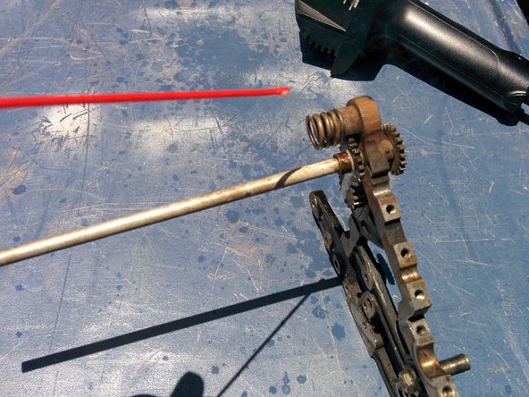
– Let’s get that part loose! Take a heat gun and give it a good two-minute blast to get it up to max temperature. Don’t worry, it won’t melt or anything.
– Time to bring in the big guns – penetrating lubricant! Spray some on the part and watch as it starts to work its magic. You’ll see a bit of smoke, but don’t panic, it’s all good.
– As the lubricant starts to evaporate, give it another spritz until it stops disappearing into thin air. This means the part has cooled down a bit, so it’s time to heat things up again.
– Repeat this heat and lubricant dance a few more times – we’re talking three more cycles, to be exact. The goal is to break the bond between the taper pin and the part, and sneak some lubricant into that teeny-tiny gap between them.
– After a few rounds of heat and lubricant, you should be able to remove the taper pin from the part. If not, don’t worry – it might just need a bit more convincing. Take your time and be patient, and you’ll get there!
Tools Used

Step 89

– Bring the part over to the arbor press. Support it against a surface that provides plenty of contact area, but still allows the taper pin to move freely at the bottom. A good choice is a piece of aluminum with a semicircular groove—this can be made by drilling a hole and then cutting halfway through the diameter, or by using an appropriately sized endmill. Next, cut a smaller notch along the length of the groove to give the pin room to move. This step can be done with a drill and saw or with an endmill. If you need assistance, you can always schedule a repair.
Tools Used

Step 90

– Use calipers to measure the width of each end of the pin, aiming to identify the smaller end—this is usually the trickier part. In most cases, the smaller end is ground flush with the part on one side and sticks out on the other. For larger taper pins, remember that the rounded end is the bigger side, while the flat or smaller end is on the opposite. Position your part securely in the arbor press, ensuring the small end of the pin is facing up and supported by your jig. Carefully press on the pin with the arbor press, applying steady pressure. If you find you’re nearly maxing out your strength and the pin isn’t budging, try applying a bit more heat or lubricant cycles. Still no movement? Double-check that you’re pressing on the correct end of the pin—if not, refer to the next step.
Tools Used
Step 91

– If you tried pushing out the pin and it’s just not budging, or if both ends are flush so there’s no way to push, grab a 1/16″ end mill (not a drill) and carefully drill a little off each end.
– Hit it with a few rounds of heat and some lubricant—think of it as a spa day for stubborn pins.
– Now, take a 1/16″ flat pin punch and tap the pin with a hammer. No need to go full Hulk—gentle taps work best, or the pin might get even more stuck.
– Still stuck? Looks like you’ll have to drill out the whole pin. It’s a pain, since you’ll need a new pin when you put things back together, but sometimes it’s the only way. If you get stuck, you can always schedule a repair.

Step 92

– Now that the arbor press has done its job and moved the pin, it’s time to carefully tap it out with a 1/16″ flat pin punch and a hammer. A little precision goes a long way, so take it slow and steady!
Tools Used
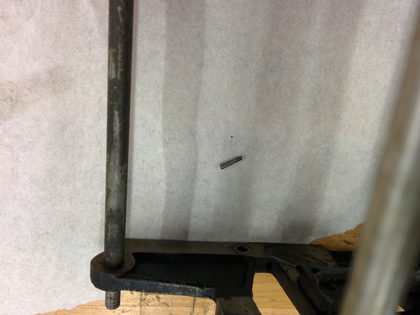
Step 93

Take a look at the picture! The second shaft from the right, the one with the spring, will come off too. Be careful though, don’t let that spring roll away – it’s easy to lose track of!
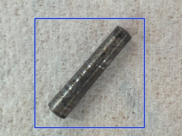
– Begin by creating a new bag. Carefully remove the taper pin from the gear located on the upper left side. Once free, bag the taper pin—it’s approximately 0.086″ at the wide end, 0.071″ at the narrow end, and around 0.410″ in length. This results in a taper ratio of about 1/2″ per 12″, which is not a standard taper pin size—modern standards typically use 1/4″ per 12″. If the wide end measures 0.080″, then the taper aligns with current standards; perhaps the pin was slightly widened during installation. Next, gently disassemble the frame—slide the gear off its shaft. You might need to pry off the larger iron piece in the middle and shift one side of the frame at a time. Eventually, the sides will come apart. Finally, remove the rightmost rectangular component and the shaft second from the right. Set aside the rectangular part, and bag the spring. If you need help, you can always schedule a repair.
Step 94

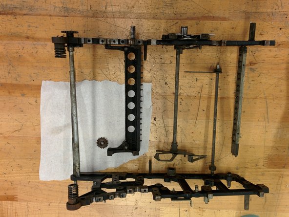
– Next, go ahead and carefully remove the shaft with threaded ends from the far left and set it aside for now.
– With that done, the left frame is now free. Go ahead and place it somewhere safe while you move on.
Step 95

– From the right frame, gently pop off the iron crosspiece and give it a little space of its own. You’ve got this!
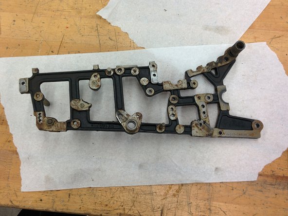
Step 96

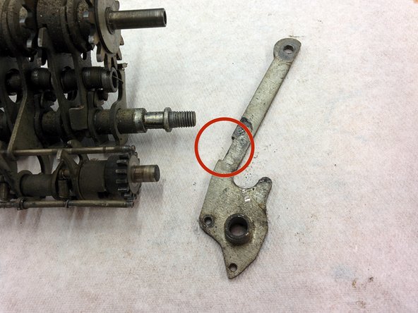
– Start by unscrewing the screw on the right side of the frame. There’s a tiny nut on the other side that you should try to hold steady or loosen just a bit. If it’s stubborn, no worries—just turn the screw slowly, and the nut will resist with plenty of friction, making the job easier. Need a hand? You can always schedule a repair.
– Next up, gently remove the spring from its post on the frame, then take out the lever.
– Finally, the nut should now slide right out, completing this step.
Step 97

– Curious about the goodies packed in bag 16? Let’s dive in and see what surprises await you!
Step 98

– Kick off with a fresh bag 17!
– Gently pop out the inner taper pin and gear from the shaft at the back.
– Carefully slide the shaft out of the right frame.
– Next, remove the last taper pin and gear from the shaft.
– Now, just set the shaft aside for a bit.
Step 99

– Loosen this set screw—don’t take it out all the way—and slide the ring over a bit.
– On the right frame, there’s a cam ring hanging out. If it’s still there, go ahead and remove it.
– Now you can wiggle these levers loose. First, pop off their springs. You’ll probably need to slide the shaft out a bit too.
Step 100

– Start by unscrewing that #8-36, 3/8″ screw. It’s got a flat head, but don’t let that fool you – it’s got a bit of a triangular twist to it.
– Next, gently detach the assembly from the frame and bag it up. Keep it safe!
Step 101

– Let’s get that taper pin and part off the right side of the shaft, shall we? It’s time for a little extraction action!
– Now, this taper pin is a bit of a heavyweight compared to the previous ones: measuring 0.112″ at the big end, 0.096″ at the small end, and stretching a full 0.517″ long. It’s got a taper that’s nearly 3/8″ per 12″, which is a tad unconventional.
– But hey, if that wider end were a cool 0.107″, we’d be talking standard pin territory here!
– Now, smoothly slide the shaft out of the frame, and gently slide that bushing right off the shaft.
Step 102

– Slide the taper pin out, then remove the part from the opposite end of the shaft.
Step 103

– Wondering what’s inside bag 17? Let’s take a quick peek to see what tools or parts are included. If you find yourself needing a hand during the process, remember you can always schedule a repair with Salvation Repair for extra help. Now, let’s get started!
Step 104
– Grab a new bag 18 and get ready to dive in.
– On the front side of the right frame, use your trusty tool to take out the 1″ hex standoff with the 3/16-32 threaded male end. Don’t forget that washer (O.D. 0.379 x 0.048) hanging around.
– In the middle of the inside of the right frame, it’s time to tackle that 3/8 nut. There’s a split washer inside and a regular one on the outside, plus a little screw-in post with 3/16-32 threads that needs to come out.
– Flip to the back of the right frame and unscrew the #8-36 screw holding the gear in place.
Step 105

– Head to the front of the left frame and loosen up the 1.5″ hex standoff with a 3/16-32 threaded male end. Don’t forget to grab the washer that’s tagging along.
– Now, shift to the middle of the left frame. Unscrew the #8-32 spring post, remove the washer, and take off the piece it’s been holding in place.
– Next, on the front inside of the left frame, take off the 3/8 nut and the spring post 1/4-28 screw. Keep track of those parts!
Step 106

– Take out that standard #6-40 screw and its nut. Next, lift off the padded rest—easy does it!
– That’s all there is for the frames! You’ve officially wrapped up the main body disassembly.
Step 107


– Time for a little break – how about a pirate ride? You’ve earned it!
– Just a heads-up: make sure your iPhone is secure before moving forward.
Step 108

– Wondering what’s in bag 18? Let’s take a quick peek! It’s packed with everything you need to get the job done. No need to stress; you’ve got this!
Step 109
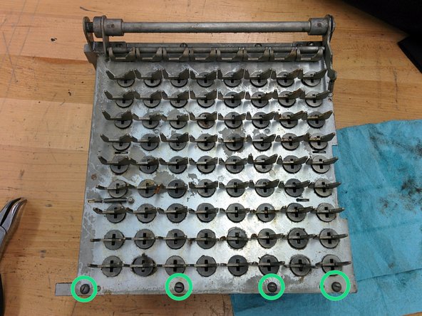

– Time to dive into the keyboard assembly! Set up five new bags and label them 19A to 19E.
– Detach the spring from the keyboard baseplate.
– Flip the keyboard assembly so the clearing shaft is up, then take out these four #4-48 screws and their lock washers. Drop them in bag 19E.
Step 110
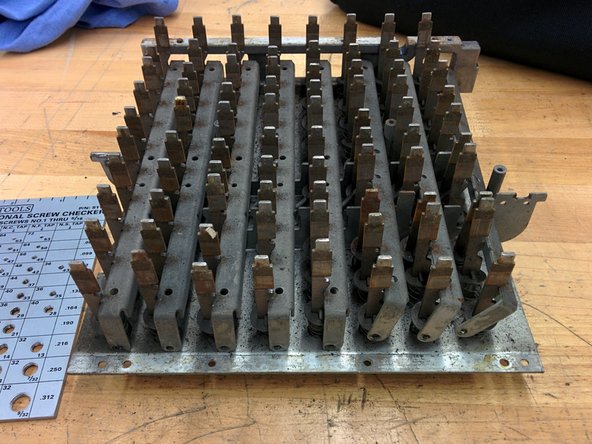

– Flip the keyboard assembly over and gently lift the frame up and then out. The frame has pins that let the lock bars for each row spin into place.
Step 111

– The lockbars come with springs attached, so let’s tackle those! Start by gently unhooking the spring end on the lockbar side to remove the lockbars. For now, keep those springs cozy with the base plate.
Step 112


– Flip the keyboard over and gently unhook both ends of that spring. Toss the spring into bag 19E to keep it safe. Turn it over again and remove the two horizontal clear locking bars. Keep in mind, the bars are practically twins—except one has an extra riveted piece. The riveted one sits higher and points left; the other is lower and points right, just like in the picture. If you need help along the way, you can always schedule a repair.
Step 113

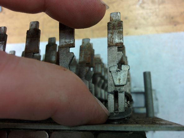
– Start by pressing down on the washer for each key to get it loosened up.
– Then, gently lever out the key stem retainer that’s nestled in its slot.
Step 114

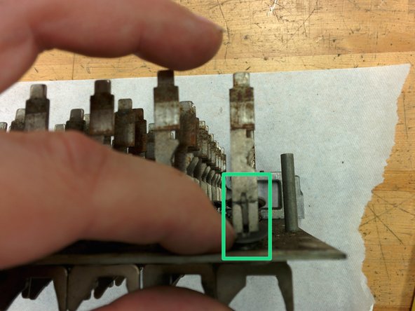
Heads up! The zero keys don’t come with bottom washers or felt washers, so keep that in mind as you work through this step.
Just a heads-up: the zero key stems are designed with a little curve to fit snugly around the zero shaft. Make sure they line up just right for a smooth setup!
– First, carefully lift the washer and spring off the top of the key stem.
– Next, gently pull the key stem out from the bottom. You’ll find a metal washer and a felt washer tucked inside.
– Now, organize the parts: pop the key stems into bag 19A, metal washers and retainers into 19B, felt washers into 19C, and the key springs into 19D.
– Repeat this for all the keys.
Step 115

– Unscrew the set screw holding that bushing in place and toss it in bag 19E. We’ll need it later!
– Now, give the bushing a little twist and wiggle to loosen it up. It should come right off.
Step 116

– Gently slide the whole shaft to the right and lift it out from the left bushing—like you’re sneaking out of a crowded row at the movies.
– Next, pull the shaft out of the right bushing. Easy does it!
– Take the bushing that’s still hanging out on the shaft and drop it into bag 19E for safekeeping.
– Find the spring that’s left behind, and send it to join its buddy in bag 19E.
Step 117

– Check out the serial number now revealed—matching and ready! Next, remove these four screws along with their lock washers. Keep them together, and place both the right and left bushings into bag 19E for safekeeping. If you need help at any point, you can always schedule a repair.
Step 118

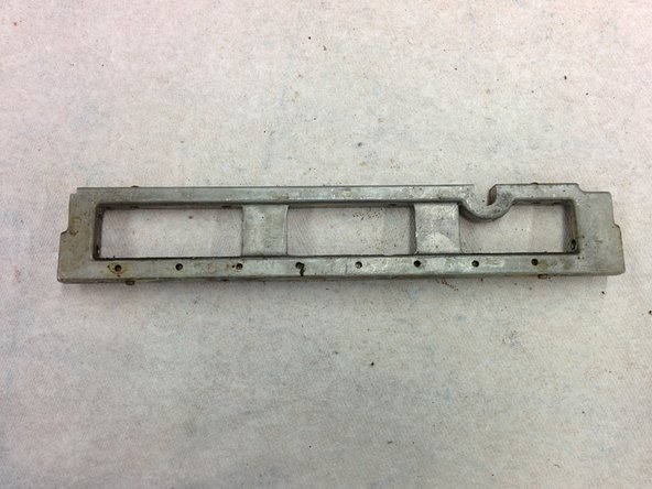
– Flip the keyboard plate over and carefully take off the frame piece.
– Now you should have two frame pieces in your hands—pretty simple so far!
– Next, remove the eight springs from the spring strip and pop them into bag 19E. You’ve got this!
Step 119

– Start by counting your key stems: there are 8 zero key stems and 72 non-zero key stems. This breakdown helps you know what you’re working with before diving in. Ready? Let’s get those keys sorted and ready for reassembly. If you need a hand along the way, you can always schedule a repair.
Step 120

– Gather 152 shiny metal washers and 80 trusty retainers to get started on your repair adventure!
Step 121

– Start by gathering your parts: 80 key springs and 72 felt washers. These tiny components are crucial for the smooth operation of your device. Carefully keep track of them as you go along. If you run into any trouble or need a hand, remember you can always schedule a repair with the pros at Salvation Repair. Proceed gently and take your time—precision makes perfect!
Step 122

Looks like the set screw took a hike and a lock washer decided to go missing. No worries—just double-check your parts before proceeding, and if you need a hand, you can always schedule a repair.
Step 123

– Hooray! You’ve successfully disassembled the keyboard assembly! Nice job!
– Why not take a moment to treat yourself to a little reward?
Step 124

Keep an eye on how everything lines up—getting parts back in the right spots will save you a headache later!
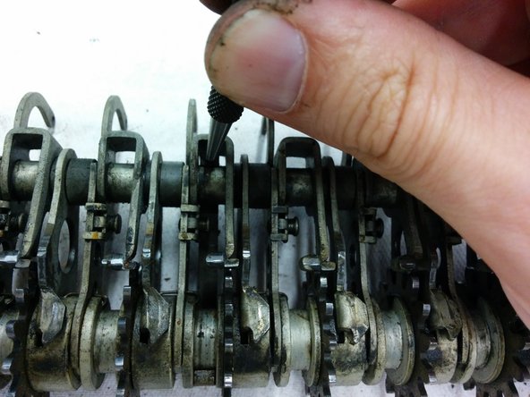
This is how it works: when you press a key, rock bars move the plates inside the assembly. This action selects the same number of teeth as the key you pressed, which then engages the other gears. It’s like a little dance of parts working together to make things happen!
– Grab bag 20 and 20A! Bag 20 is where you’ll toss the parts, and 20A is for those big, separating springs that are coming up soon.
– Time to remove that taper pin!
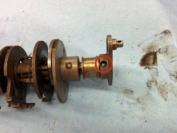
– Once that’s out, you can easily slide off two parts: the crank and the bushing. Make sure to bag them along with the taper pin.
Step 125

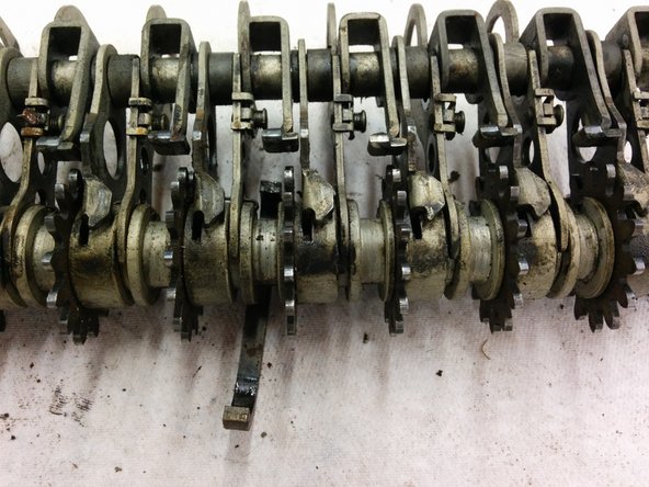
– Pop out that taper pin.
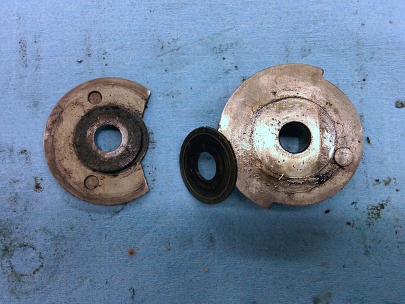
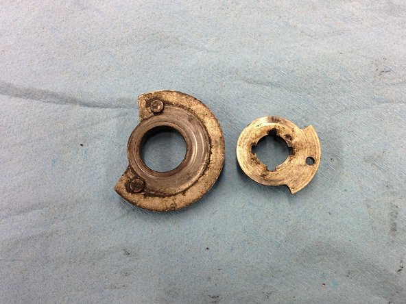
– Once it’s out, three pieces will come loose: a big locking cam, a washer, and a small locking cam. Keep an eye on them—they like to roll away!
Step 126

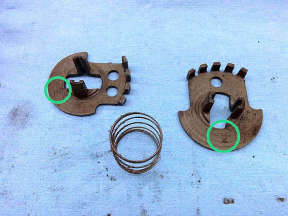
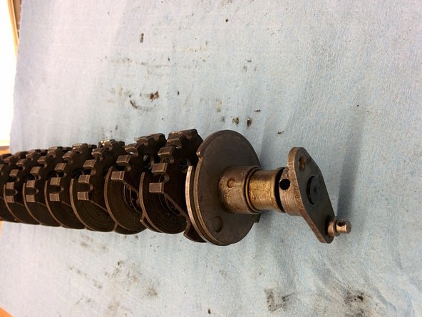
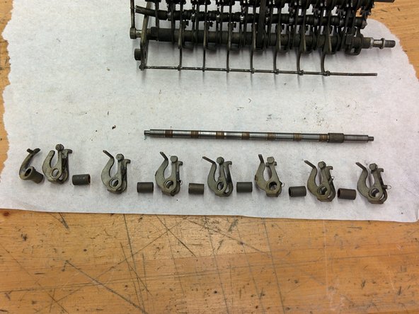
– The gears are paired up with facing teeth, separated by a spring. Between each pair, there’s a stop pin held in place by a few turns of a retaining spring. Use a super thin screwdriver (around 1mm works well) to gently pry out the end of the retaining spring—once loosened, it should slide right off the pin. Now, you can set aside the retaining spring, pin, gear pair, and their separating spring. Be sure to put the large separating spring into bag 20A. Each gear pair has a number—make a note of the sequence! My order was: 9, 10, 7, 6, 5, 4, 3, 2. After noting the sequence, carefully remove all the gear pairs to proceed with the repair. If you need help at any point, you can always schedule a repair.
Step 127

– Next up, there’s a pair of cams that can slide right off after the gears. Just give them a gentle nudge.
– What’s left on the axle now is a gear and a bushing. The gear is snugly held in place by a pin, so no worries about it wandering off!
Step 128
Step 129
Step 130


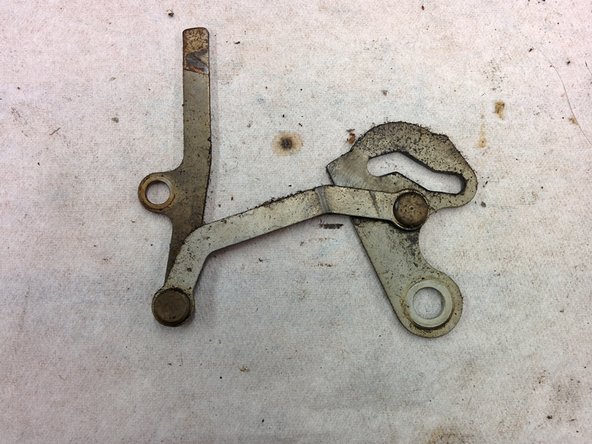
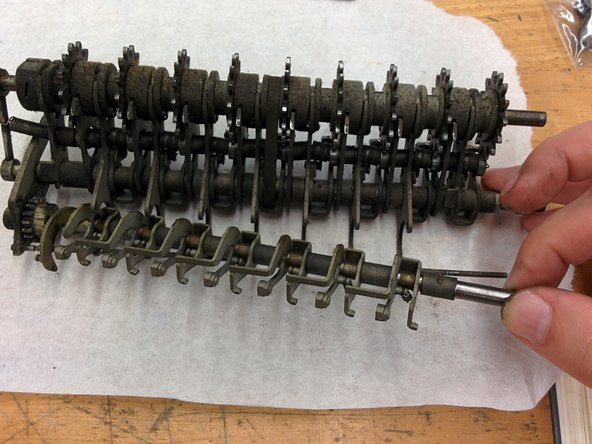
– Now let’s carefully take apart the intermediate gear assembly and see what’s inside. Keep your spirits up—you’re doing great!
Step 131

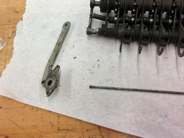
– Begin by setting up a new bag 21A and 21B, and place the small parts into 21B for safekeeping. With the assembly sitting face-up and the side levers pointing down, carefully remove the retaining wire. Now, about that rod below—it’s a bit of a mystery. I’m not entirely sure if it also had a retaining wire or if it just snapped off on its own. Interestingly, the two rods are actually different from each other. Take your time with these steps, and if you need additional help, you can always schedule a repair.
Step 132

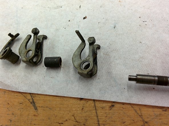
– Gently remove the side lever.
– Keep an eye out for that little notch in the lever! Just a heads-up, the side lever on the left side is notch-free.
Step 133

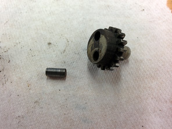
– Start by pulling off the driving gear that spins the eccentric axle.
– Next, remove the pin from the gear to free it up.
– Finally, take out the eccentric follower from the axle to complete the step.
Step 134


– Next up, gently pull out that quirky-shaped lever from the axle, along with its spring, giving it a friendly tug.
– Then, slide the washer off the axle with a smooth motion.
Step 135

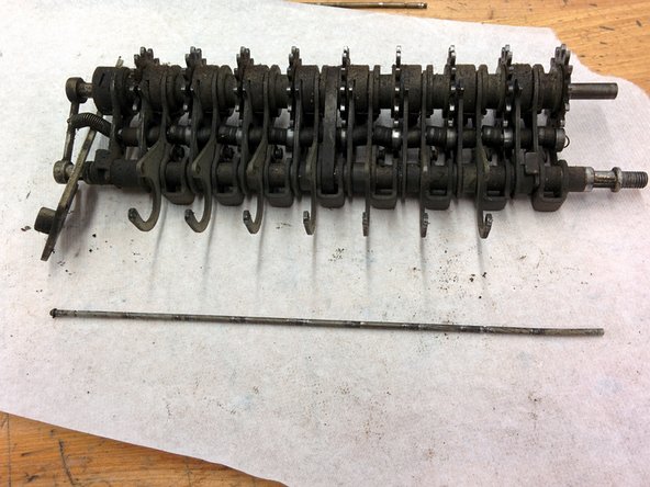
– Slide the top rod out from the left side—don’t forget to bring along its trusty retaining wire.
– Next up, remove the bottom eccentric axle assembly. Easy does it!
Step 136


– Take out the eccentric driver gear from the left side — easy peasy!
– Next, remove the two levers from the left side of the eccentric axle — you’re doing great!
Step 137

– Start by carefully removing the bushing to free up space.
– Next, detach the quirky-shaped lever to continue disassembly.
– Keep at it, removing each part methodically until everything has been taken out.
Step 138

– Pop the retaining wire off that last rod—give it a little wiggle if it’s stubborn.
– Slide the wire out from the left side.
– The left lever will come off, too. Don’t worry, this one’s notch-free, unlike its right-side buddy.
Step 139

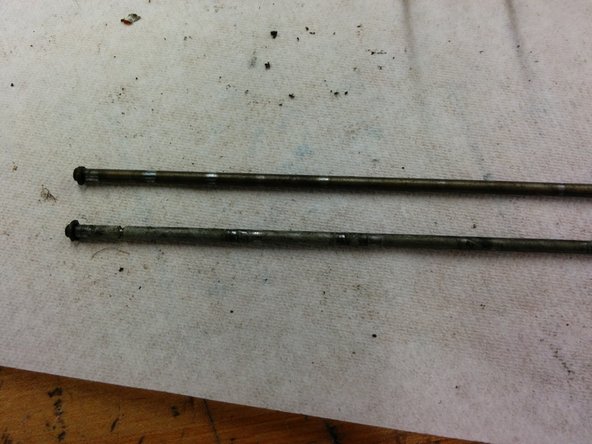
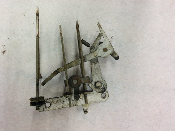
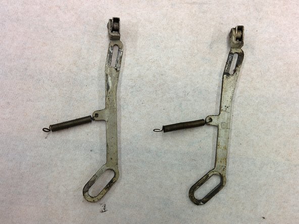
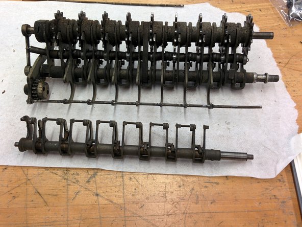
– Pay close attention to the difference between the top rod and bottom rod, which are shown here with their right sides aligned, then with their left sides aligned. This helps keep everything organized and makes the repair smoother. If you need help, you can always schedule a repair.
Step 140
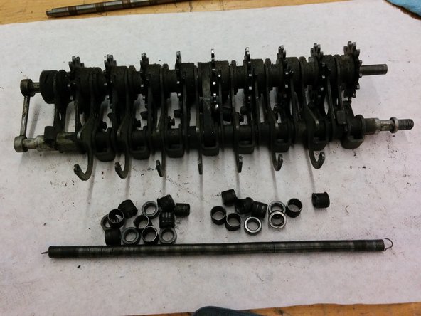

– Detach that detent spring with a little finesse.
– Once you get the hang of it, you can smoothly pull the long spring out, bringing along the other springs and bearings for the ride!
Step 141

– There’s a strap keeping the two axles in place. Time to show it who’s boss!
– Flip the assembly over and gently tap the strap with a punch and hammer to release it.
Tools Used
Step 142
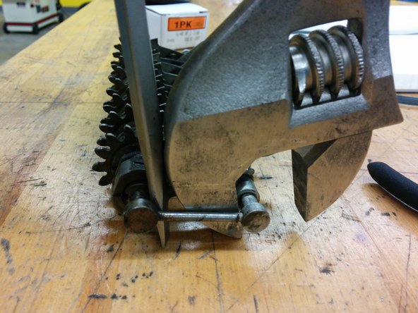

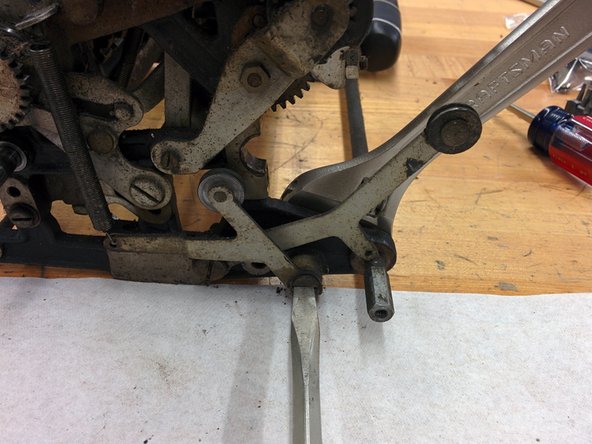
– The two axles are now hanging on by this long pin. It’s the only thing keeping them together.
– Grab a wrench and a screwdriver, and gently but firmly work the pin out. It’ll come free with just a bit of elbow grease!
Step 143

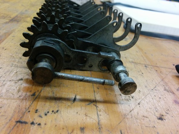
– The two axles are now apart. Let’s tackle the top axle first.
Step 144
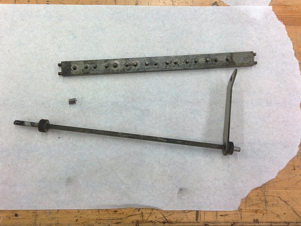
– Let’s take a peek at what’s inside bag 21A, shall we?
Step 145
– Time to check out what’s inside bag 21B!
Step 146

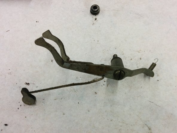
– Start by grabbing a fresh bag 22.
– On the left side, you’ll see a few things to remove: a small lever, a long bushing, a large lever, and a short bushing.
– And at the very end, there’s an extra-long bushing waiting to be taken off.
Step 147
– What’s hiding in bag 22? Let’s find out together!
Success!