Motorola Droid RAZR Antenna/Headphone Jack Replacement
Duration: 45 minutes
Steps: 19 Steps
The main wireless antenna and headphone jack are tucked away inside the large plastic housing at the top of your Droid RAZR. It’s a bit hidden, but not impossible to reach. Just follow the steps carefully, and you’ll have it all sorted in no time!
Step 1


– Let’s get started by inserting a plastic opening tool between the back cover and rear case at the lower left edge of the back cover. This is where the magic begins!
– Now, gently pry the back cover up with the plastic opening tool to release those plastic clips. You’re making great progress!
– Continue prying along the left edge of the back cover towards the top of the phone. You’re almost there, keep going!
Step 2


The top edge of the back case is super slim, so go easy when prying to keep it from cracking or snapping.
– Use your plastic opening tool to gently work across the top of the back case, popping those plastic clips free.
– Keep going down the right side, prying carefully to release the last of those stubborn clips.
Step 3


Keep the battery in place and avoid removing it along with the back cover, or you might accidentally break the power lead. Stay cautious, and if you need help, you can always schedule a repair.
The back cover is glued to the battery pretty tightly, so you’ll need to put in a little elbow grease to get them apart.
Made from Kevlar, the back cover can handle a lot of twisting and pulling without giving up on you.
– Gently pry off the back cover from the phone and set it aside. It’s a simple move, just give it a little nudge, and you’ll be all set!
Step 4


– Gently use the spudger’s tip to lift off the red silicone cover that’s protecting the battery terminal screws. Once you’ve got it up, just remove it and move on to the next step!
Tools Used

Step 5


The battery is stuck pretty well to the motherboard with some adhesive. Take it slow to avoid any unwanted bends or crinkles in the battery.
Your phone’s motherboard is equipped with metal EMI shields, which cover the ICs – a bit different from what you see in this photo.
– Use your T5 Torx driver to take out the two 3.3 mm screws holding down the battery terminal. They’re small but mighty.
– Grab that blue pull tab and gently lift the battery out—like you’re helping a friend up from the couch. Battery, be gone!
Step 6


Be careful when tackling these steps – we didn’t use a heat gun, and let’s just say the camera cover can get a little cranky if the adhesive isn’t warmed up first. It cracks easily, so take your time and be gentle.
– Warm up the adhesive under the camera cover with a heat gun or a hair dryer – it’ll make things a lot easier.
– Gently lift the bottom edge of the camera cover using a plastic opening tool.
– Carefully slide the plastic tool along the bottom edge to release the cover from the sticky adhesive.
– Keep using the heat gun if needed to keep that adhesive soft while you work your way around the camera cover.
Tools Used

Step 7


– Slip your plastic opening tool under the top edge of the camera cover—like you’re sliding a spatula under a pancake.
– Ease the cover up gently, gliding your tool along the top edge to loosen that sticky adhesive.
– Lift off the camera cover and set it aside. Nice work!
Step 8

– Time to unscrew! Take out the six screws holding the rear case on your phone:
– Up top: three shiny 6.7 mm silver T3 Torx screws,
– In the middle: four 4.0 mm gold T3 Torx screws,
– And at the bottom: three 4.5 mm black T5 Torx screws.
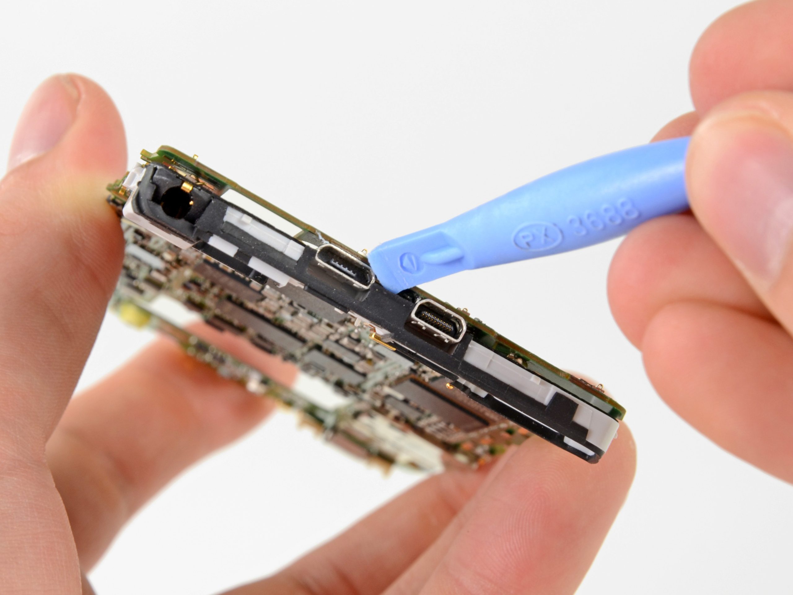
Step 9


– Slide a plastic opening tool between the rear case and the motherboard assembly. No need to rush, just let it slip in nice and easy.
– Now, work your way down the side of the phone. Gently wiggle the tool and pry up the rear case—just enough to pop it loose.
– Carefully separate the rear case from the motherboard assembly. It’s like peeling back the layers of a phone burrito, but without the mess!
Step 10


– Take out the three 2.5 mm T3 Torx screws holding the metal chassis to the motherboard. Set those little guys aside somewhere safe.
– Lift the metal chassis off the motherboard assembly.
Step 11


– Let’s get started! Use the flat end of a spudger to carefully pry off the two red silicone microphone covers located at the top and bottom of the motherboard. Take your time and work gently to avoid damaging any surrounding components.
Tools Used
Step 12

– Grab your trusty spudger and gently nudge those clips out of place. Once they’re bent just right, the shield will come right off, no problem.
There’s a tiny metal shield hiding over the display assembly cable connectors on the motherboard. This little guy is kept in place by a few small clips that latch onto the surrounding EMI shields. Just gently unclip it to reveal the connectors underneath. Need a hand? You can always schedule a repair.
Tools Used
Step 13


– Take the flat end of your spudger and gently pop off those three display cable connectors from the motherboard—easy does it, no rush!
Tools Used
Step 14


You’ll find a bunch of small black plastic clips securing the display assembly to hold the motherboard snugly in place. These little guys keep everything aligned and secure, so take your time to gently detach them when needed. If you need help, you can always schedule a repair.
– Gently pop open those securing clips with your trusty plastic opening tool. A little wiggle and you’re all set!
Step 15


– Warm up the adhesive holding the motherboard in place with a heat gun or hair dryer. Just enough to make things flexible—no need to roast it.
– Gently work a plastic opening tool around the edges of the motherboard, lifting it away from the display assembly. Take your time—no rush.
– Carefully lift out the motherboard assembly. You got this!
Tools Used
Step 16


– Let’s get started by carefully lifting the anti-static tape that’s covering the camera and earpiece ZIF connectors. Use the tip of a spudger to gently pry it up.
– Now, peel back the tape and remove it completely. Try not to tear it, as you might need it again later.
– If you don’t have any spare ESD-safe tape handy, consider setting this piece aside in a safe place for when you’re ready to reassemble everything. It’s always a good idea to hang onto useful bits like this.
Tools Used
Step 17


Aim your prying tool at the tab, not the connector—let’s keep things in one piece!
– Time to get started! Use a plastic opening tool or your fingernail to gently pry up the tab on the rear-facing camera ribbon cable ZIF connector – it’s like opening a little door.
– Now, carefully push the rear-facing camera through its hole in the grey antenna and remove it. You’re making great progress!
Step 18


Be sure to pry gently on the tab, not the connector itself. You don’t want to accidentally give the connector a bad day.
– Time to get started! Use a plastic opening tool or your trusty fingernail to gently pry up the tab on the front-facing camera ribbon cable ZIF connector.
– Now, carefully lift the front-facing camera out of the antenna using your plastic opening tool, and voila! It’s removed.
Step 19


– To wrap up your repair, simply follow these steps in reverse – easy peasy!
– You did it! If you need help with another repair or have any questions, you can always schedule a repair
Success!