NEC PC-FX Teardown
Duration: 45 minutes
Steps: 13 Steps
The PC-FX was a 32-bit home video game console created by NEC and Hudson Soft, hitting shelves in 1994 and hanging around until February 1998. It was designed as the follow-up to the TurboGrafx-16, but unlike its predecessor, the PC-FX was exclusive to Japan. If you need help with your device, you can always schedule a repair.
Step 1

After removing these screws, you should easily be able to slide off the left and right panels.
– Flip your console over and say hello to the four T10 screws hiding underneath. They’re what’s keeping those left and right side panels from going anywhere—so grab your trusty screwdriver and set them free!
Step 2

– Gently pop off the front panel—there are three clips on each side holding it in place. Check out the picture: the top two clips on the left are highlighted for you.
Step 3

– Now that the front panel is out of the way, gently lift the top panel. It’s held in place by three clips on each side, so give it a little wiggle. Just a heads-up: the top panel is still connected to the daughterboard by the lid sensor connector (as shown in the second picture). Don’t yank it off just yet.
– To fully release the top panel, carefully disconnect the lid sensor connector. That’s your cue to lift it away completely!
Step 4
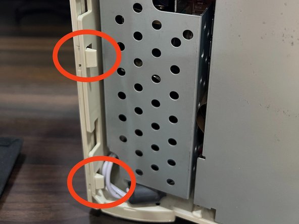

Now that you’ve tackled those rear screws, let’s pop off the rear panel! It’s held snugly by three clips on each side. Check out the second picture to spot the two lower clips on the left side (looking from the front).
– Let’s start by taking off the rear cover. Unscrew the two Phillips screws at the back first. Remember, when you’re putting everything back together, you’ll need to reassemble in the reverse order: Rear, then Top, then Front. If you need a hand along the way, you can always schedule a repair.
Step 5

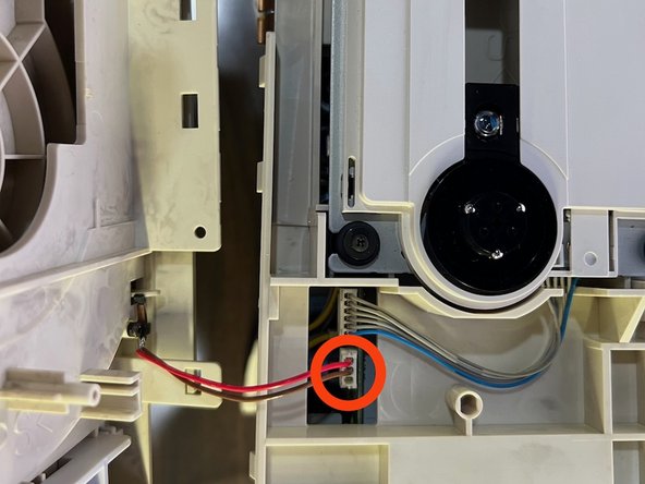
– Let’s start with the CD drive. Gently lift the tabs that are holding the drive ribbon connector on the left and the power connector on the right (unless you’ve already done that).
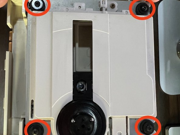
– Unscrew the four tiny Philips screws on each post keeping the drive in place (these are shown in the second picture). Once that’s done, you can carefully lift the drive up and remove the springs under each post.
– There’s a transparent plastic sheet that keeps the ribbon connector secured. It’s a good idea to remove it entirely—it’ll make plugging the drive back in a whole lot easier.
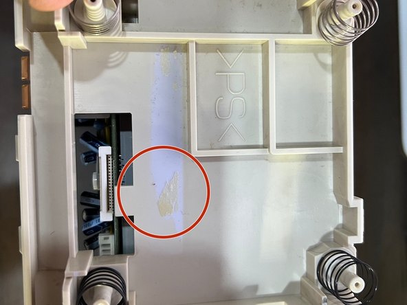
– The third picture shows the sticky residue left behind after removing the clear plastic sheet.
Step 6

– Take out the 8 Phillips screws outlined in the image. For the lower left screw, just nudge the power cable aside to get to it. The lower right screw also keeps a ground cable in place, so make sure to free that too.
– Next up, remove the daughterboard shield—it’s the large one to the right of the Power Board.
Step 7
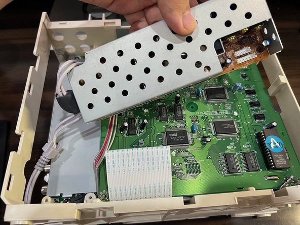

– First, unplug the 4-pin power connector from the daughterboard to the powerboard (the one with the yellow wire). Do the same with the 5-pin power connector from the motherboard (that’s the red wire).
– Once you’ve got those disconnected, you can remove the power board. You might need to pull the power cable all the way out from the inside, just like you see in the second picture.
Step 8

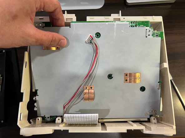
– Start by carefully disconnecting the main ribbon cable from the daughterboard.
– Once that’s done, the daughterboard should pop right out – nothing else is holding it in place!
Step 9

– Take out the four screws at the corners and the three longer screws in the middle of the motherboard. Keep it steady and keep track of those screws—don’t lose them! If you need help along the way, you can always schedule a repair.
Step 10

– Here comes the fun part: time to lift out the main motherboard! Gently bend the top of the plastic frame upward while coaxing the upper edge of the motherboard toward you.
– It might get a little fiddly, so keep an eye out for any stubborn bits of frame plastic blocking your way. If things aren’t budging, just give that top edge of the frame a bit more flex and you should be good to go.
Step 11

– Now that the motherboard is free, go ahead and gently release the three clips around the expansion port bays. That’s it – you’re done with the teardown! Nice work!
Step 12


That’s a wrap on the teardown! To put everything back together, just work through these steps in reverse. Before you dive in, check out the next step for some handy reassembly tips to make things go smoothly. If things get wild, you can always schedule a repair.
Step 13

– When putting any of the three expansion port bays back in, make sure the lower ‘lip’ slides between the PCB and the shielding underneath. If it’s not sandwiched in just right, the Rear, Top, and Front panels won’t snap together the way they should.
– To reinstall the motherboard, do the reverse of how you removed it: slide in the bottom of the PCB first, then gently flex the top frame while pressing down the top edge of the PCB.
– After you’ve popped the motherboard back in, double-check that all three expansion port pieces are fully clicked into place inside the main PC-FX plastic frame.
– When putting the unit back together, reattach the panels in the reverse order you took them off: Rear, then Top, and finally Front. They interlock, so this order keeps everything lined up.
Success!