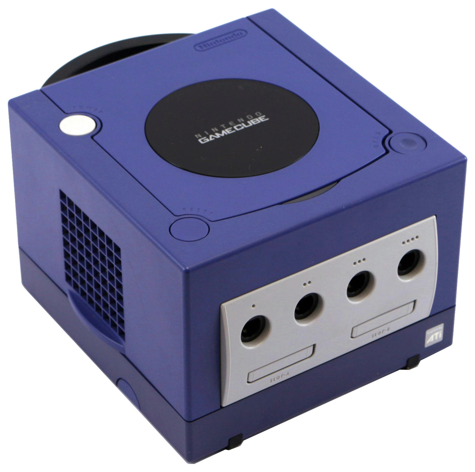
Nintendo GameCube Optical Drive Replacement Guide
Duration: 45 minutes
Steps: 16 Steps
Ready to dive into some GameCube magic? This guide shows you how to carefully take apart the GameCube Optical Drive Assembly so you can reach the Optical Drive and laser. These hardworking parts are the unsung heroes that read your game discs, making all those epic gaming moments possible. If the Optical Drive decides to stop spinning or the laser lens takes a hit, your console might have trouble reading discs. No worries though—sometimes, all it takes is replacing the part to get things rolling again. Since the GameCube’s a vintage gem, E-bay is a solid spot to hunt for replacement parts. Before you get started, you’ll need a 4.5 mm Gamebit screwdriver—this little gadget is a must-have for opening up certain Nintendo consoles and can be found online. Let’s get started!
Step 1


– Flip the Gamecube so the bottom side is up.
– Grab your 4.5 mm Gamebit screwdriver and unscrew all four screws.
Step 2


– Flip the GameCube so its belly is up, remove those screws, and gently separate the bottom shell from the top half—like opening a treasure chest of gaming goodness.
– Turn the GameCube around so its insides are facing up, giving you a clear view of its inner workings. Take a moment to appreciate the tech magic!
Step 3

– Give those clips on both sides of the back panel a gentle press to release them.
– Now, carefully lift off the back panel from the GameCube. You’ve got this!
Step 4

Heads up! There’s an orange-outlined ribbon cable still holding on. Let it chill—no need to yank it off.
– Pop off the controller ports at the front of the console with confidence.
– These ports are where the controllers connect to the system—they’re shaped like half circles. Easy peasy!
Step 5


This step might be optional based on what you’re aiming to achieve.
– Grab your trusty Phillips #2 screwdriver and unscrew the two fasteners holding the back of the control port in place.
– Gently separate the gray outer shell from the circuit board—take your time, no need to rush this delicate step!
Tools Used

Step 6


Heads up! Be careful not to detach the red and black cooling fan wire from the main unit – it’s boxed in orange for a reason!
– The left side of the unit is where the cooling fan and its trusty housing are chillin’.
– Gently unscrew the two screws keeping the cooling fan housing attached to the unit—take your time, no rush.
Step 7


– Pop out the four Phillips #1 screws holding down those trusty ground springs.
– Gently lift the ground springs off the main unit—they’ve done their job, and now they’re ready for a break!
Step 8


– The optical drive is snugly fastened to a sturdy metal plate.
– Grab your trusty Phillips #2 screwdriver and start unscrewing those twelve screws that are hanging out around the edge of the optical drive. You’ve got this!
Tools Used
Step 9


– Gently lift and detach the optical drive assembly from the GameCube base like you’re separating two besties after a long hug.
– The optical drive assembly is snugly connected to the motherboard below through a slot—don’t be shy, use a bit of steady pressure to free it, but keep it chill and careful.
– The metal plate and the optical drive itself are sticking together like peanut butter and jelly—they’ll stay attached for now.
Step 10


Handle the brown ribbon cable with care—let it chill in its spot and avoid messing with it.
– By now, your optical drive assembly should be chilling on its own, free from your GameCube.
– Flip that optical drive assembly over like it’s doing a somersault.
– With your trusty Phillips #1 screwdriver, remove the six screws holding things together.
– Gently lift and remove the metal plate like you’re unveiling a masterpiece.
Tools Used

Step 11


Hey, go easy there! Avoid tugging on the wire or yanking the connector off the board.
– Carefully tug on that blue wire until it pops free. No need for Hulk strength here—just a gentle pull will do the trick.
– Now for the brown cable: Give the black tab a little nudge away from the white plastic. Once the tension is gone, that brown cable will slide out as smooth as butter. Patience is key!
– Next up, grab your screwdriver and remove the four Phillips #1 screws holding the circuit board and optical drive assembly together. No sweat—it’s just unscrewing, after all.
– Oh, and don’t miss the sneaky fourth screw hiding behind the screwdriver in the third picture. It thinks it’s clever, but you’ve got this.
Step 12

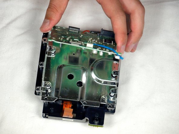

Hold up! Don’t mess with the red wire or that white ribbon cable linking the circuit board to the metal plate. Trust me, they’re better off staying connected.
– Pop open the tiny clip that’s keeping the board secured—it’s like a little treasure chest waiting to be opened!
– Carefully lift out the circuit board (yep, that’s the big green square). The pictures will guide you, so you’re in good hands!
– Spot the red wire—it’s your next clue.
– Handle the white ribbon cable gently, like you’re unwrapping a delicate gift. Easy does it!
Step 13


– Time to get this repair started! Use a flathead screwdriver to gently coax those four plastic clips into releasing the drive assembly – it’s like setting a tiny puzzle free!
– Now, carefully use your screwdriver as a little helper to loosen and release that last clip. You’re almost there!
Step 14
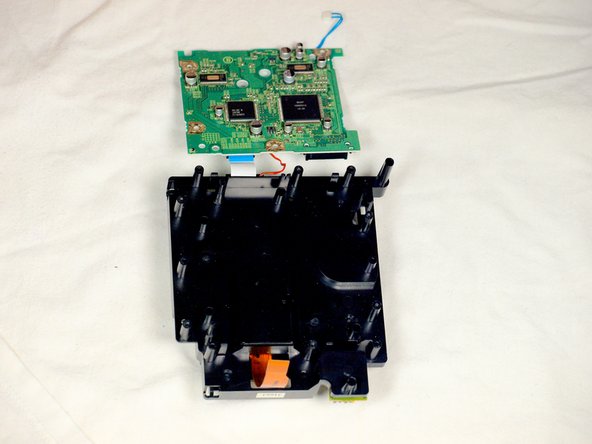


Watch out for the red wire and the white ribbon cable that are still connected to the two halves of the drive assembly. Let’s keep them intact and avoid any accidental snips!
– Carefully pop off that metal plate sitting on the drive assembly—it’s not as intimidating as it looks!
– Next, give the drive assembly a flip, turning both halves upside down like you’re showing off a magic trick.
Step 15


Watch out! Keep that red wire and white ribbon cable attached—don’t let them come loose!
– Grab a flathead screwdriver and pop off the two clips chillin’ on the back half of the drive assembly. Easy peasy!
– The last clip? No need to mess with it—just slide the top half of the drive assembly right off the bottom half. Smooth moves!
– Wrap it up by fully removing the top half of the drive assembly from the base. Almost there!
Step 16


– Put your device back together by following the steps in reverse—it’s like a fun puzzle in rewind!
– If you hit a snag or need extra help, you can always schedule a repair.
Tools Used
Success!