Nintendo GameCube Regional Modification Selector Switch
Duration: 45 minutes
Steps: 18 Steps
Got a cool Japanese import game for your GameCube, but it won’t play on your US console? No worries! We’ve got a simple mod to switch between NTSC-U and NTSC-J, and we’re here to walk you through it. Follow these easy steps to get playing in no time!
Step 1


– Flip the Gamecube so its bottom side is facing up.
– Grab your 4.5 mm Gamebit screwdriver and remove the four screws.
Step 2


– Time to get started! With the bottom side of the GameCube facing up and the screws removed, gently pull the outer shell away from the top half – it’s like opening a clamshell, but way more fun!
– Now, flip the GameCube over so the inside is facing upwards. You’re making great progress, and it’s about to get even more interesting!
Step 3

– Get ready to dive in – gently press down on the clips on either side of the back panel to release it.
– Time to take a peek inside – carefully remove the back panel from the GameCube to access the inner workings.
Step 4

Heads up! A ribbon cable (highlighted in orange) is still connected. Don’t worry, just leave it as is and don’t disconnect it.
– Pop off those controller ports at the front of the console with a little finesse.
– The controller ports are where your controllers connect to the console. They’re shaped like a half-circle, so you can’t miss ’em!
Step 5


This step might not be needed depending on what you’re trying to achieve. If you’re feeling stuck, you can always schedule a repair for some extra help.
– Grab a Phillips #2 screwdriver and unscrew the two screws on the back of the control port. Easy, right?
– Now, gently separate the gray outer casing from the circuit board. Take your time, no rush!
Step 6


Hey, make sure you don’t unplug that red and black cooling fan wire from the main unit. It’s the one boxed in orange.
– On the left side of the unit, you’ll find the cooling fan and its cozy little housing.
– Gently unscrew the two screws holding the fan housing in place—it’s like setting the fan free from its tiny home.
Step 7


– Unscrew those four Phillips #1 screws holding the ground springs in place. You’ve got this!
– Gently lift those ground springs out of the main unit. Take your time and be careful!
Step 8


– Alright, let’s do this! The optical drive is snugly attached to a metal plate—like peanut butter to jelly.
– Grab your trusty Phillips #2 screwdriver and unscrew all twelve screws lining the outer edge of the optical drive. Take your time and keep those screws in a safe spot!
Step 9


– Gently wiggle that optical drive assembly apart from the rest of your GameCube unit. It’s like a little dance between the two!
– The optical drive assembly is held tight to the motherboard below by a sneaky slot; you might need to apply a bit of gentle force to liberate it carefully.
– Don’t worry, the metal plate and the actual optical drive will stick together like best buds.
Step 10


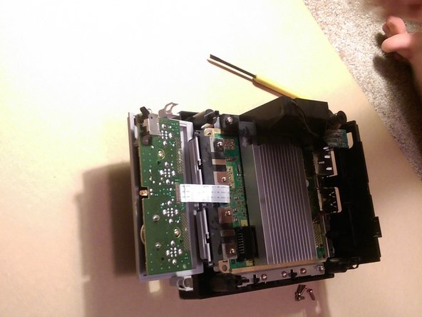
– You’re making great progress! Now that the Optical Drive Assembly is out of the way, take a look at your GameCube – it should look like this.
– Next, use a #1 Phillips screwdriver to remove the 6 screws (highlighted in orange) from the heat sink. You got this!
Step 11

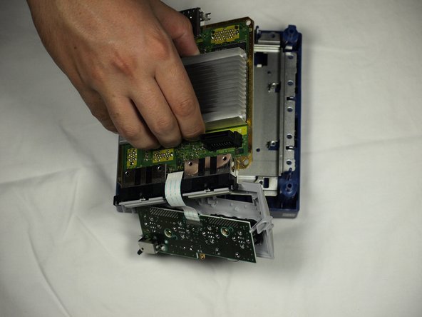
– Carefully lift the motherboard out of the base—like a pro handling treasure (see picture #2 for reference).
Step 12


Now’s the time to swap out that tired old motherboard for a shiny new one and bring your GameCube back to life!
– Gently unplug the ribbon cable that links the motherboard to the front panel. You’re doing great!
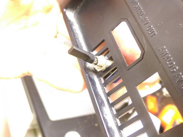
Step 13

– Find the R5 and R6 pads. They’re hanging out to the right of where the heat sink’s back middle screw used to be. If you’re working with an American system, the R5 pads will be all clear. On a Japanese console, you’ll find R6 is the one that’s empty.
Step 14

– Time to get your solder on! Solder those wires to either side of the empty pad – for American consoles, that’s R5, and for Japanese consoles, it’s R6.
– A quick note on region formats: US products rock the NTSC-U format, while Japanese products use NTSC-J. European models, on the other hand, use PAL – and if you’ve got one of those, this guide isn’t for you, sorry! If you need help, you can always schedule a repair with the pros at Salvation Repair.
Step 15

Hey, double-check those wires! They shouldn’t be playing tag with each other by soldering themselves together—it’s a one-way ticket to a permanent change.
When popping the heat sink back in place, I used a bit of electrical tape to keep the R5 connections from getting too cozy. Stay sharp!
Step 16
– Pop in the switch! In this example, we had to take out a small section of the vent to make room for a bigger switch. Make sure the switch is snug and secure, and double-check that it fits perfectly into the system before you move on.
Step 17

Grab a two pole double throw switch if you’re up for adding an indicator light.
– Grab some solder and connect the R pads to your switch. Hook one wire to any middle terminal, and pop the other wire onto the terminal right above or below it. Easy peasy!
Step 18

– Time to put everything back together! Make sure the new wires are tucked away neatly so they won’t get squished when you close things up. Keep them secure to avoid any accidental tugs.
– Follow the reassembly steps in reverse order—seriously, step by step. Otherwise, you might find yourself going through the process again. You’ve got this!
Success!