Nintendo Switch Front Frame Replacement Guide
Duration: 45 minutes
Steps: 71 Steps
This guide walks you through swapping out the front frame that wraps around the midframe and includes the display. Since guides sometimes mash steps into one sequence, you might see a step pop up more than once, or a photo might show parts on or off that don’t match what’s being done. No worries—just follow the written steps for what you’re doing and don’t sweat details like whether the battery’s hanging out or snugly in place!
Step 1


Before diving into this repair, double-check that your device is fully powered down—think of it as giving it a moment of zen before the operation.
– Give that little round button on the back of the Joy Con a solid press and hold it down like a champ.
– While keeping it pressed, smoothly slide the controller upward—like butter on a hot skillet. Keep it steady!
Step 2


Now, give the other Joy-Con the same TLC by repeating this process over there too. You’ve got this!
– Keep sliding that Joy Con up until it’s free from the console, just like a bird taking flight!
Step 3

As you tackle this repair, keep an eye on each screw and make sure it finds its way back to its original home. You’ve got this!
– Let’s get started! Use a Y00 screwdriver to carefully remove the four 6.3 mm-long screws that hold the rear panel in place. This is the first step in giving your device a brand new life!
Step 4


Keep those stubborn screws in check! Press down firmly, take it slow, and if they’re still playing hard to get, swap in a JIS 000 or PH 000 driver for some extra persuasion.
– Grab a JIS 000 driver or the Salvation Repair PH 000 driver and pop out these screws keeping the rear panel in place:
– One 2.5 mm-long screw at the top edge of the device
– Two 2.5 mm-long screws at the bottom edge of the device
Step 5


– Grab a JIS 000 screwdriver or an official PH 000 driver from iFixit and get ready to tackle those two 3.8 mm center screws on the sides of your device—one on each side. Let’s get those screws out and keep moving forward!
Step 6


If you’ve got a microSD card chilling in that slot, go ahead and pop it out now before moving on to the next step.
– Gently use your finger to pop up the kickstand on the back of the device—it’s like giving it a little friendly nudge!
Step 7

– Grab your trusty JIS 000 screwdriver or an official PH 000 driver, and get ready to remove that 1.6 mm screw from the kickstand well.
– Once you’ve got that screw out, close up the kickstand.
Step 8


The game card cartridge flap connects to the other side of the plastic shell, making it impossible to completely lift the rear panel if it’s still closed.
– Pop open the game card slot flap and get ready to move on.
– Carefully lift the rear panel from the bottom of the device and take it off. You’ve got this!
Step 9

– Grab a JIS 000 screwdriver or a Salvation Repair PH 000 driver and remove the 3.1 mm screw that’s holding down the microSD card reader in your device. You got this!
Step 10


– Grab hold of the microSD card reader with your fingers or a pair of tweezers and lift it straight up and away from the device. Boom, it’s out!
– When putting it back together, double-check that the press connector tucked under the foam pad is firmly snapped to the motherboard. If the foam pad gets in the way, feel free to move it aside before slotting the card reader back in.
Tools Used

Step 11

– Grab your trusty JIS 000 screwdriver or a PH 000 driver, and remove those six 3 mm screws holding the shield plate in place.
Step 12


If the foam isn’t peeling off like a charm, no need to wrestle with it! Gently try pulling it back from different angles to avoid any tears.
– Gently use your fingers or a trusty pair of tweezers to lift up the foam piece along the top edge of the device near the fan exhaust port.
Tools Used
Step 13


A thick pink thermal compound fills the gap between the shield plate and the copper heat sink beneath it. This keeps your Switch cool and happy, helping to avoid overheating.
You might feel a little resistance when separating things—don’t worry, that’s just the shield plate lightly sticking to the heat sink thanks to the thermal paste. Totally normal!
– Slide a spudger under the shield plate along the device’s edge with a gentle touch.
– Carefully pry it up to lift the shield plate off and set it aside.
– If you’re careful, you can totally reuse that pink thermal compound! Just keep it clean and ensure it makes good contact between the heat sink and the shield when you put everything back together.
– Need to swap it out instead? No worries! Check out our thermal paste guide to remove the old thermal compound and replace it with a suitable one, like K5 Pro, during reassembly.
Tools Used


Step 14


– Grab your trusty spudger and gently pop the battery connector straight up from its little home on the motherboard. Easy does it—no need to rush!
Tools Used
Step 15

– Grab yourself a JIS 000 screwdriver or the official PH 000 driver, and take out the three 3 mm screws holding the heat sink to the motherboard. You’ve got this!
Step 16
The foam is super sensitive and can rip pretty easily. Here’s a handy tip for peeling it off without a hitch:
Peel back just enough of the foam to make way for the fan—no need to go overboard!
– Gently peel off the two foam pieces that are stuck on both the heatsink and the fan. Take it easy; no need to rush!
– Slide the tip of a spudger underneath the edge of the foam where it’s not stuck to anything—like sneaking in a tiny spy.
– Use your finger to press down on the foam’s top to keep it steady. It’s teamwork, foam edition!
– Now, roll the spudger tip all the way to the other end, sliding under the foam as you go. Mission accomplished: the foam is free!
Tools Used
Step 17


You might notice a little pushback here, and that’s totally cool! It’s just the heat sink giving a friendly hug to the CPU thanks to some thermal paste. No worries, you’re doing great!
– Grab a spudger or just use your fingers to gently lift that heatsink off the motherboard. It’s like taking off a cozy blanket!
– Time to say goodbye to that old thermal paste! Use some high-concentration (90% or higher) isopropyl alcohol and a microfiber cloth to give the heat sink and CPU a good clean. Don’t forget to apply fresh thermal paste to the CPU before putting everything back together.
– Make sure to spread that new thermal paste on all the surfaces where it was before! This includes the area between the heatpipe and aluminum shield, which gives the Switch a little extra cooling love.
Tools Used

Step 18


– Carefully pry up the locking flap on the digitizer cable using an opening tool or your fingernail, making sure to take your time and be gentle to avoid any damage.
Step 19


Gently now—don’t jam that cable in! If it’s being stubborn, make sure the locking flap is upright, adjust the cable’s position, and give it another shot.
If your touchscreen’s acting up after the repair but your Game Card reader’s still kicking, double-check that this cable is snugly plugged in. If both the touchscreen and Game Card reader are on strike, swing over to the next step to inspect the Game Card connector.
– Grab your trusty tweezers and slide the digitizer cable out of its connector on the game card reader board—think smooth, horizontal moves here.
– When putting it back during reassembly, double-check that the ZIF connector’s locking flap is flipped up like a pro.
– With the cable lined up nice and parallel to the board, gently ease it into its connector—no need to rush, patience pays off!
Tools Used
Step 20


If your touch screen’s being stubborn or the game cards aren’t showing up after reassembly, there’s a chance this press connector isn’t quite snug enough. Gently disconnect it, take a deep breath, and give it another shot!
– Gently use the point of a spudger to pop the headphone jack and game card reader connector straight up to disconnect it from the motherboard.
– To re-attach press connectors like this one, line it up carefully and press down on one side until it clicks, then do the same on the other side. Avoid pressing down on the middle to prevent bending the pins and causing permanent damage.
Tools Used
Step 21

– Grab yourself a JIS 000 screwdriver or a PH 000 driver and unscrew the three 3.1 mm screws holding down the headphone jack and game card reader board. Keep your cool—you’ve got this!
Step 22


– Grab a trusty pair of tweezers or just your fingers and gently lift out the headphone jack bracket. You’ve got this!
Tools Used
Step 23


– Grab some tweezers or your fingers and carefully pluck out the headphone jack and game card reader board—it’s like removing a puzzle piece, but way more satisfying!
Tools Used
Step 24


– Grab your spudger, opening tool, or even just your fingernail, and gently pop up that tiny, hinged locking flap on the LCD ribbon cable’s ZIF connector. Easy does it!
Tools Used
Step 25


– Grab a trusty pair of tweezers and gently pull the ribbon cable straight out of its cozy connector on the motherboard. You’ve got this!
Tools Used
Step 26


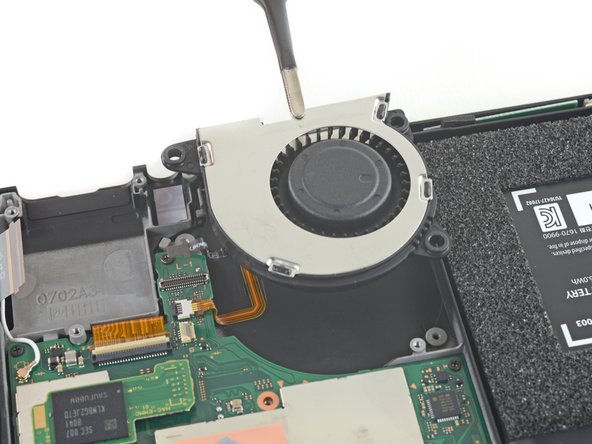
– Grab your trusty opening tool, spudger, or even your fingernail, and gently lift that little hinged locking flap on the fan cable ZIF connector. You’ve got this!
Tools Used
Step 27


– Grab your trusty tweezers and gently unplug the fan cable by pulling it straight out of its socket on the motherboard. Easy does it—precision is key here!
Tools Used
Step 28


– Grab an opening tool, spudger, or even just your trusty fingernail, and gently flip up the tiny hinged locking flap on the power and volume button ribbon cable ZIF connector. You got this!
Tools Used
Step 29


– Grab your trusty tweezers and gently slide that ribbon cable straight out of its connector on the motherboard like a pro.
Tools Used
Step 30


– Grab your spudger, opening tool, or even your trusty fingernail, and gently pop up the tiny hinged flap on the smaller LCD ribbon cable ZIF connector. Easy does it!
Tools Used
Step 31


– Grab those trusty tweezers and gently slide the ribbon cable straight out of its connector on the motherboard. Easy does it, you’re doing great!
Tools Used
Step 32


– Grab a spudger, an opening tool, or even just your trusty fingernail, and gently flip up that tiny hinged locking flap on the Joy Con sensor rail’s data cable ZIF connector. Easy does it!
Tools Used
Step 33


– Grab your trusty tweezers and gently tug on that ribbon cable, pulling it straight out of its cozy connector on the motherboard. You’ve got this!
Tools Used
Step 34


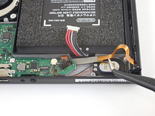
– Gently use the tip of a spudger to lift the black antenna cable straight up and out of its cozy little home on the motherboard.
Tools Used
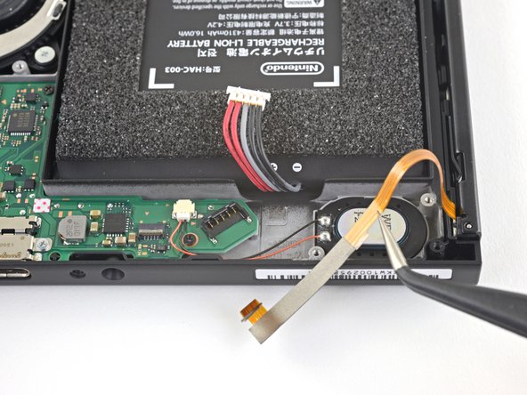
Step 35


– Gently use the tip of a spudger to nudge the white antenna cable straight up and out of its socket on the motherboard—easy does it!
Tools Used
Step 36


Handle the connector with care and avoid tugging on the speaker wires. They’re super delicate and can easily break off the connector.
– Grab those tweezers or your fingers and gently yank the right speaker connector straight out of its cozy little socket on the motherboard. Easy does it!
Tools Used
Step 37


Avoid tugging on the connector by the speaker wires—those little guys are super fragile and can snap faster than you’d think!
– Grab those tweezers or your trusty fingers and gently pull the left speaker connector straight out of its cozy little socket on the motherboard. Easy peasy!
Tools Used
Step 38


– Grab an opening tool, spudger, or even your fingernail and carefully pop up the tiny hinged locking flap on the Joy-Con sensor rail data cable’s ZIF connector. You’ve got this!
Tools Used
Step 39


– Take a pair of tweezers and gently slide the Joy Con rail data cable straight out from its connector on the motherboard. You’ve got this!
Tools Used
Step 40

– Grab a trusty JIS 000 screwdriver or a PH 000 driver and unscrew the following bad boys:
– Four 2.5 mm screws
– Two 3.1 mm screws
Step 41


– Grab your trusty spudger and slide it into the gap between the motherboard and the frame—like you’re unlocking a secret door.
– Gently lift the motherboard up, showing it some love, and carefully remove it from the frame. Take your time; no rush!
Tools Used
Step 42

– Grab your trusty JIS 000 screwdriver or a PH 000 driver, and unscrew those three 4.8 mm screws holding the fan like a champ.
Step 43

Match your shiny new part with the original. You might need to switch over any remaining bits (like those rubber bushings) to the new part before popping it in.
– Gently grab the fan with your trusty tweezers or fingers and lift it straight up to free it from the device. You’ve got this!
Tools Used
Step 44

These screws are on there pretty tight, so they might put up a bit of a fight when you try to remove them. To keep them from getting stripped, make sure to apply some solid downward pressure, take your time, and if they’re being stubborn, don’t hesitate to switch up your screwdriver. You’ve got this!
– Grab your trusty JIS 000 screwdriver or the official iFixit PH 000 driver and let’s get to work! Carefully unscrew those four 3.7 mm screws that are holding the right Joy Con rail snugly to the device’s frame. You’ve got this!
Step 45


Be careful not to let the rail’s data cable get caught on the device frame as you take it off.
– Gently slide off the right Joy-Con sensor rail—it’s like giving your console a little makeover!
Step 46


– Gently use your fingers or a trusty pair of tweezers to pop the battery connector up and slide it clear of the Joy Con rail’s data cable. No need to wrestle—just a smooth and steady move!
Tools Used
Step 47

– Gently use your fingers or a trusty pair of tweezers to lift the battery connector up and out of the way of the Joy Con rail’s data cable. You’ve got this!
Tools Used
Step 48

These screws can be a bit stubborn and might not want to budge. To avoid stripping them, press down firmly while working patiently. If they still refuse to come out, give a different screwdriver a shot.
– Grab your trusty JIS 000 screwdriver or the PH 000 driver, and unscrew those four 3.7 mm screws holding the left Joy Con rail to the device frame. You’ve got this—steady hands make light work!
Step 49


– Gently detach the left Joy Con sensor rail from your device. You’ve got this!
Step 50

– Grab the flat end of your spudger and gently pop up that taped-down power/volume ribbon cable like a pro!
Tools Used
Step 51


– Gently detach the power/volume board using a pair of blunt nose tweezers. You’ve got this!
Tools Used
Step 52

– Gently grab that rubber conductive pad with a pair of blunt nose tweezers and give it a little tug to pull it out. You’ve got this!
Tools Used
Step 53

– Use a pair of blunt nose tweezers to gently pull out the power and volume buttons.
Tools Used
Step 54


– Gently wiggle the black coax cable loose from the midframe—like you’re freeing a stubborn headphone cord from your pocket.
Step 55


– Keep tracing that wire like a pro, gently rerouting it as you go!
Step 56


– Gently lift the metal barrel that’s hugging the coax away from the midframe. Give it a little nudge and watch it pop up!
Step 57


– Carefully grab the WiFi antenna board with your trusty tweezers and gently lift it straight up to set it free.
Tools Used
Step 58

You can use a hair dryer, heat gun, or hot plate to help out, but keep it cool! Overheating can be a bummer for your device, especially for the display and internal battery, which are pretty sensitive to heat. Stay chill and be careful!
– Warm up an iOpener and press it against the bottom edge of the screen for about two minutes—this’ll help loosen up that stubborn adhesive.
Tools Used

Step 59


Depending on how long you’ve had your device, this might be a bit tricky. If you’re having a tough time, just crank up the heat a little more and give it another go!
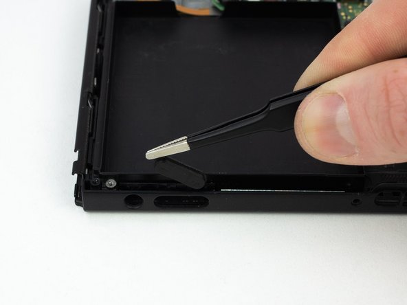
– Place a suction cup on the bottom-left corner of the screen.
– Give that suction cup a firm and steady pull to create a gap.
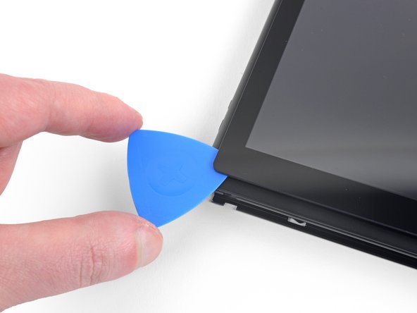
– Slide the tip of an opening pick into the gap, just about 5mm.
Step 60


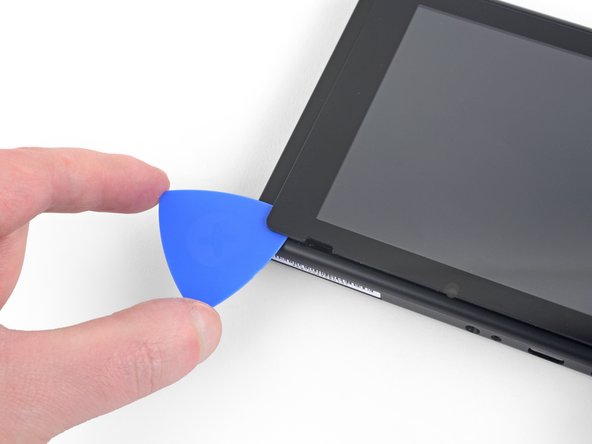
– Gently glide that opening pick along the bottom edge of your screen to cut through the adhesive like a pro.
– Keep the pick in place to stop the adhesive from sticking back to the frame. You’re doing great!
Step 61


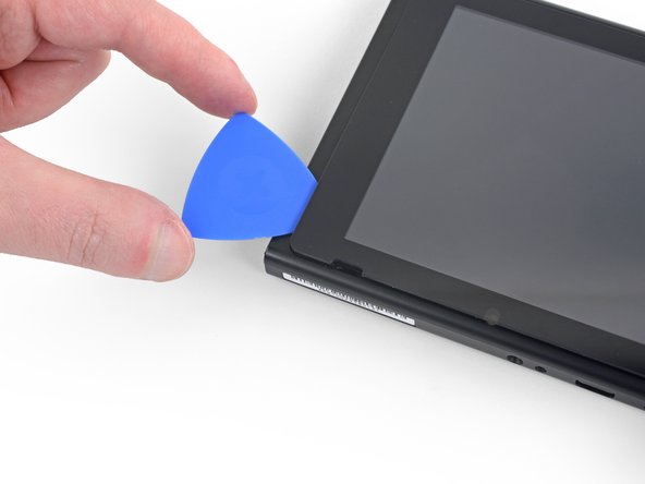
– Pop in a second opening pick right to the left of the first one.
– Slide that pick back towards the left side of your device.
– Keep that pick in place.
Step 62

– Warm up the left edge of the screen for about two minutes to loosen that stubborn adhesive—easy peasy, just like prepping for a sticker pull!
Step 63

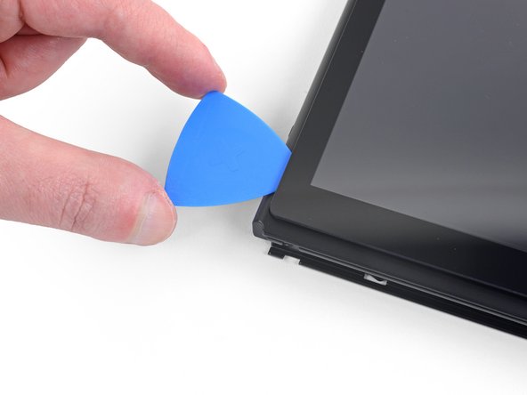
– Keep gliding that opening pick around the bottom-left corner to neatly slice through the adhesive.
Step 64


– Keep gliding that opening pick along the left edge of the screen to cut through the adhesive like a pro!
Step 65

– Warm up the top edge of the screen for a couple of minutes to loosen that stubborn adhesive—it’ll make things way easier.
Step 66

– Keep gliding that opening pick around the top-left corner of the screen to neatly cut through the adhesive. You’re doing great!
Step 67


– Now, keep sliding that opening pick along the top edge of the screen to carefully cut through the adhesive. You’re making great progress!
Step 68

– Get ready to loosen things up! Heat the right edge of the screen for about two minutes to soften the adhesive – this will make the next steps a whole lot easier.
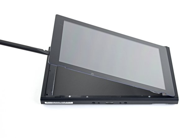
– Now it’s time to get a little leverage. Insert the flat end of a spudger into the gap along the left edge of the screen, and gently pry it open.
– Carefully lift the left edge of the screen, opening it like a book. Take your time and be gentle – you got this!
Tools Used
Step 69


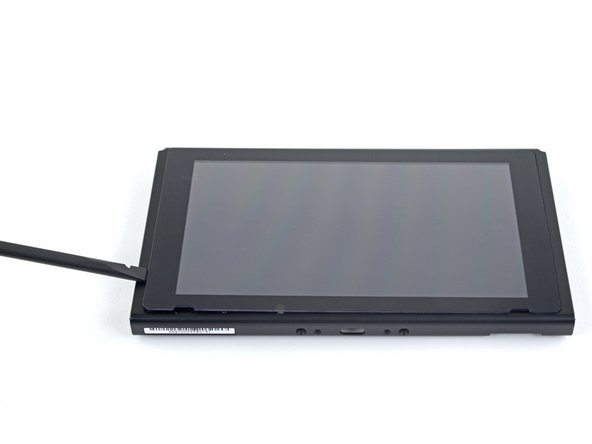
Be careful not to get those ribbon cables caught on the frame while you’re removing the screen—those little guys deserve some love and attention!
– Gently lift the right edge of the screen upward and away from the device, guiding the ribbon cables carefully through the frame as you go.
– If the screen adhesive is still holding strong, feel free to reuse it! If not, swap it out with some double-sided tape like Tesa tape to keep everything snug.
Step 70

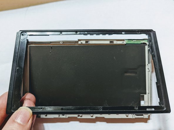
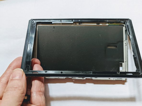
– Take out the four screws holding the front frame to the midframe.
Step 71

– Put your device back together by simply following the steps in reverse—it’s like pressing rewind on your repair adventure!
– If you need help, you can always schedule a repair.
Success!