Nintendo Switch Lite Screen Replacement Guide
Duration: 45 minutes
Steps: 68 Steps
Get ready to swap out that screen on your Nintendo Switch Lite! The screen is made up of the LCD and digitizer. If you’re just tackling the LCD, stick to this guide. If it’s the digitizer you’re after, follow this guide instead. Don’t forget, you’ll need some replacement adhesive to wrap things up nicely. And hey, while taking out the joysticks and buttons isn’t a must, it sure makes the whole process a breeze! If you need help, you can always schedule a repair.
Step 1

Before diving into this repair adventure, be sure to power down your device completely. Let’s keep things safe and sound!
As you dive into this repair, keep track of every screw like it’s your favorite playlist—make sure each one finds its way back to its original spot.
– Grab your trusty Y00 screwdriver and let’s dive in! Carefully take out those four screws that are holding the back panel in place, each one measuring 6.3 mm long. You’ve got this!
Step 2


To keep those pesky screws from getting stripped, press down firmly, take your time, and if they’re being stubborn, try switching up your screwdriver. You’ve got this!
– Grab a JIS 000 driver or a PH 000 driver—whichever you’ve got handy—and unscrew these little guys holding the back panel in place:
– Two 3.6 mm screws chillin’ at the top of the device
– Two 3.6 mm screws hangin’ out at the bottom of the device
Step 3


Careful now—don’t slide that tool in too deep, or the speaker module might not be too happy!
– Gently slide an opening tool into the left speaker grille at the bottom of your device.
– Give the opening tool a twist to pop those clips holding the back panel in place. You’re doing great!
Step 4


– Start by sliding the opening tool around the bottom-left corner to release the clips on the left side of the device. This is the first step in getting inside and making those repairs!
Step 5


Keep it cool—don’t push the opening tool too far to avoid messing with the speaker module.
– Gently slide an opening tool into the right speaker grille at the bottom of your device.
– Give the opening tool a little twist to pop those clips loose.
Step 6


– Time to get this device open! Slide and pry the opening tool around the bottom-right corner to release the clips on the right side – it’s like a little puzzle, and you’re the master solver!
Step 7


– Keep sliding and prying the opening tool along the gap at the top of the device to pop the clips free.
Step 8


– Flip the bottom edge of the back panel up like you’re opening your favorite book.
– Take off the back panel—easy peasy!
Step 9

– Grab your JIS 000 driver or your trusty Salvation Repair PH 000 driver and remove these four screws:
– Three 3.1 mm screws
– One 4.5 mm screw
Step 10


You might feel a little resistance here—that’s totally normal! The shield plate is just snugly attached to the heat sink with some thermal paste.
– Grab a spudger or just your trusty fingers and gently lift that shield plate right out of the device.
– Say goodbye to the shield plate as you remove it.
– Time for a little cleanup! Use some isopropyl alcohol and a microfiber cloth to wipe away the old thermal paste from both the shield plate and heat sink. Don’t forget to apply a fresh layer of thermal paste to the heat sink before putting everything back together!
Tools Used


Step 11


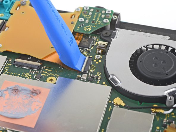
– Grab your trusty opening tool or your fingernail, and gently flip up the tiny hinged locking flap on the ZIF connector for the motherboard interconnect cable. It’s like opening a little treasure chest—go slow and steady to keep everything intact!
Step 12


Avoid using metal tweezers! They can accidentally short-circuit the ribbon cable or connector. Safer options are nylon-tipped or ceramic-tipped tweezers.
– Grab a trusty pair of tweezers and gently wiggle that interconnect cable free from its cozy spot in the motherboard connector. You’ve got this!
Tools Used

Step 13


– Gently nudge the battery connector straight up and out of its socket on the motherboard using the pointed end of a spudger. Stay cool—you’ve got this!
Tools Used
Step 14

Peel the foam back just enough so that it doesn’t obstruct the fan.
– Grab the flat end of a spudger or just use your fingers, and gently lift up the foam that’s lightly stuck to the fan. Easy does it!
Tools Used
Step 15

– Grab a trusty JIS 000 driver or a PH 000 driver, and unscrew those three little 3 mm screws holding the heat sink to the motherboard. Take it easy and keep those screws safe!
Step 16


You might encounter a little resistance here, and that’s totally okay! The heat sink is just a bit snug on the CPU thanks to the thermal paste. No worries, you’re doing great!
– Grab your trusty spudger or just use your fingers and gently lift the heatsink off the motherboard—say goodbye to that old thermal buddy.
– Wipe away the ancient thermal paste from the heatsink and CPU using isopropyl alcohol and a soft microfiber cloth. Once it’s squeaky clean, spread some fresh thermal paste on the CPU before putting everything back together.
Tools Used
Step 17

– Grab an opening tool or just use your fingernail to pop up the little, hinged locking flap on the game card reader cable’s ZIF connector.
Step 18

– Grab a JIS 000 driver or an official PH 000 driver and get to work! Remove the seven 3.1 mm screws holding the game card reader and headphone jack in place. It’s a quick step to free up some space for the next move!
Step 19


– Grab a trusty pair of tweezers or just your fingers, and gently lift the game card reader. Give it a little nudge to the left to slide that cable right out of its cozy connector.
– Now, go ahead and remove the game card reader along with the headphone jack. You’re doing great!
Tools Used
Step 20

– Grab a JIS 000 driver or a PH 000 driver, and unscrew the two 4.5 mm screws holding the right trigger button assembly to the motherboard. Easy peasy!
Step 21


– Gently pop out the right trigger button assembly.
Step 22

– Grab a pair of tweezers or just use your fingers to pop off the rubber pad from the right trigger button assembly—only if it didn’t stick to the button assembly already!
Tools Used
Step 23

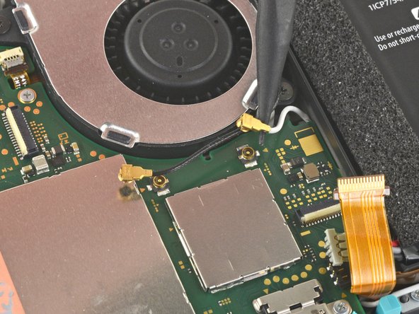

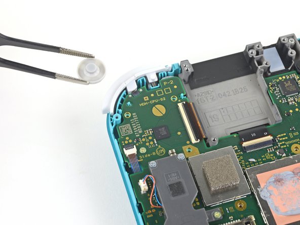
– Grab the pointy end of your trusty spudger and gently pop the black antenna cable straight up out of its little socket on the motherboard. Easy, right?
– Now, rinse and repeat with the white antenna cable—same moves, same style. You’ve got this!
Tools Used
Step 24

– Grab an opening tool or your fingernail and gently flip up the tiny, hinged locking flap on the ZIF connector for the fan cable—you’re almost there!
Step 25


– Grab a trusty pair of tweezers and gently wiggle the fan cable out of its cozy connector on the motherboard. You’ve got this!
Tools Used
Step 26


– Grab an opening tool or just your trusty fingernail to gently lift the tiny, hinged locking flap on the screen cable’s ZIF connector.
Step 27


– Grab your trusty tweezers and gently wiggle the screen cable free from its connector on the motherboard—nice and easy, like you’re coaxing a stubborn pickle out of a jar!
Tools Used
Step 28


– Grab an opening tool or your fingernail and gently flip up the tiny, hinged locking flap on the ZIF connector for the digitizer cable—easy does it!
Step 29


– Grab a pair of tweezers and gently slide the digitizer cable out of its connector on the motherboard. Take it easy, and be careful not to force it!
Tools Used
Step 30


– Grab an opening tool or your fingernail, and gently flip up the small, hinged locking flap on the right joystick cable’s ZIF connector. You’re doing great!
Step 31


– Grab your trusty tweezers and gently slide that right joystick cable right out of its snug spot on the motherboard.
Tools Used
Step 32

– Grab your trusty JIS 000 driver or the official iFixit PH 000 driver, and let’s tackle those six screws holding the motherboard in place:
– Three screws measuring 3.1 mm
– Three screws measuring 4.5 mm
Step 33

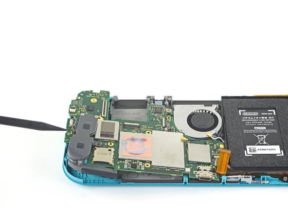

– Carefully wedge a spudger between the frame and motherboard, and gently lift the motherboard out of its snug little home.
– Now, go ahead and remove the motherboard assembly.
Tools Used
Step 34

– Grab a JIS 000 driver or a trusty PH 000 driver, and carefully unscrew the two 3.5 mm screws holding the joystick in place. You’ve got this!
Step 35


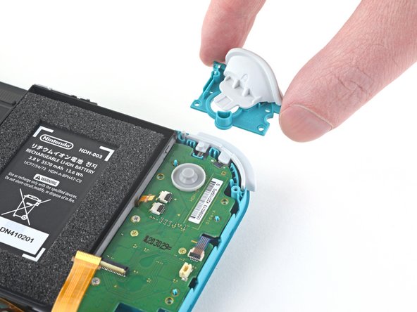
There’s a slim black gasket hugging the hole where the joystick peeks through the frame. When you’re pulling out the joystick, be gentle so you don’t mess up the gasket.
– Gently use your fingers to pop the joystick off. Take your time and give it a little wiggle to make sure it’s free.
Step 36


Handle those wires with care! Tugging on them might just send them flying off the connector. Keep it gentle, and you’ll be golden!
– Gently grab the left speaker cable with your tweezers or fingers and give it a little tug straight up to free it from its cozy spot on the daughterboard.
Tools Used
Step 37

– Grab a JIS 000 driver or an official PH 000 driver from iFixit and carefully unscrew the 4.5 mm screw that’s holding the left speaker module in place. You’ve got this!
Step 38


There’s a delicate ribbon cable hanging out underneath part of the speaker module. As you take out the speaker module, be careful not to get it caught on the cable.
– Gently grab the speaker module with your fingers and lift it out of its snug spot—it’s like giving it a little eviction notice!
Step 39


– Grab your trusty opening tool or just your fingernail, and gently lift that little hinged locking flap on the ZIF connector for the motherboard interconnect cable. You’ve got this!
Step 40


– Grab those tweezers and carefully slide the motherboard interconnect cable out from its connector on the daughterboard. You’ve got this!
Tools Used
Step 41


– Grab your trusty opening tool or just your fingernail, and gently lift up those little hinged locking flaps on the two ribbon cable ZIF connectors. You’ve got this!
Step 42


– Grab your trusty tweezers and gently nudge the daughterboard screen cable out of its connector on the motherboard. Take it slow—no rush, no fuss!
– Do the same thing for the volume buttons cable. You’re on a roll!
Tools Used
Step 43


– Grab a trusty pair of tweezers or just your fingers to gently pop off those volume buttons. You’ve got this!
Tools Used
Step 44


– Grab your opening tool (or just your trusty fingernail) and gently lift up the small hinged flap on the left joystick cable’s ZIF connector. It’s a simple move, but essential for moving on to the next step!
Step 45


– Grab some trusty tweezers and carefully wiggle the left joystick cable out of its snug spot on the daughterboard connector.
Tools Used
Step 46

– Grab a JIS 000 driver or an official iFixit PH 000 driver and get ready to tackle those two 4.5 mm screws holding the left trigger button assembly in place. You’ve got this!
Step 47

– Take off the left trigger button assembly with care.
Step 48

– Grab your trusty JIS 000 driver or a reliable PH 000 driver and let’s get those screws out. You’ll need to unscrew four in total:
– Two screws that are 4.5 mm long
– Two screws that are 6 mm long
Step 49


– Gently use your fingers to lift the daughterboard out of its snug little spot and set it free.
Step 50

– Grab your JIS 000 driver or the official PH 000 driver and get ready to tackle those two 3.5 mm screws holding down the left joystick. Let’s get those little guys out of there!
Step 51


You’ll find a thin black gasket around the hole where the joystick sticks out of the frame. Be gentle with it and try not to mess with this gasket as you remove the joystick.
– Grab your trusty spudger and gently nudge that joystick up and out of its cozy little spot.
– Now, with a little finesse, use your fingers to pop that joystick right out.
Tools Used
Step 52

– Grab your trusty JIS 000 driver or the official iFixit PH000 driver and let’s get those four screws out of the midframe assembly:
– Three tiny 2.5 mm screws
– One slightly bigger 6 mm screw
Step 53


– Grab your trusty spudger and gently coax the midframe assembly upward until you’ve got a good grip on it with your fingers.
– Once you’ve got a hold of it, lift the midframe assembly straight up to pop it out. Easy peasy!
Tools Used
Step 54


– Toss out any loose buttons still hanging around in the frame. Let’s keep it neat and tidy!
Step 55

When using a hair dryer, remember to give the screen a little love by heating it for just a few seconds at a time. Too much heat might make the plastic shell feel a bit too cozy and warp!
You could also grab a hair dryer and set it to Low heat—super easy and gets the job done like a charm!
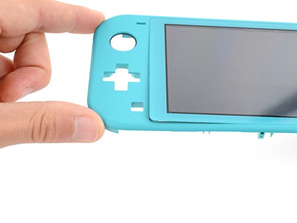
– Turn the frame so the screen is facing up.
– Warm up an iOpener and place it on the left side of the screen for two minutes.
Tools Used


Step 56
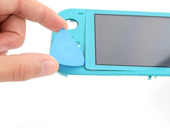

Keep your pick shallow—don’t go deeper than 3 mm or the screen might take it personally.
Struggling to get that gap started? Give your heated iOpener another two-minute session and give it another go.
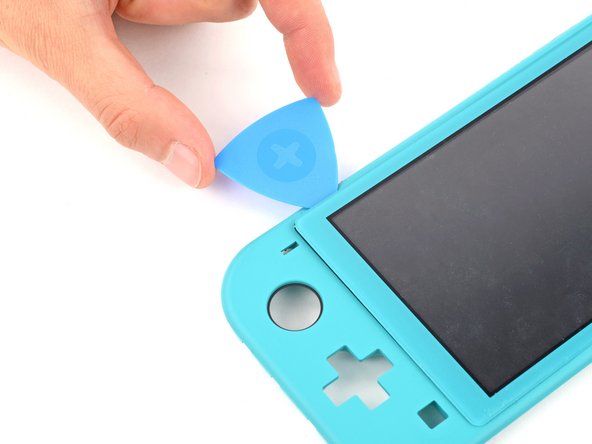
– Gently nudge the left side of the frame away from the screen to open up a little space in the bottom left corner.
– Slide an opening pick into that gap you’ve just created.
Tools Used
Step 57


While you’re working on this repair, remember to keep your pick to a maximum of 3 mm deep to keep that screen safe and sound!
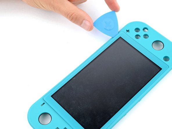
– Time to get this repair party started! Carefully guide the opening pick along the left edge – remember to take your time, we’ve got this!
– Now, leave that pick inserted in the top left corner – this will prevent the adhesive from sneaking back in and resealing, and that’s a win for us!
Step 58

Grab a hair dryer if you like, but keep it moving and don’t blast the screen for more than a few seconds at a time—gentle is the name of the game here!
– Place a warm iOpener on the top edge of your screen for about two minutes. This will help loosen things up, making the next step a breeze!
Tools Used
Step 59

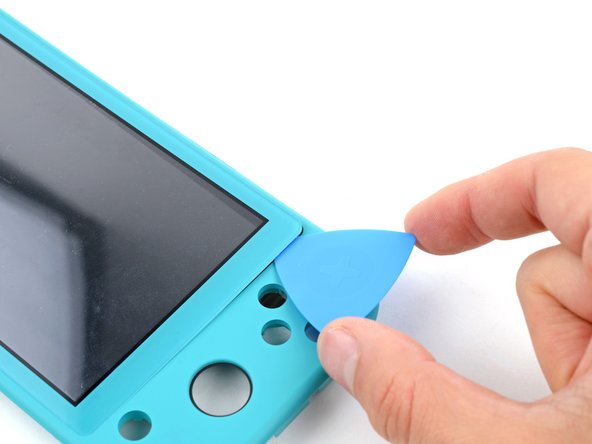
– Swing that opening pick around the top left corner like you’re tracing a smooth curve—you’re almost there!
Step 60

– Gently slide the opening pick along the top edge to get things started.
– Once you’re in, leave the opening pick in place at the top right corner to keep things steady.
Step 61

Feel free to grab a hair dryer, but keep it cool—don’t heat the screen for more than a few seconds at a time!
– Warm up that iOpener and give it a cozy two-minute hug on the right edge of the screen.
Tools Used
Step 62

– Gently guide the opening pick around the top right corner, giving it a little twist to work its magic.
Step 63


– Gently glide the opening pick down the right edge like you’re painting a masterpiece.
– Keep that opening pick snugly in the bottom right corner, just like a cozy blanket.
Step 64

A hair dryer can come in handy, just be sure to keep the heat on the screen to a minimum—only a few seconds at a time, okay?
– Warm up the bottom edge of the screen with a heated iOpener for a cozy two minutes.
Tools Used
Step 65


– Swing that opening pick gently around the bottom right corner like you’re tracing a smile.
Step 66


– Gently glide the opening pick along the bottom edge like you’re spreading butter on toast.
Step 67


– Carefully grasp the frame of the device and gently push up on the underside of the screen’s left edge. This will help loosen the adhesive holding it in place. Work patiently and take your time to avoid causing any damage to the device.
Step 68


The digitizer cables are like clingy friends, making it tough for the screen to pop right off the frame. No worries, though!
If the screen is still playing hard to get, grab an opening pick and gently slide it around the edges. Give it another go!
– Check out your new part compared to the original—there might be a few bits left to swap over or a sticky backing to peel off before it’s ready to go.
– When putting your device back together, just follow the steps in reverse. You’ve got this!
– Got some old parts or broken bits? Drop them off at an R2 or e-Stewards certified recycler—they’ll handle it responsibly.
– Ran into a hiccup? Give troubleshooting another shot, or if it’s still a puzzle, you can always schedule a repair.
– If you nailed the repair, congrats—your device is back in action!
Success!