Nvidia Shield Tablet K1 Micro USB Port Replacement
Duration: 45 minutes
Steps: 20 Steps
Let’s get that tablet charged up again! The Micro USB Port is where the magic happens, and if it’s damaged, you might find it’s a bit wobbly or just not playing nice with your charging cable. Time to give it some TLC!
Step 1

– Let’s get started! Begin by using the blue plastic opening tool at the Micro SD Card Slot. Gently work your way around the edges, applying light pressure to carefully lift the panel upwards. Take your time and be patient, you’ve got this!
Step 2


– Get ready to pop that back panel off! There are some sneaky clips keeping it secure, so give it a little nudge to start lifting it away.
– Keep that momentum going and gently lift up the panel all around the tablet’s edges.
– Once you’ve successfully unlatched all the clips, carefully take off the back panel. You’ve got this!
Step 3


The battery is stuck down pretty good, so you’ll need to put some muscle into it. Just keep a steady hand and be mindful of the surrounding parts—gentle persistence wins the day!
– Grab your trusty blue plastic opening tool, and gently slide its edge under the battery like a pro—just like in the photo. Easy does it!
Step 4


– Once you’ve slid the blue plastic opening tool underneath the battery, gently work it around the edges, just like you would when prying off the back panel. Take your time, and remember, patience makes for a smooth repair.
Step 5

The battery has four wires that keep it connected to the device. Handle these wires with care so they stay safe while you’re removing the battery.
– As soon as the battery feels like it’s ready to be freed, grab that trusty blue plastic opening tool and gently pry the battery away from the device. You’ve got this!
Step 6


The battery wires are snugly soldered onto the motherboard—precision is key here! If you’re feeling unsure about your soldering game, no worries. Check out the soldering techniques guide for some handy tips to level up your skills.
– If your device’s wiring doesn’t match up perfectly with these pictures, grab your phone or a notebook and jot down which color wire connects to which contact on the motherboard before unplugging anything. (Trust me, you don’t want a mismatched battery causing electrical chaos—it could fry your tablet for good!)
– Fire up your soldering iron and carefully desolder the four wires from the motherboard. Take your time—patience is key!
– Once those wires are free, congrats! The battery is officially ready to be removed from your device. You’re one step closer to victory!
Tools Used

Step 7

– Time to get disconnected! Use those handy angled tweezers to carefully pull the black power cable out of its slot on the mother board. You should feel it pop up easily when it’s free.
– Now, let’s make sure we’re disconnecting the right cables – there are three of them, so take a close look and double-check your work. We’ve got this!
Tools Used

Step 8

Screw specs: short black screw, 20 mm long and 30 mm wide. Think of it as the chill little sidekick holding things together.
– Let’s get started! Remove the screw next to the WIFI Antenna using your trusty J000 Philips head screwdriver. Take your time and make sure it’s nice and loose.
Step 9

– Let’s get started! Use those handy angled tweezers to carefully begin removing the antenna from your device.
Tools Used
Step 10


– Grab those trusty tweezers! The black plastic part of the antenna is chillin’ on a copper-colored film—give it a gentle tug upwards.
– Boom, the antenna is officially liberated from the device. Smooth move!
Tools Used
Step 11


Hey, be gentle when peeling off those two pieces of tape – there are wires hiding underneath! Lift with care to avoid accidentally yanking them out.
– Grab your trusty black plastic spudger and gently lift the tape with your fingers while using the tool to keep the wires in place. Take your time and stay steady – you’re doing great!
Tools Used

Step 12


The audio input film is tucked away beneath that foam piece and it’s a bit delicate! So, take your time and be gentle when you lift it out.
No need to peel off the foam completely—just loosen it up enough to let the audio input film slide out nice and easy.
– Gently lift the black foam piece near the WIFI antenna. This will reveal the audio input film, just waiting for your attention!
Step 13


– Let’s get those speakers singing again! Start by carefully removing the audio input films from their ZIF connectors – you’ll recognize them as the super-thin ribbons with orange stripes.
– Time to set those films free! Pull up the white latch on the ZIF connector, and gently pull out the film with some tweezers. Easy peasy!
– Repeat the process for the second speaker, and you’ll be rocking out in no time. If you need help, you can always schedule a repair
Tools Used
Step 14


– Unplug those power cables connecting the speakers to the battery. Look for the black wires with shiny gold tips—they’re the ones you’re after.
– Grab your trusty tweezers and gently lift those cables out of their spots. They should come off pretty easily, like magic.
– There are three of these black wires in total, but only two are for the speakers. Follow the wire paths to double-check which ones are connected to the speaker terminals!
Tools Used
Step 15

Each screw measures approximately 30 mm in length and 30 mm in diameter.
– Set the speakers free by unscrewing them using a J000 Phillips-head screwdriver. Easy peasy, right?
Step 16


– Gently use your tweezers or fingers to lift the remaining black wires off the motherboard. It’s a simple step, just make sure you handle them with care, so nothing gets damaged.
Tools Used
Step 17


– Unscrew those pesky remaining screws that are keeping the motherboard snug as a bug in a rug.
– Screw details: 5 short black screws, each a speedy 20mm in length and 30mm in diameter.
– Screw details: 3 long black screws, measuring a robust 40mm in length and 20mm in diameter.
Step 18


– Gently pinch the brown ZIF (Zero Insertion Force) tab with your fingers and pull it outward to disconnect. It should come apart easily.
– You’ll see an orange chip snugly connected to a white ZIF (Zero Insertion Force). Carefully remove it using your fingers or a pair of tweezers.
Tools Used
Step 19
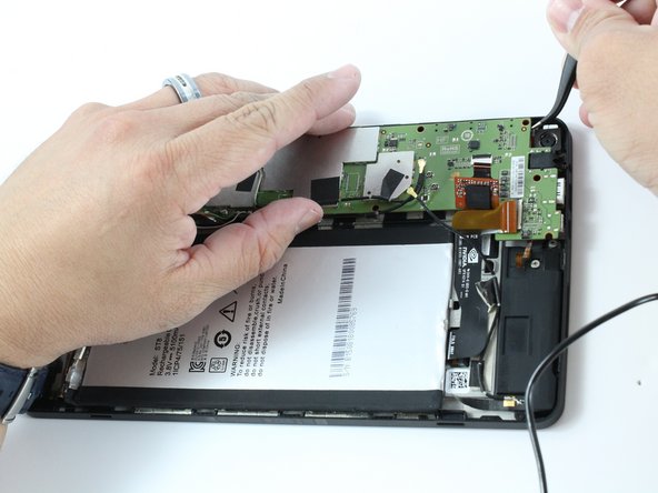


Heads up! As you lift the motherboard near the edge by the rear-facing camera, there’s a sneaky copper cable hiding underneath it. Handle it with care!
– Time to get a little gentle with your device! Use your trusty tweezers to carefully lift around the edges and loosen the motherboard.
– Almost there! Before you fully remove the motherboard, use your tweezers to disconnect the rear camera’s copper cable from the motherboard. Easy does it!
Tools Used
Step 20


– Pop everything back together by working through the steps in reverse—it’s like rewinding your repair adventure!
– If you hit a snag or need an extra hand, you can always schedule a repair.
Tools Used
Success!