OnHub Teardown
Duration: 45 minutes
Steps: 13 Steps
We’re diving into a new router that’s ready to shake up the home-networking game. With a clean design, a bit of a splurge in the price department, and plenty of unique features, this router is definitely worth a closer look. It’s teardown time! Need a hand? If things get tricky, don’t hesitate to schedule a repair.
Step 1


– Get ready to explore the ins and outs of this device with a little tech swagger. We’ll walk through the key specs that make it a powerhouse: a speedy dual-core 1.4 GHz processor, 4 GB of flash storage for your files, support for IEEE 802.11 b/g/n/ac Wi-Fi standards, and a dual-band 2.4 GHz and 5 GHz antenna array equipped with 12 antennas for solid signal strength. Plus, it features a congestion-sensing radio and antenna to keep your connection smooth, along with a USB 3.0 port and Bluetooth 4.0 for versatile connectivity, all backed by 1 GB of DDR3L RAM to keep things running effortlessly. If you need a hand with any tricky steps, you can always schedule a repair.
Step 2


This LED ring will change colors based on what state the OnHub is in. Blue means you’re ready to begin setup. Orange is for, “Oh snap, something is wrong.” Teal means you’re good to go!
– No blinking router lights here; let’s hope the constant status light isn’t blinding in the dark (it’s not).
– We also spy a small cutaway on the bottom of the cowling for the cabling.
– This mysterious anomaly in the speaker grille is probably an ambient light sensor enabling dimming.
– A novel idea for cable management, but not great for ease-of-access. You’ve got to twist the cowling off to plug anything in.
Step 3


The TP-Link expert gives this product a thumbs up. We’ll see what he thinks once the ASUS OnHub joins the lineup later this year. Stay tuned!
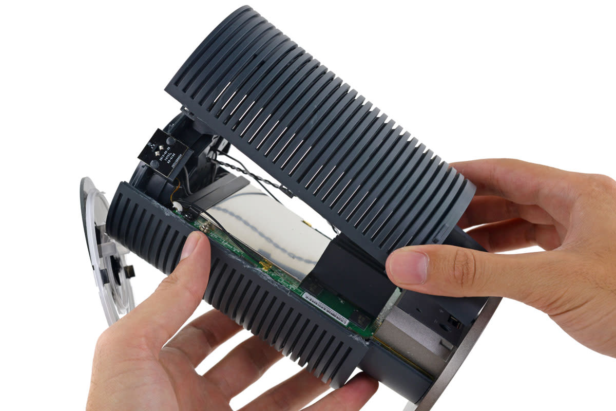
– Thankfully, the outer shell is super easy to remove with just a quick twist. No cables can be connected until that shield is off, so it’s a good thing it’s simple.
– The grooves on the inside of the barrel shell probably help with airflow, since this tower doesn’t have a fan to keep things cool.
– Peek under the hood and we find the real branding. This model was made with the first version of OnHub, courtesy of a partnership with TP-Link.
– We also get a sneak peek at some of the internal components. Could that be an antenna? Our curiosity is definitely piqued.
Step 4


Well, it looks like this spot isn’t the right one for entry either! We ended up snapping a few clips along the way. Oops!
– The rubbery foot looks like a good spot to hide some screws. Sure enough, we pop a few out. Did that really do the trick? Not quite.
– After dealing with some resistance, we head for the tempting seam along the sides of the tower.
– This thing still won’t open… If you need help, you can always schedule a repair.
Step 5

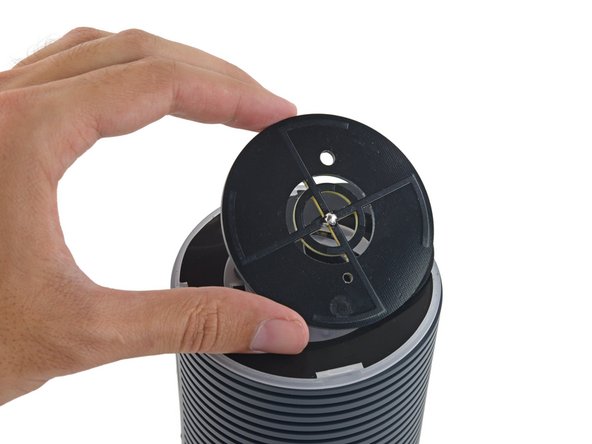
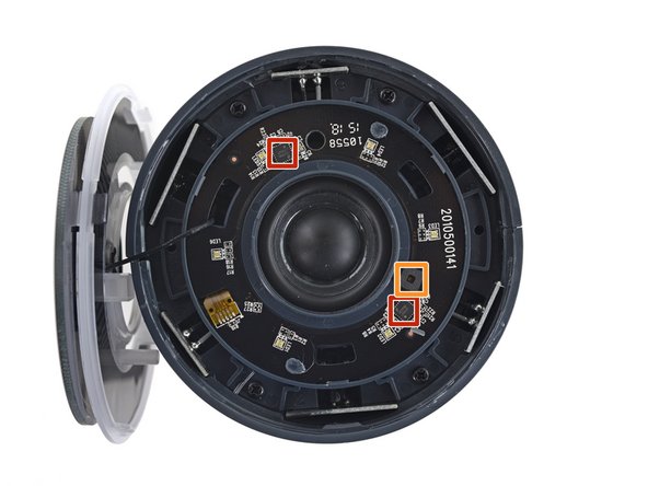
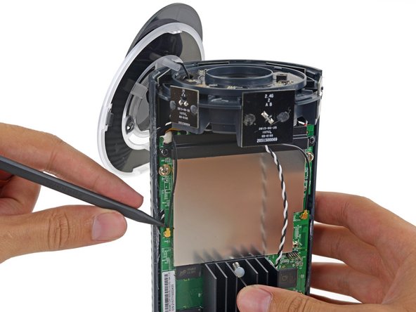
We really wish this came with a guide—this cap is probably the first thing that should go!
– Let’s revisit what we thought was a sturdy top—turns out, that was the secret sauce all along. Carefully pop off this can of worms, revealing our first clue: the infamous congestion-sensing antenna. We can’t quite detach it yet, so gently let it dangle aside to give us a clear view of the LED board with some control hardware, including the National Semiconductor LP5523 programmable 9-output LED driver and the ambient light sensor. Take your time, and if you need extra help, you can always schedule a repair.
Step 6

– With the top panel out of the way, you’ll spot a few screws waiting for your attention.
– Now, with the casing split, you’re getting your first look at the OnHub’s sleek, antenna-packed interior.
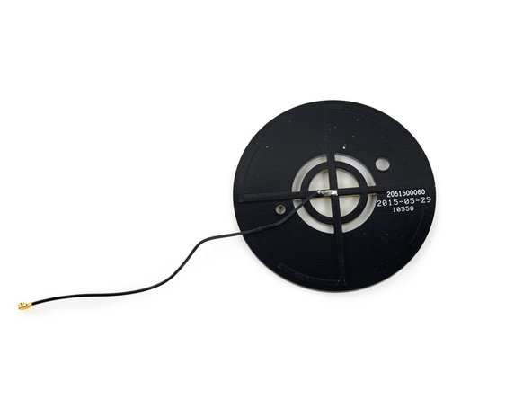
– That funky disk antenna on top, which was hard at work monitoring network congestion, is finally free to make its exit from the OnHub.
– Looks like this OnHub is keeping its Wi-Fi on point with a bullseye-style antenna to make sure your connection stays solid.
Step 7
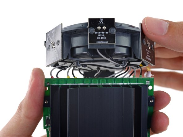

– Check out the top of the device—there are 12 cables lined up: six for 2.4GHz and six for 5GHz antennas. You’ll also spot a congestion antenna running along one side, and a lone coax cable on the other.
– Once the second half of the outer shell comes off, you’ll find a double-diamond antenna setup that’s definitely worth a second look. We’ll dig into that unique design soon.
– The antenna array here is a sight to behold, with all those leads twisting around like a sci-fi creature’s tentacles.
– There’s some color coding on the antenna leads, which might come in handy during reassembly, but the board itself keeps its secrets for now.
Step 8


The hexagonal speaker enclosure kind of looks like the emblem of the Galactic Empire. A little sci-fi fun for your repair journey!
OnHub gets creative with pairing—using a loud tone alongside ultrasonic signals to set up Android devices with the companion app. Who knows, maybe dance tracks are next on the playlist?
– Once you’ve unplugged a dozen connectors, the antenna assembly is free from the motherboard. Victory!
– Check out that massive speaker—why does this router need a 3-watt sound system? Talk about making a statement!
Step 9
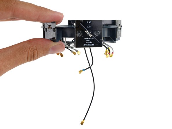

The six PCBs each come with a pair of antennas. The smaller ones are 5 GHz, while the larger ones are 2.4 GHz. They alternate around, so each pair of antennas is set 120° apart from the other two pairs using the same frequency. Pretty clever, right?
– Pop those last antenna connectors off with a quick flick of your spudger. You might feel like you’re unlocking a tiny portal to another dimension—or maybe just freeing the antenna array.
– Whoever designed these arrow-shaped antennas definitely had some style points in mind. Looking sharp!
– That one super-long cable snakes a bit farther down the motherboard and plugs in right next to the ZigBee co-processor—getting ready for 802.15.4 (coming soon).
Tools Used

Step 10
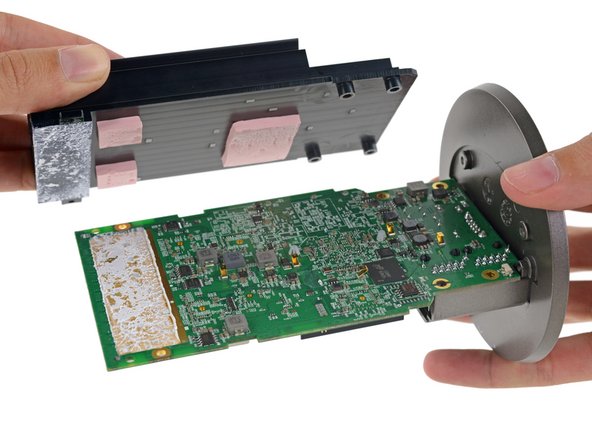

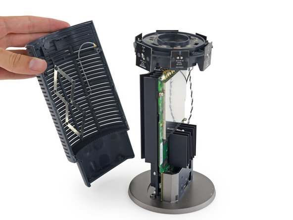
– Remember that diamond-shaped antenna from a few steps back? Well, it’s actually the directional antenna, which helps boost your signal in a specific direction – pretty handy!
– So far, the components in this device have been pretty large, and the heat sink is no exception. When you pry it up, you’ll find some equally impressive thermal pads underneath.
– It looks like the heat sink is connected to the motherboard, which is where the real heat-generating components are located.
– Now, let’s remove the plastic base and port cover – it should slide right off. Once that’s done, the motherboard will be free!
– The heat sink also acts as a reflector dish, helping to push that extra bit of Wi-Fi signal to the far corners of your house, where you need it most.
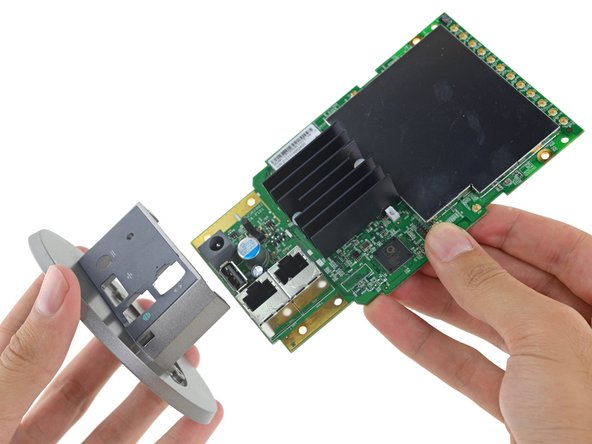
Step 11

– Now that the heat sink is off and the chips are out in the open, it’s time to check out the tech goodies inside:
– Qualcomm Atheros IPQ8064 quad-core Internet Processor, rocking 2 Krait 300 CPUs at 1.4 GHz
– Micron MT41K256M16HA-125:E 4 Gb DDR3L SDRAM for speedy memory action
– Qualcomm Atheros QCA8337-AL3C—your seven-port gigabit Ethernet switch
– Qualcomm Atheros QCA9882-BR4A Wi-Fi SoC supporting 802.11ac/a/b/g/n standards
– Qualcomm Atheros QCA9880-BR4A dual-band WLAN SoC, featuring 3×3 MIMO and all the 802.11 flavors
– Silicon Labs EM3581 SOC, which handles ZigBee networking
– Skyworks SKY66109-11, a 2.4 GHz ZigBee/Smart Energy front-end module
Step 12


– Hold on, there’s more to explore! Here’s a quick rundown of some key components you might encounter: the Skyworks SE2623L-R 2.4 GHz WLAN power amplifier, the Skyworks SKY85405-11 802.11ac 5 GHz WLAN power amplifier, the Atheros AR3012-BL3D Bluetooth radio, a Bluetooth antenna, Micron’s MTFC4GACAAAM-1M WT 4 GB NAND flash, Micron’s N25Q064A 64 Mb SPI flash, and the Infineon SLB9615 Trusted Platform Module. As you work through the repair, keep these parts in mind—they’re essential for wireless connectivity and storage. Remember, if you ever need expert help, you can always schedule a repair with Salvation Repair for those tricky steps.
Step 13

– OnHub Repairability Score: 4 out of 10 (10 is easiest to repair). It’s not the simplest, but it’s not impossible!
– The speaker? Yup, you can swap it out when it’s time to upgrade or replace.
– The device is mostly held together by clips – much better than sticky glue, but do take care as they can snap during disassembly.
– All the ports live on one board. So, if your USB port’s being a little loose, be prepared for a soldering repair.
– Tiny antenna connectors are delicate, so handle them with extra care to avoid any breakage during the process.
– This device is on the trickier side of things. No official repair docs make it a bit of a puzzle. If you get stuck, you can always schedule a repair.
Success!