RCA Radio Alarm Clock Teardown
Duration: 45 minutes
Steps: 20 Steps
Ready to peek inside your RCA Radio Alarm Clock? In this guide, we’ll walk you through taking it apart and checking out what’s going on under the hood. No smashing or bashing required—just a straightforward teardown to satisfy your curiosity or help with repairs.
Step 1


– Meet your RCA RP3715A Radio Alarm Clock!
– What’s cool about it: Giant green digital numbers so you can see the time from across the room, two separate alarms for those who like living on the edge, a built-in AM/FM radio, classic tuner and volume dials, voice readout when you want to hear the time, and an auto-dimming display that chills out in low light.
– Button roll call: ON/OFF, WAKE 1, CANCEL, WAKE 2, REV, FWD, NAP, SLEEP, and SNOOZE. Each one ready for action!
Step 2


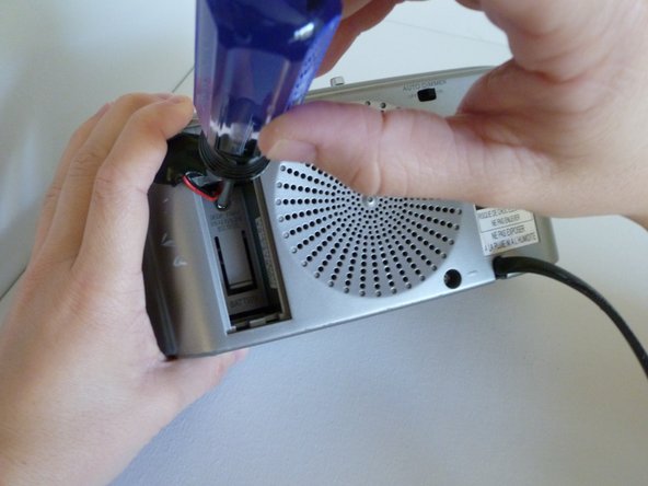
Keep in mind: In this particular case, there might not be a battery involved. A battery is only necessary if you’re planning to use the device without being plugged in. If you run into any issues, remember you can always schedule a repair for expert help.
– Get ready to open up the clock: first, unplug it from the power source. Then, flip it over and locate the battery compartment on the back. Press down on the top tab of the clear plastic door and gently pull it off. Next, disconnect the battery by pulling it away from the leads. Set the battery aside and you’re all set to move forward. If you need a hand, you can always schedule a repair.
Step 3


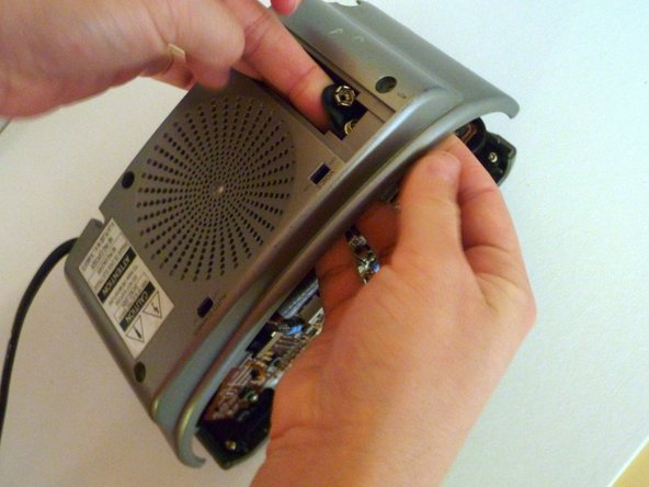
– Let’s get those back panel screws out of the way:
– First, gently lay your clock face-down—don’t worry, it won’t mind.
– There are six screws hanging out back there, each with a tiny arrow pointing at them on the grey panel:
– One’s hiding inside the battery compartment.
– Three are chilling around the speaker area.
– And two longer screws are posted up at the bottom corners—left and right—of the panel.
Step 4
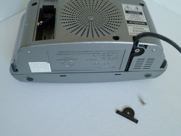

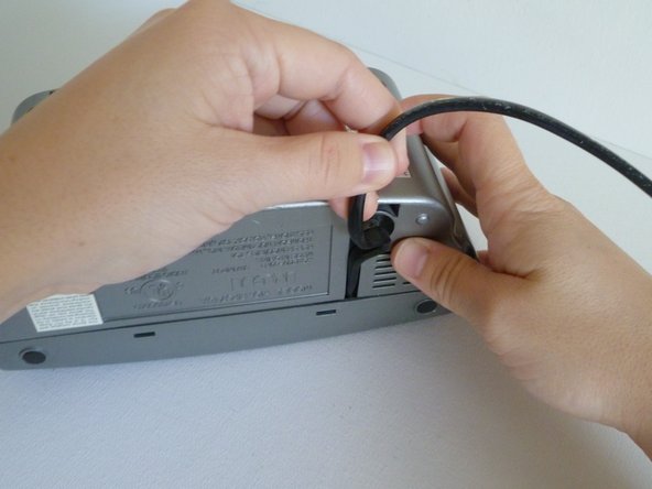
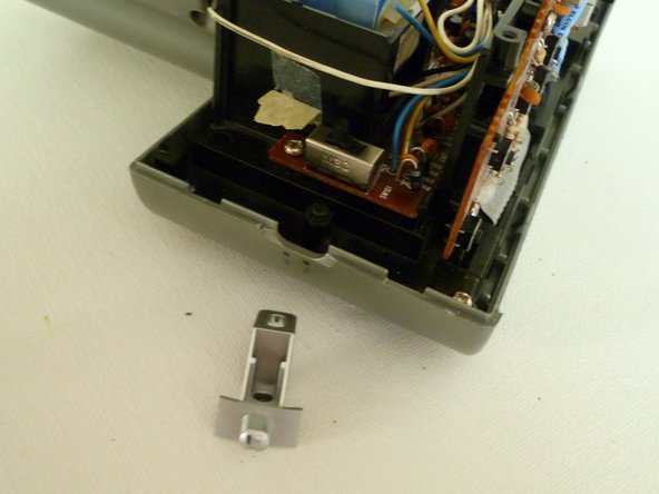
– Time to loosen up that power cable strain relief! First, take out the screw and metal bracket that’s sitting snug over the power cord on the base of the clock.
– Now, gently wiggle the power cord and pull it free from its little slot. You’ve got this!
Step 5


If those tabs are being stubborn and your fingers just can’t get the job done, grab a flathead screwdriver to help you out. It’ll make things much easier!
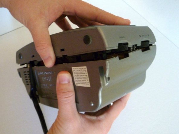
– Let’s get that Top Panel and Control Buttons off, shall we? First, flip your clock over and give those two plastic release tabs a gentle press at the seam where the front and back panels meet.
– If you encounter a little resistance, no worries! Just take a peek at the seven internal release tabs. Usually, they play nice and your clock will pop apart without a fuss. If you find one being a tad stubborn, a flathead screwdriver can help you coax it loose. Here’s where to find those sneaky tabs:
– Two are hanging out right above and below the CANCEL button on the top panel.
– Two more are nestled above and below the FWD button on the top panel.
– Another pair is sitting pretty above and below the AM/FM switch on the side of the clock.
– And last but not least, there’s one tucked between the TUNING and VOLUME dial on the opposite side of the clock.
Step 6

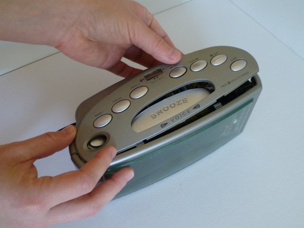
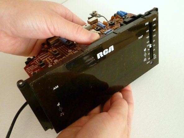
Just a heads-up: The SNOOZE and ON/OFF buttons aren’t actually connected to the top panel, so they might just decide to make a quick getaway. Keep an eye on them!
– Take off the Top Panel and Buttons:
– Set the clock upright and ready for action.
– Gently slide the top panel away from the release tabs, then lift it right off.
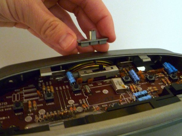
– Pop off the grey plastic cover from the WAKE1/WAKE2 switch on the top logic board.
Step 7

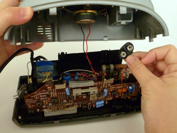
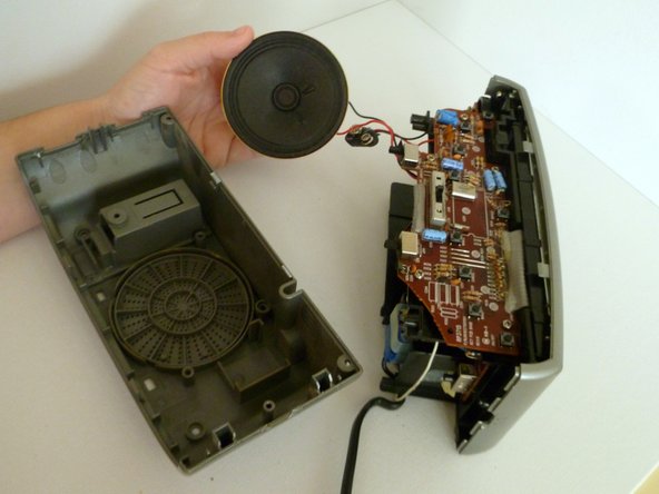
Take it easy! The unit won’t come fully apart just yet—there’s still a sneaky little speaker holding the back panel to the clock’s main logic board.
– Take off the Back Panel: Carefully lay your device down and gently lift off the back panel. Don’t rush, take it slow!
– Get those Battery Leads: Now, carefully pull the battery leads through the little hole in the back of the compartment. Steady hands make all the difference!
Step 8

– Gently pop off the grey plastic AM/FM switch button on the left side of the clock. It should come off easily and almost fall out on its own.
Step 9

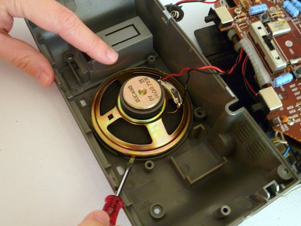
Note: The speaker is lightly glued in place.
– Take out the Speaker:
– Unscrew the two screws and remove the metal brackets that are holding the speaker to the back panel.
– Now, using a flathead screwdriver, carefully pop the speaker off the back panel.
– The back panel is free and clear—you’re making great progress!
Step 10

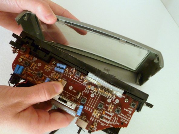
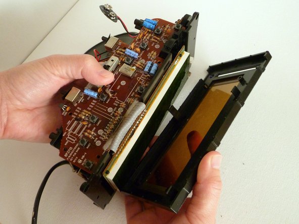
– Take off the Bezel Panel and Display Window:
– Start by unscrewing the two screws holding the front bezel panel in place. No need to rush here!
– Now, gently pry off the front grey bezel panel, and separate the clear plastic display window. It should come off smoothly, just take your time.
Step 11
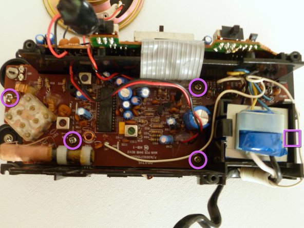

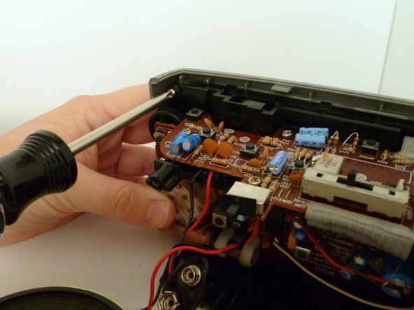
Heads up! There’s a sneaky screw hiding on the outer edge of the power supply, right by the main logic board. Look for it in the purple box – it’s easy to miss, but once you spot it, you’re good to go!
– Unscrew the ten screws holding down the logic boards.
– Place the clock on its base to keep it stable.
– Remove the five screws securing the top logic board.
– Flip the clock over gently onto its face.
– Take out the five screws on the main logic board.
Step 12

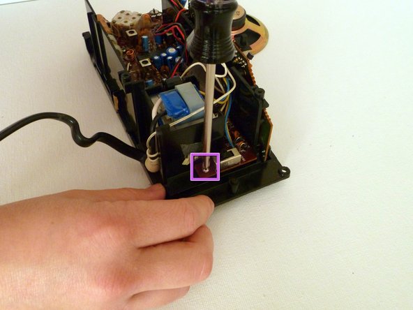
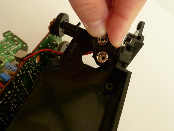
Gently lift the logic board next to the black tuning dial to ease it out.
– Take out the Tuning Dial: place the clock face-down to get started.
– Loosen the black tuning dial located just below the main logic board and take it out.
– Removing this frees up the grey tuner wheel underneath, making it easier to lift out the main logic board.
Step 13
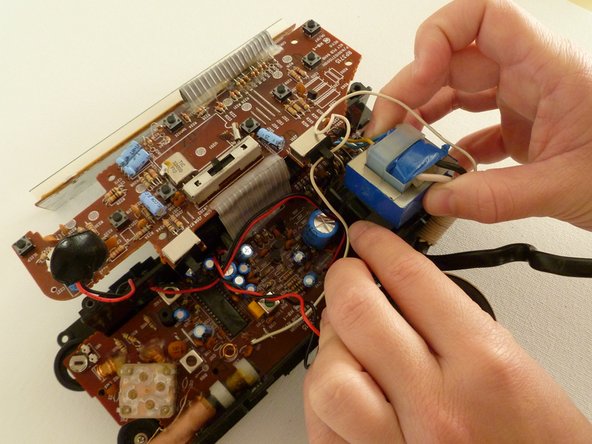
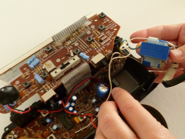

– Power Supply Liberation Time:
– Pop open the black tab sitting on the left side of the power supply.
– Carefully lift the power supply up and away from the black housing—no wrestling required.
– Let the power supply hang out just outside the clock casing (it’s still connected, so don’t go yanking it away).
Step 14
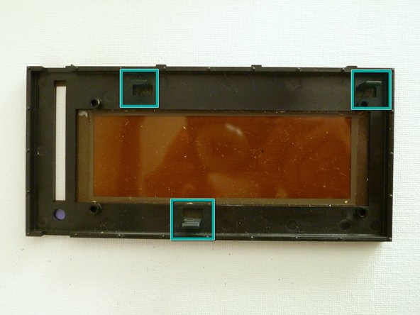
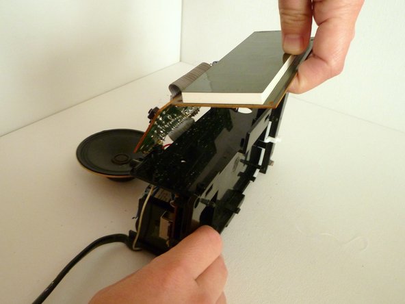
– Let’s get that Tinted Digital Display Window off! First up, you’ll notice it’s secured by some clever little tabs on the back. There are two up top and one on the bottom, just like in the picture.
– Gently release those two top tabs and smoothly pull the tinted display window away from the casing. You’ve got this!
Step 15

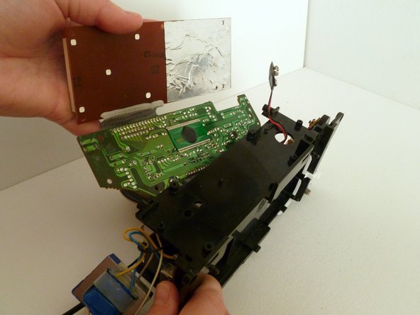
– Start by carefully removing the Digital Display and Top Logic Board from the Casing:
– Gently unlock the bottom tab on the digital display.
– Lift the display off the four corner pins like you’re setting it free.
– Peel off the digital display from the casing with a little finesse.
– Now, keep peeling back the top logic board off the casing, nice and easy.
Step 16

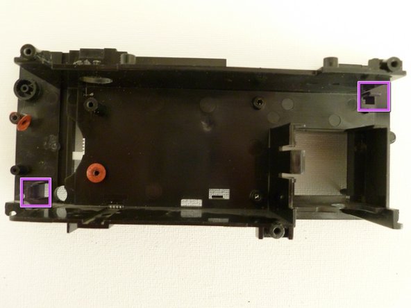
Heads up! The battery leads might catch on the casing as you work. Gently guide them through the circular hole on the casing to keep things smooth sailing. If you need a hand, you can always schedule a repair.
– Get ready to split up the digital display and logic boards from the casing.
– With the digital display and top logic board loosened up, flip the casing so the main logic board is on top and staring back at you.
– Look for the two little tabs locking the main logic board to the back casing—one’s at the upper right, the other at the lower left.
– Carefully lift out the main logic board from the casing. Steady hands win the day!
Step 17

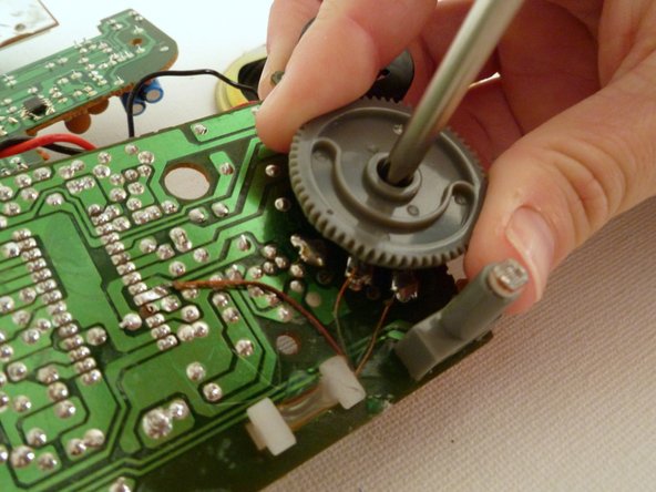
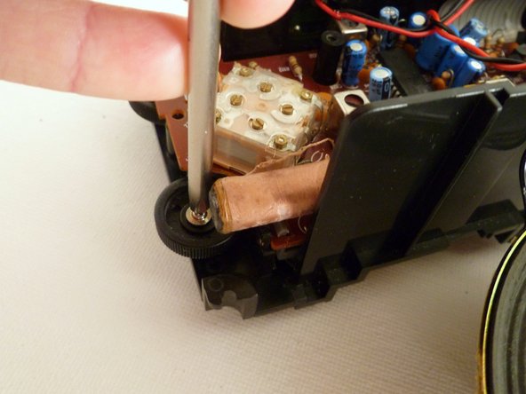
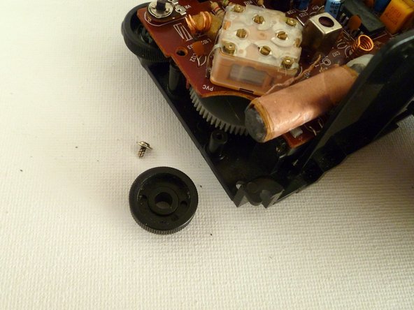
– Remove the Tuner Wheel:
– Time to get your hands dirty! Unscrew that grey tuner wheel from the back of the main logic board and lift it off. You’re making great progress!
Step 18

– The Clock Disassembled
– This is the point where the clock can’t be taken apart any further without cutting wires or requiring some soldering magic to put it back together.
– Here’s your clock fully deconstructed, ready for the next step in its repair journey!
Step 19
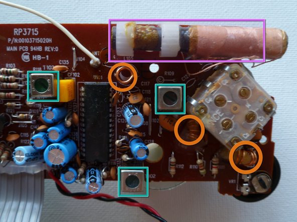

– Let’s take a quick look at the main logic board—it’s where all the radio components of the clock hang out. We’ll start by exploring the internal antenna, then move on to the tuning screws that help fine-tune the signals. Next up are the inductor coils, which are crucial for the radio’s performance. Finally, we’ll check out the power supply and transformer to keep everything powered up and running smoothly. If you run into any snags along the way, remember you can always schedule a repair with Salvation Repair to get professional help.
Step 20
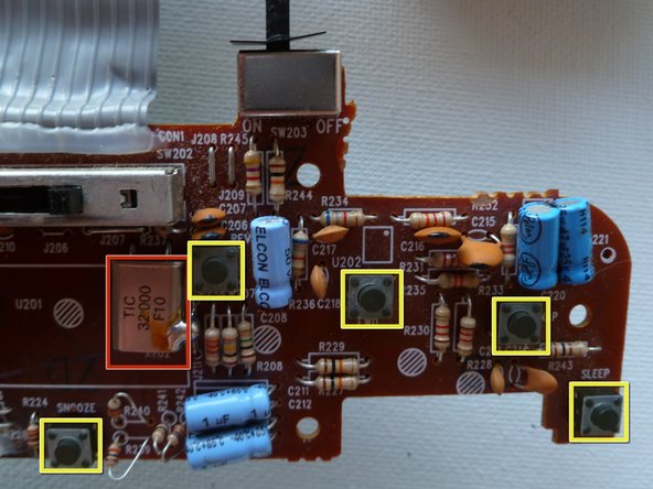

– Quick Look at the Top Logic Board
– Up here, you’ll find the clock and all the main controls chillin’ together.
– Clock Crystal
– Control Buttons
Success!