RCA RC2012 Alarm Clock Radio Teardown
Duration: 45 minutes
Steps: 13 Steps
The RCA RC2012 is your trusty alarm clock radio that’s ready for a little DIY action! Grab your screwdriver and some standard prying tools, and let’s get this tear down party started!
Step 1


– Your RC2012 alarm clock radio is all set and ready to rock!
Step 2


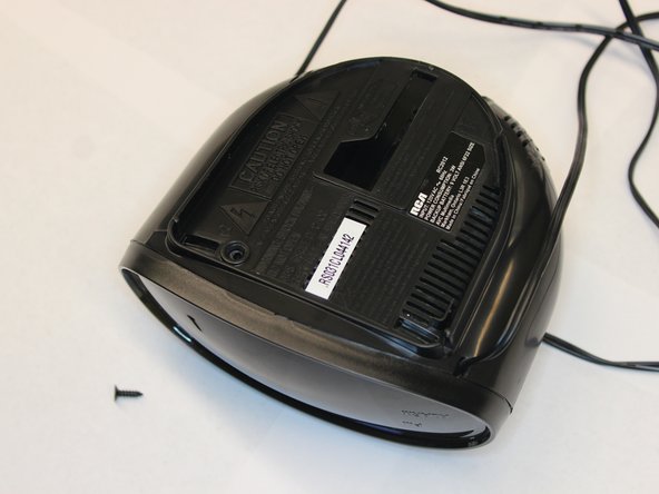
– Grab your trusty Phillips head screwdriver and remove that single screw from the bottom of your alarm clock radio. Easy peasy!
Step 3

– Gently prise open the alarm clock’s front panel by applying a bit of downward and forward pressure on the two tabs at the edges. Be gentle—those tabs are delicate and don’t want to be forced too hard. If you need extra hands, you can always schedule a repair.
Step 4

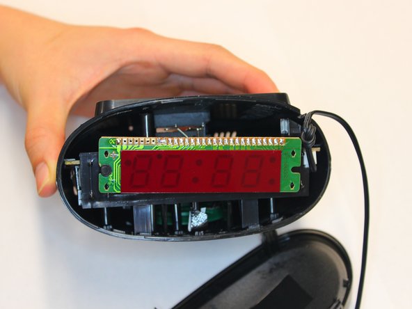
– As you pry up the front panel, keep an eye out for the gray shielded LCD connectors—don’t poke or damage them while you work!
Step 5

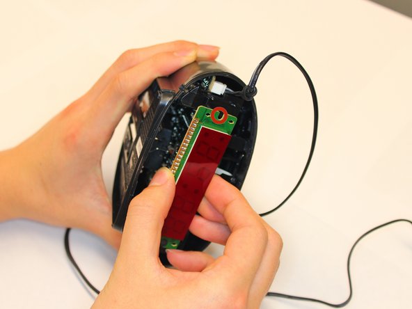
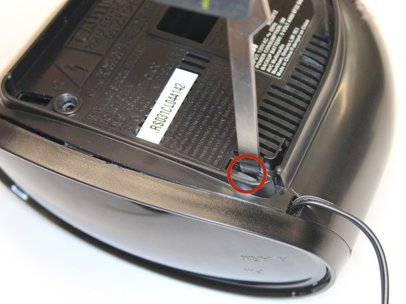
– Carefully work the LCD module loose from the alarm clock. You’ll notice two tabs (marked in red) holding it in place along the edge.
– Gently wiggle the module back and forth with your fingers until it pops free from those pesky plastic tabs. Just be mindful not to break them—if they snap off, your LCD won’t sit back in its spot properly.
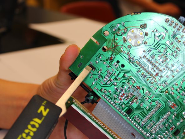
Step 6

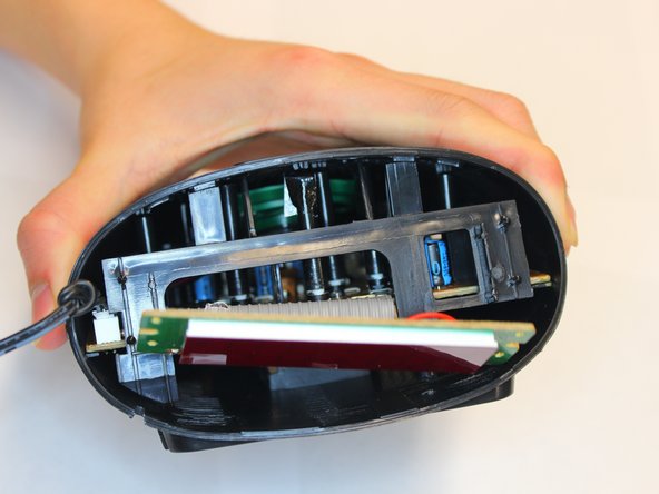
– Time to release that circuit board from its plastic home! Apply some firm pressure to both sides of the housing to get it loose.
– The PCB is snug in a plastic frame. Grab the frame with one hand and gently squeeze both sides of the alarm clock housing with the other hand to loosen it up.
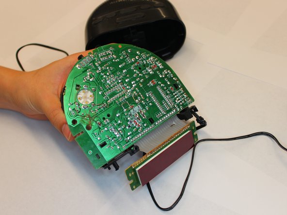
– Now, carefully pull the PCB out from the housing. It should slide out without too much trouble.
Step 7

– On the bottom side of the PCB, you’ll find three plastic tabs keeping the PCB and plastic chassis snug together.
– Take your prying tool and gently nudge each of the three tabs out of place. Don’t rush—just a little wiggle, and you’re good to go.
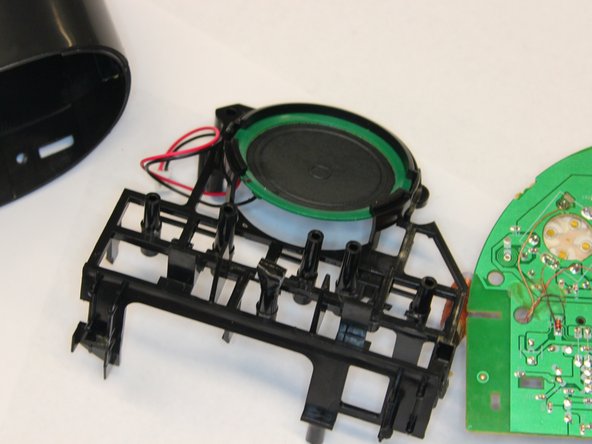
Step 8

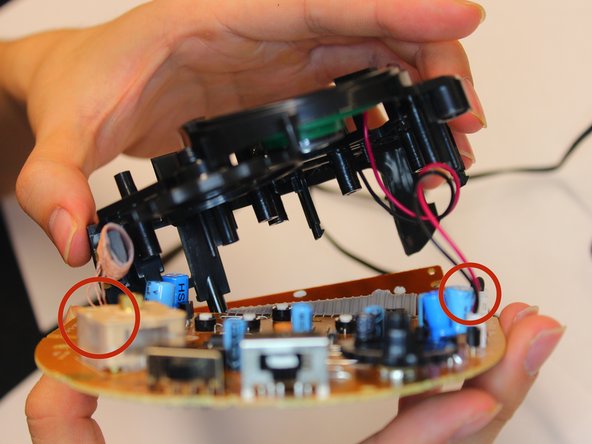
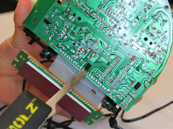
– Once you’ve taken out the plastic tabs from under the PCB, gently lift the plastic chassis up and away from the PCB.
– Go easy—don’t yank the chassis off. There are two pairs of pin connectors and a coiled antenna wire still linking the chassis and PCB.
Step 9
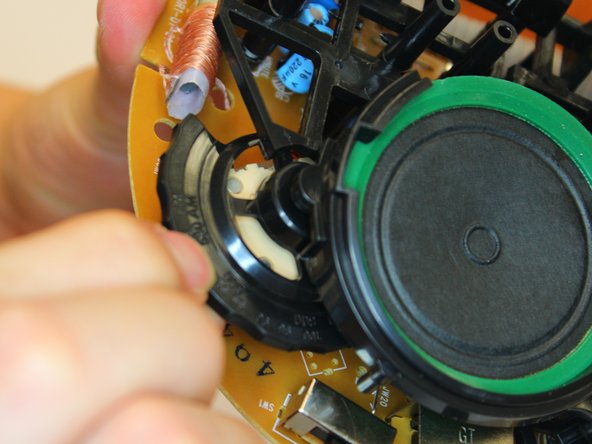
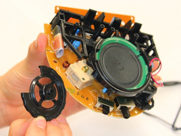

– You’ll find a nifty plastic dial nestled between the chassis and the PCB, and it’s the superstar that controls your radio’s frequency.
– To get that dial out of there, gently lift the chassis a bit and give it a little push upward. It should pop right out of its cozy fitting!
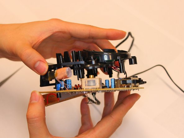
Step 10
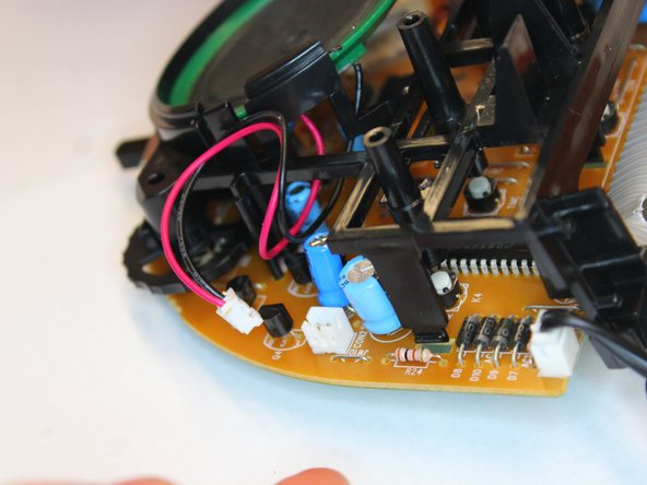

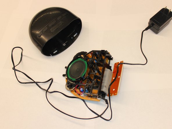
– Spot the two-pin connector linking the speakers on the chassis to the circuit board. That’s your target.
– Grab a small, pointy tool and press in the two little tabs on the connector that keep the wires locked in. While you’re pressing those tabs, gently wiggle and pull the connector wires until the male side pops free from the female side. Take your time—slow and steady wins the race!
Step 11

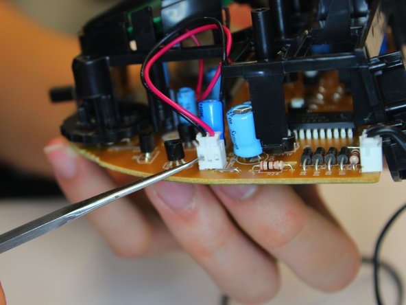
– You’ll spot a two-pin connector running from the chassis to the PCB—this is how the 120VAC adapter sends power to the board.
– Take a small, pointy tool and press down on the two tabs holding the wire crimps in the connector. While you’re keeping those tabs pressed, gently tug on the connector wires. The male and female connectors should come apart—like a polite handshake, but with less small talk.
Step 12

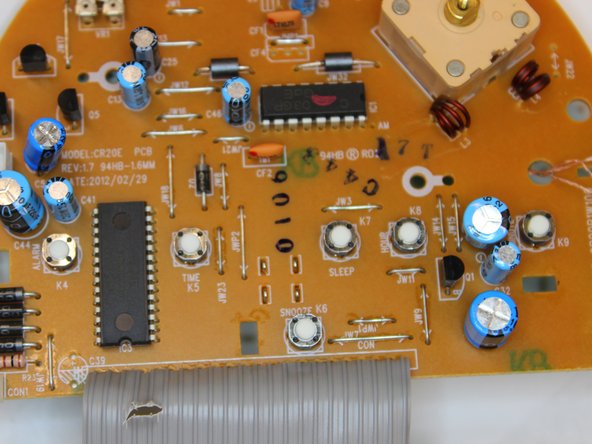
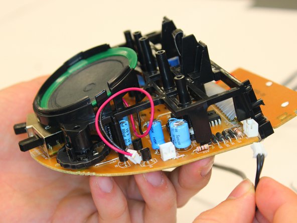
– Here’s a clear look at the top side of the PCB, all separated and ready for the next step—free from the plastic chassis. Let’s dive in!
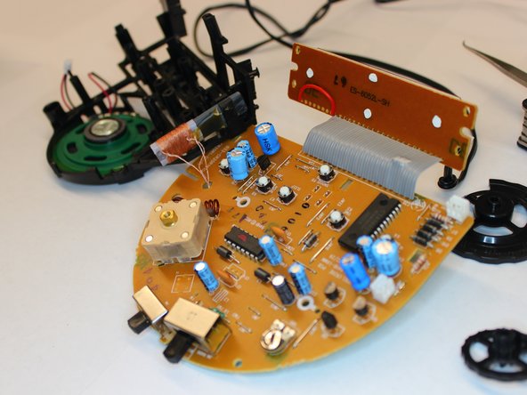
Step 13

– Take a good look at the underside of the PCB and the speaker that’s ready to roll.
Success!