RCA Studio II Teardown
Duration: 45 minutes
Steps: 11 Steps
The RCA Studio II is often remembered as one of the more ambitious (yet short-lived) video game systems of its time. In fact, PC World once labeled it ‘the worst video game system of all time.’ It didn’t really capture the hearts of gamers, mainly because RCA rushed it to market after missing out on the success of the Odyssey console. By the time it launched in 1977, the Studio II was already falling behind—no color display, no controllers, and by then, its competitors were offering both. RCA pulled the plug by 1979, and this console quickly became a rare collectible. We were lucky enough to get our hands on one of these rare beauties at Flash Summit 2010, just before it was set to head to the Computer History Museum. We managed to snap a few photos before it found its forever home. If you’re lucky enough to come across one of these vintage gems, take good care of it!
Step 1


– Back in 1977, RCA dropped its very first video game console, the Studio II, with a retail price of $149.95 (which would be about $525 today). It was actually priced about $20 less than most of its competition at the time.
– The Studio II came with five games already loaded up, but it also had a handy slot for external cartridges. Each cartridge cost you about $20 back in ’77, which would be around $70 in today’s money.
– One of the Studio II’s most charming features? Its box! Honestly, who wouldn’t want that red and blue striped polyester shirt in the photo?
Step 2


– The retro ’70s feel is alive and well along the sides of the box. One side proudly proclaims that it ‘works on any size Color or Black & White TV.’ Awesome! Just a heads-up: the Studio II only emits a Black & White signal. Inside, you’ll find five built-in games ready to play: Freeway, Bowling, Doodle, Addition (really?), and Patterns. If you need assistance, you can always schedule a repair.
Step 3


– This device keeps things simple with just five screws holding the two halves together—definitely less fuss than a PS3 Slim’s top cover, which needs about ten screws. Once those screws are out, lifting off the bottom cover is a breeze, revealing the inner components waiting to be serviced.
Step 4

Looking to lower the volume? Sorry, there’s no way to adjust it on this device.
– Get ready to explore a circuit board! It’s the backbone of your device, packed with tiny components waiting to be examined.
– The built-in mono speaker is the only source of the Studio II’s sound effects—it’s the device’s solo performer for audio output.
– Notice the large traces and widespread solder coverage? That’s classic 1970s electronics right there—big chips needed those hefty connections, and the generous use of lead was common before environmental rules kept things in check.
Step 5


The Studio II rocks a single, 18-foot-long I/O cable that’s soldered directly to the board. Yep, no connectors in sight—just pure commitment.
– Ooo, a sleek metal cover—what’s hiding underneath? Well, probably not much exciting. This shield is here to keep radio signals on point and stop any interference from messing with your device. No need to worry—just carefully remove it if you need to access what’s underneath. If you need help, you can always schedule a repair.
Step 6


The Studio II skips the classic power button and does something a little different. To turn it on, flip your RF switch to ‘Console Cord’—that powers up the Studio II and sends its signal to your TV. Want to turn it off? Just switch to ‘Antenna’ and your TV goes back to regular programming, while the Studio II takes a nap.
– Let’s talk about the I/O cable for a second. Here’s the Studio II’s RF switch.
– Now, inside that RF switch? You’ll find some capacitors and inductors—definitely hand-assembled with care!
Step 7

When’s the last time you spotted those classic white chip packages in the wild?
– Once you pop off the bottom cover, gently rotate the board out of the top case to unveil the hidden ICs on its top side. It’s like revealing a secret stash of goodies!
– Here are some of the key components attached to the board you’ll want to pay attention to:
– Controller inputs – your device’s way of talking to you
– Reset switch – because sometimes, everything just needs a fresh start
– Status LED – your device’s way of letting you know it’s thinking
– Channel select and sound I/O switches – for all your audio and channel-flipping needs
– Game cartridge socket – because who doesn’t love a good game?
Step 8

– The Studio II is powered by an RCA CDP1802 microprocessor clocking in at a blazing 1.78 MHz. With just 2K ROM, 512 bytes of RAM, and a 64 x 32 pixel monochrome graphics chip, let’s just say it wasn’t exactly wowing anyone—even in 1977. For comparison, a TI-83 calculator from 1996 hums along at 6 MHz and rocks 32 KB of RAM.
– The RCA CDP1802 was quite the quirky chip for its time. Some versions were built by layering a thin film of silicon onto a sapphire wafer. The sapphire’s super-low conductivity keeps any stray current (from cosmic radiation or whatever else the universe throws at it) from zapping nearby transistors.
– Thanks to this natural resistance to radiation, six RCA 1802 processors got to ride along on the Galileo spacecraft, handling operations for 14 years as it cruised around Jupiter and its moons. When Galileo’s job was done, it wrapped up its mission with a fiery plunge into Jupiter’s atmosphere in 2003.
Step 9

– These four ROM chips contain the original games that came preloaded in the Studio II, which are apparently copyrighted. In addition to the five built-in games, RCA released nine more cartridges, bringing the total to an impressive 14 titles. To put that in perspective, compare this to the over 900 games available for the Atari 2600 (along with its iconic joysticks), and you’ll see why the Studio II didn’t quite hit the mark. If you need help with this process, you can always schedule a repair.
Step 10

Check this out: every component on this circuit board uses through-hole technology. Even though surface-mount parts had been around since the ’60s, through-hole was still the budget-friendly, go-to choice back in the day.
– Here’s a close-up shot of the Studio II’s RF modulator, showing how the power supply connects through this cable, which is separated for clarity. Also, take a look at the trace patterns across the board—they’re definitely hand-drawn, a common sight before computer-aided design took over. Most of those wide solder areas are actually the ground plane. If you need help with any step, you can always schedule a repair.
Step 11

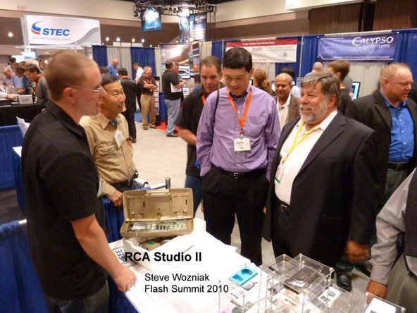
– For a console that’s pushing 30 years old, the RCA Studio II really hung in there. But, in the end, it couldn’t avoid its inevitable fate as the ‘worst video game system of all time.’
– We recently gave Woz a look at the console. He had a blast with it since it was developed around the same time as the Apple II. Unlike the Apple II, though, the Studio II didn’t come with circuit schematics.
– Be sure to check our teardown page or blog for an in-depth dive into another retro game console tomorrow!
Success!