
Repair iPhone X Battery that Drains Fast
Duration: 45 minutes
Steps: 16 Steps
Step 1


- So, the iPhone X battery is draining faster than usual and overheating? Not cool, right?
- This speedy battery drain usually happens because of a tired old battery or current leakage from the motherboard.
- Replaced the battery, but the drain still won't stop? Looks like the culprit could be that pesky motherboard current leakage. Time to dig a little deeper!
Step 2

- Next up, let’s get our motherboard powered with a DC Power Supply to check the current. It looks like we have a little current leakage going on at 186 mA. Let’s keep our spirits high and tackle this together!
Step 3


- If your motherboard is leaking current after being powered up, let's get our detective hats on! We can measure the power supply circuits to track down the culprit causing the trouble.
Step 4


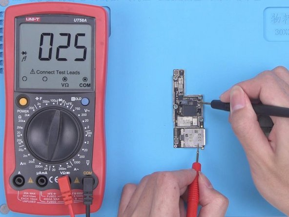
- First up, let’s check out PP_BATT_VCC. Resistance looks totally normal—so far, so good.
- Next, let’s take a peek at PP_VDD_Main. The resistance clocks in at 29, which is on the lower side. This hints that there’s a suspect component hanging out on PP_VDD_Main. Since the current is pretty low, rosin won’t help us spot the culprit. Time to break out the thermal imager and hunt down the troublemaker!
Step 5

- Start by powering up the PP_VDD_Main on the motherboard. You might not see an immediate temperature change, but that's okay. It just means the issue isn't with the surface layer of the motherboard.
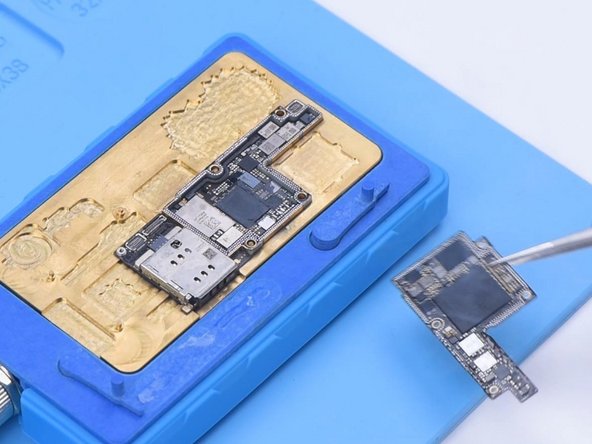
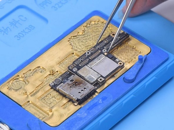
- Next, carefully detach the motherboard for more in-depth testing. Place it on the Heating Platform and let it heat up. Once it hits 165 °C, it's time to separate the logic board from the signal board.
Step 6

- Once the motherboard's had a chance to chill out, let’s check out the PP_VDD_Main on the logic board. The resistance is right where it should be—nice!
- Now, let’s do the same on the signal board. Uh-oh, that resistance value is acting up. Looks like we’ve got our troublemaker: the signal board is the culprit.
Step 7

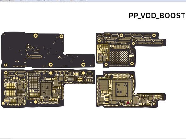
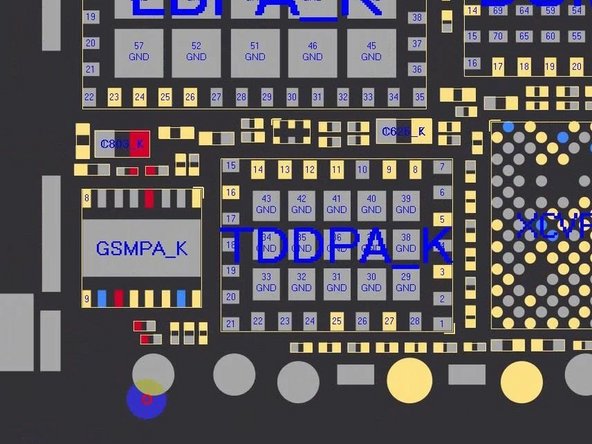
- Open the bitmap to spot where PP_VDD_Main is hanging out. Keep an eye on the signal board with your Thermal Imager—so far, the temperature’s playing it cool with no big changes. The bitmap reveals that PP_VDD_Main is also chilling under the card reader.
Step 8

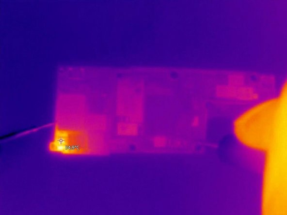
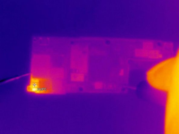
- Alright, it looks like the culprit is probably hiding under the card reader. Let's give the back of the signal board a check using the Thermal Imager. See that temperature spike at the top left of the card reader? That's your sign—looks like the issue is hanging out in that area.
- Next up, time to remove the card reader. Don’t forget to apply a little Paste Flux to the bonding pad. To keep the plastic part safe and sound, we’ll coat it with some low-temp Solder Paste to balance out that heat from the bonding pad. Nice and easy!
Step 9

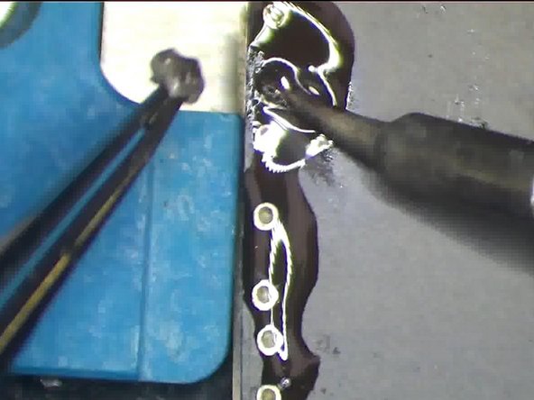
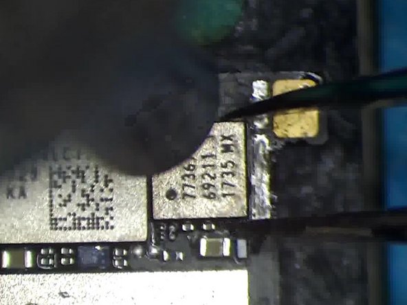
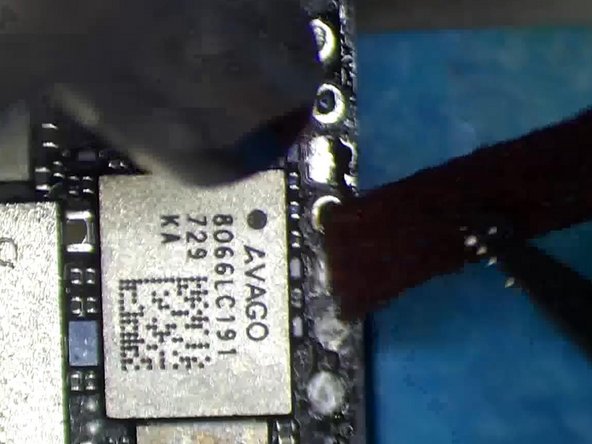
- Next up, grab your trusty Hot Air Gun and set it to 340°C. Gently heat the card reader while using your Pry Blade to carefully lift it. Once it starts to feel a bit loose, go ahead and remove it!
- Keep an eye on things with the Thermal Imager as you work. You'll notice the card reader area heating up. From the thermal map, the hot spot is likely the GSM. Looks like it’s time to swap out the GSM!
Step 10

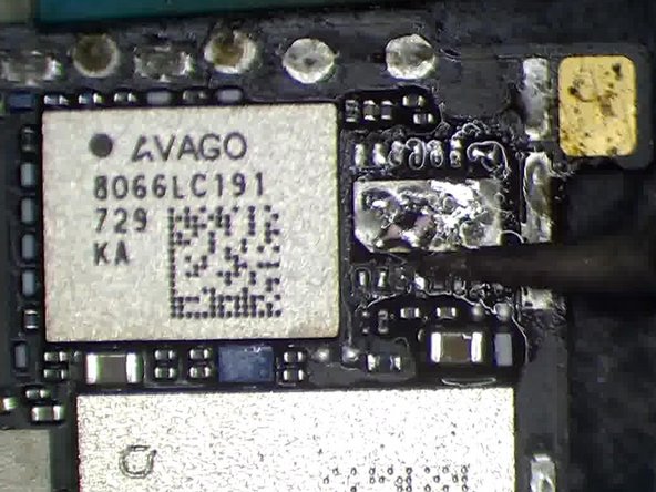
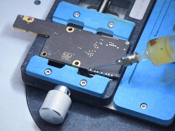
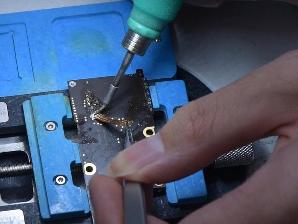
- Start by adding a little Paste Flux to get things rolling. Then, gently remove the GSM with a vertical wind Hot Air Gun set to 340°C. After that, throw some more Paste Flux on there, along with a bit of middle-temperature Solder Paste on the bonding pad. This helps to cool things down and keep the pad in check for the next steps.
Step 11


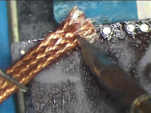
- Grab your Hot Air Gun and some Solder Wick to clean up that bonding pad. Once that's done, give it a quick clean with some PCB Cleaner. Now, it's time to check the resistance value of PP_VDD_Main.
- If everything looks good and the resistance value is back to normal, you're golden!
Step 12


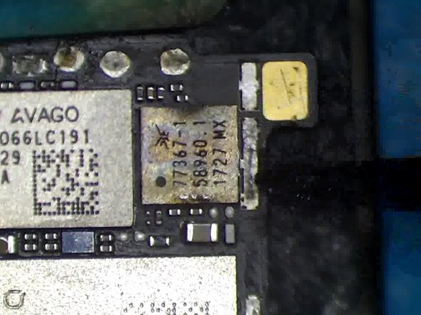
- Time to pop in a trusty GSM chip! Dab on some Paste Flux, set the GSM right where it belongs, then hit it with a vertical blast from your Hot Air Gun at 320 °C.
- Once everything’s soldered up, grab your multimeter and check resistance again. If the numbers look good, you nailed it!
Step 13

- Keep dabbing on that low-temperature Solder Paste to the bonding pad of your card reader like it's the secret sauce to a tasty dish!
- Give that bonding pad a good clean-up with a Hot Air Gun and Solder Wick. Then, switch it up and tidy the back bonding pad using a Soldering Iron and Solder Wick. It's like a spa day for your device!
Step 14

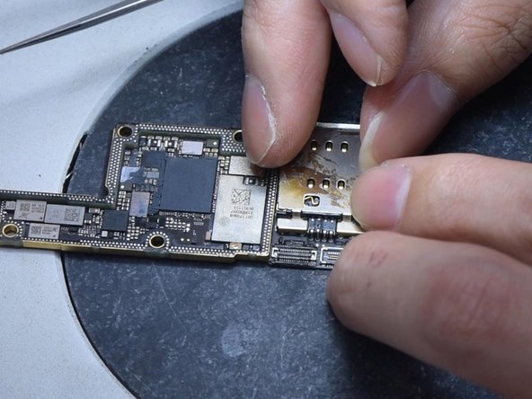
- Now, give those pins a good clean with PCB Cleaner — you'll see them sparkling in no time.
- Next up, let's get that card reader in place. Slide it right where it belongs.
- Time to secure the card reader! Solder the back bonding pad using your Soldering Iron. If you find any extra solder, gently flatten it with Solder Wick — just don’t drag the wick while removing solder. Finish by cleaning the bonding pad again with PCB Cleaner.
Step 15

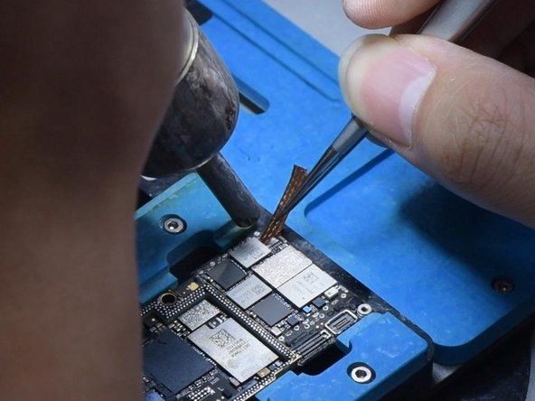
- Now, let's get the motherboard back together. Place the signal board on the 165°C Heating Platform to warm up. Dab a little Paste Flux on the bonding pad, then carefully line up the logic board with the signal board. Once it hits 165°C, you can safely remove the motherboard.
- To make sure everything’s snug, gently press both sides of the motherboard with tweezers. A little pressure goes a long way.
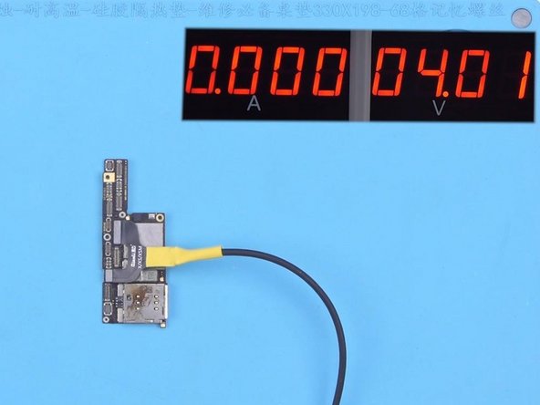
- Next, power up the motherboard for a quick test. Check that the current is normal, and you’re good to go!
Step 16

- Plug in the screen to give it a test run. Boot current looks good and steady. The sneaky current leak is gone—mission accomplished!


