Replace Google Pixel 2 XL USB Port Guide: Step-by-Step Tutorial
Duration: 45 min.
Steps: 19 Steps
In this super cool guide, we will guide you through the process of bringing your Google Pixel 2 XL’s USB connector back to life, no problem! You’ll want to give this repair a go if your computer doesn’t recognize your phone or you can’t charge it. Be aware that this might be a tricky repair. The screen is glued down, so we only recommend you try this one if you feel ready to take on removing the screen without cracking it. You’ll also need to get yourself an adhesive frame to seal the display back up after you’re done. Let’s get this show on the road!
Step 1
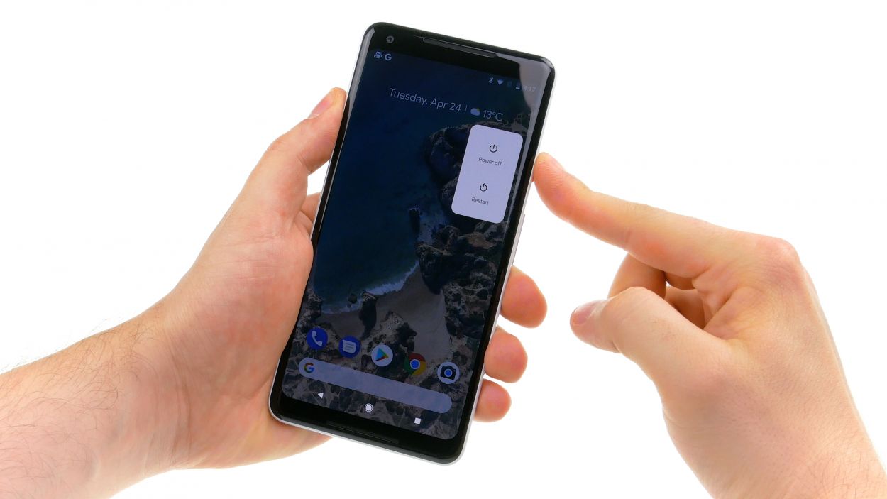
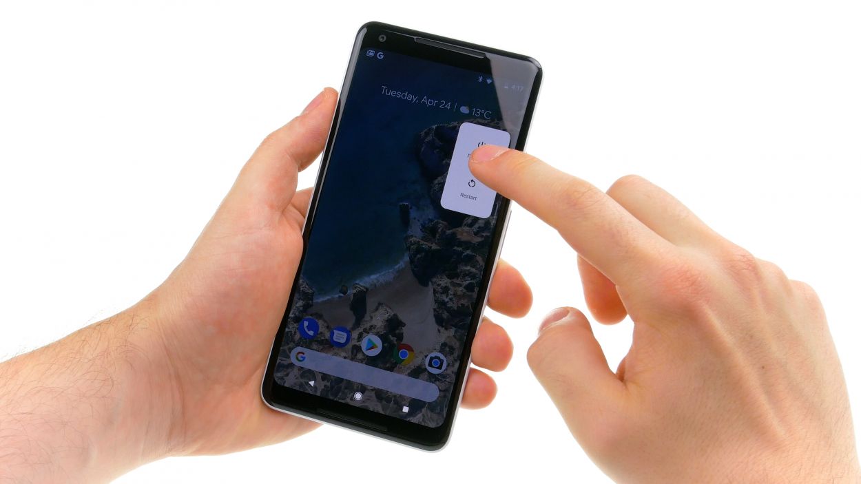
– Give that standby button a good press and hold until you see the magical words ‘Power off’ pop up on your screen.
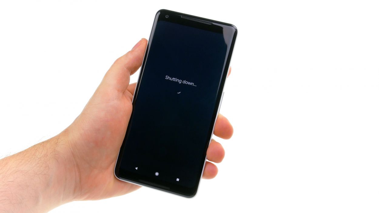
– Give it another tap to confirm and hang tight while your device takes a little nap.
Step 2
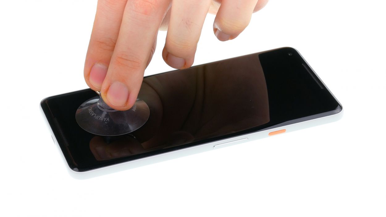
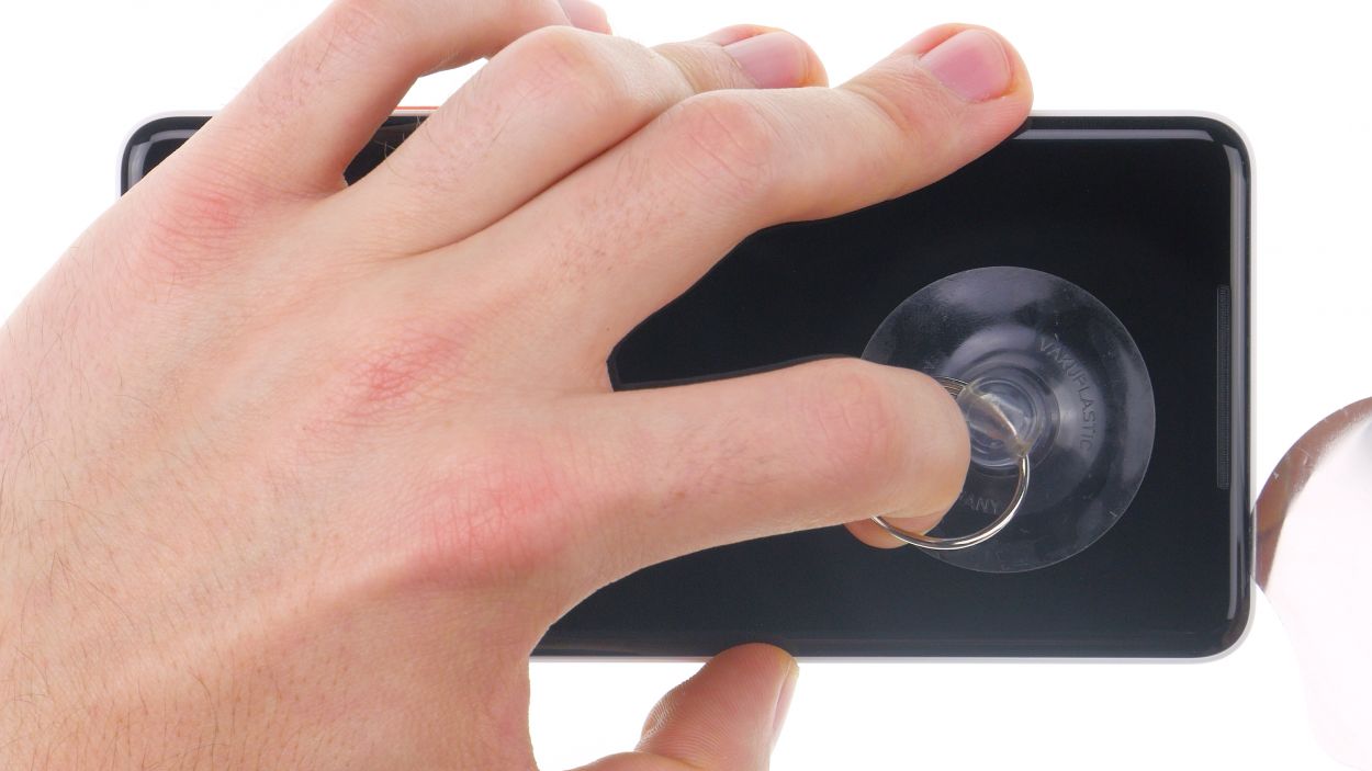

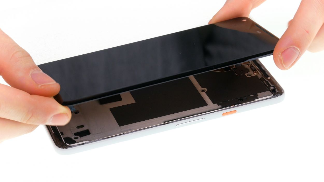
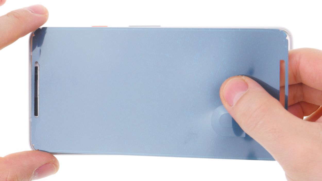
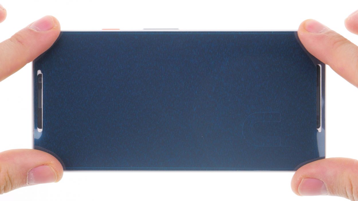
– Start by warming up the glue around the edges with a hot air tool until it reaches about 60°C. Give it another go and heat the display just enough so that it’s almost too hot to touch.
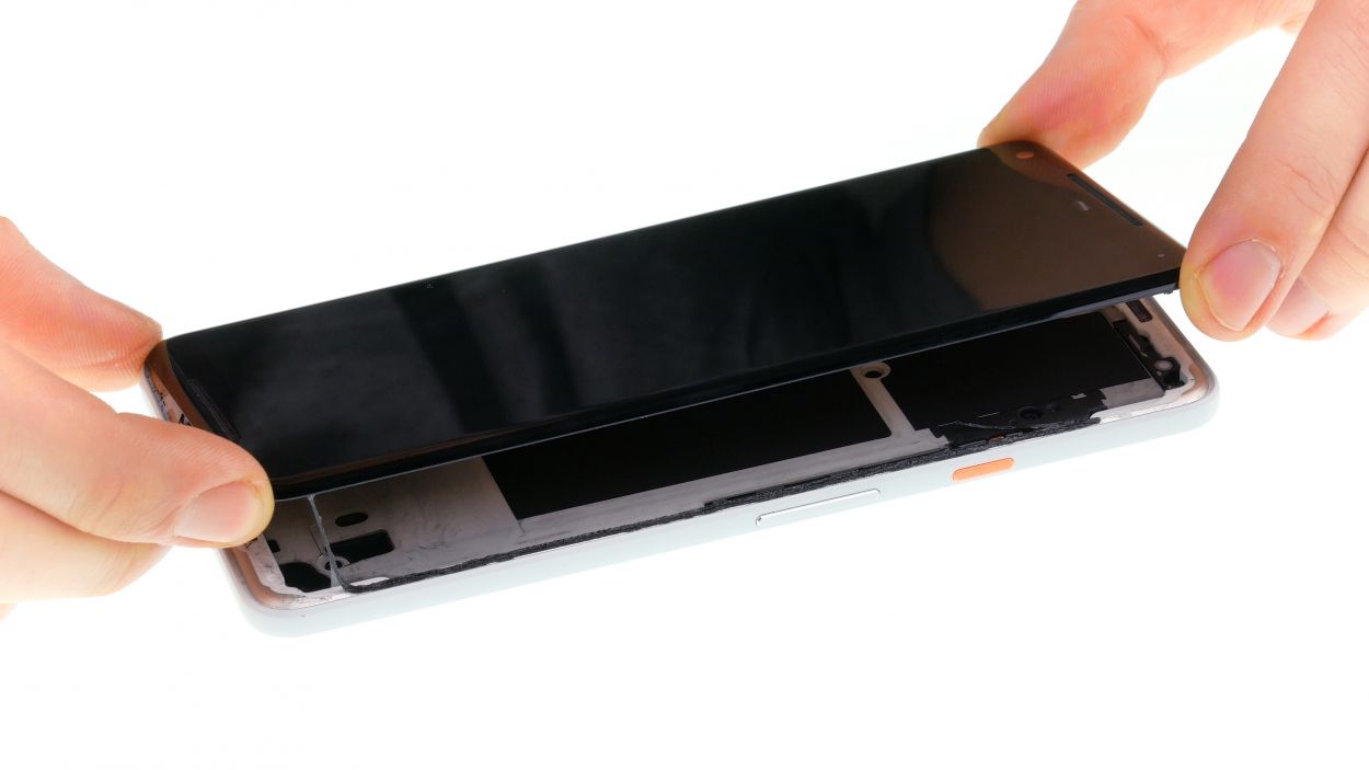
– Next, grab a suction cup and place it at the bottom of the display, right over the USB connector, then give it a gentle pull.
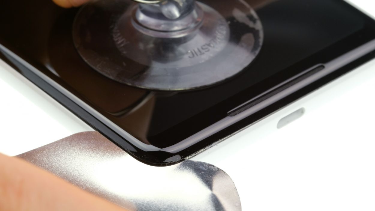
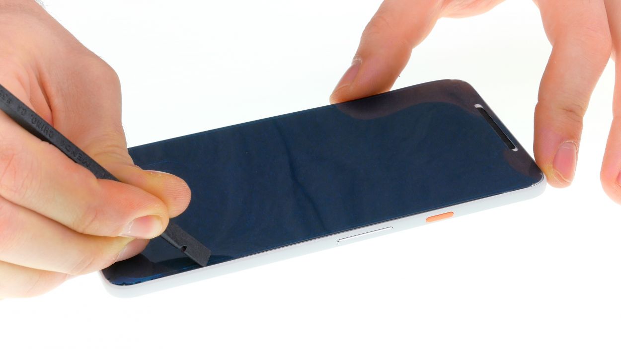
– Now, take a super thin, flat tool and carefully slide it between the display and the frame, moving it around the edge to pop one corner of the display loose.
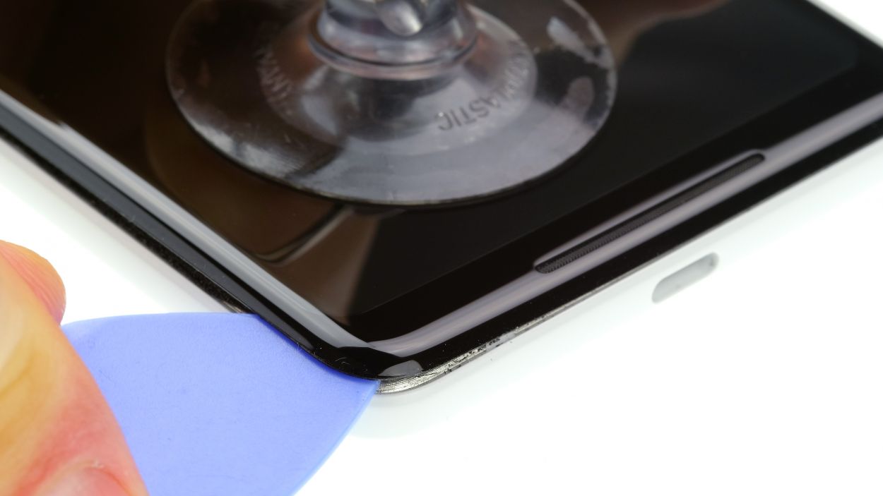
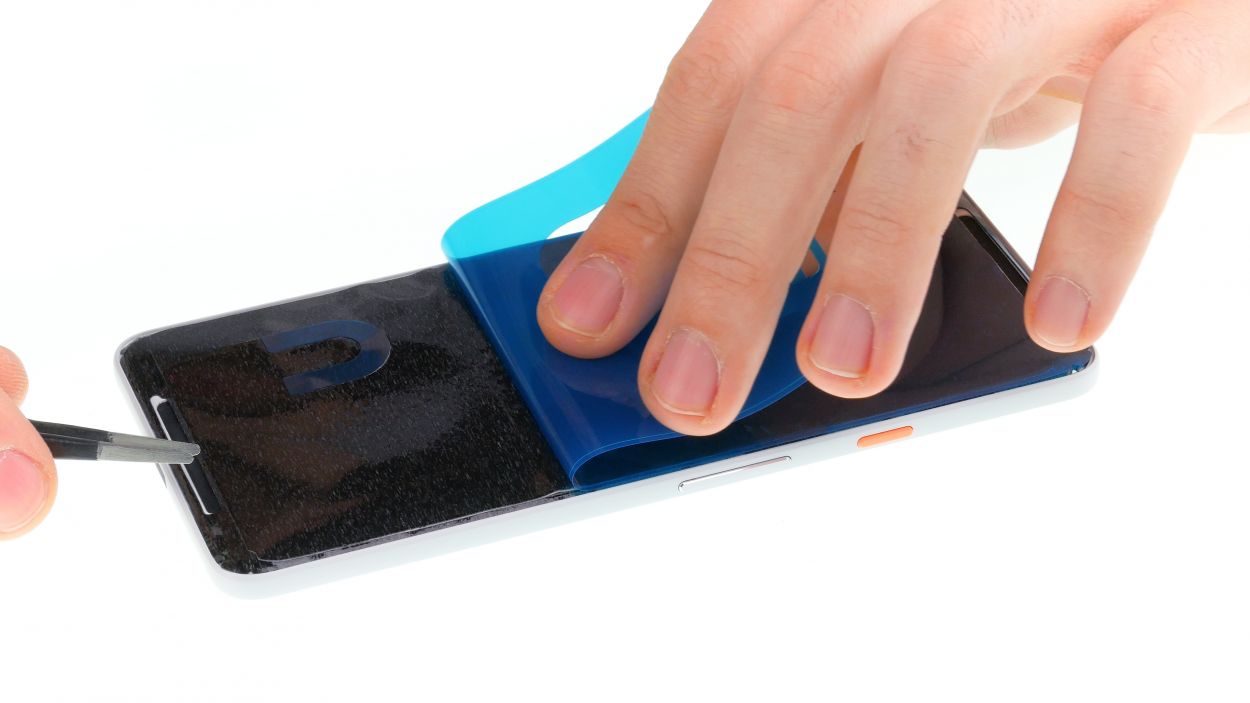
– Slide a pick in between the frame and the display. Feel free to use additional picks to help detach the display all the way around. Just remember, no tool should go deeper than 5 mm!
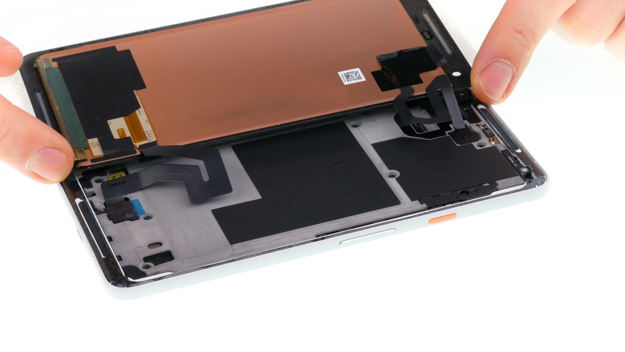
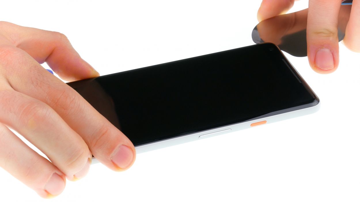
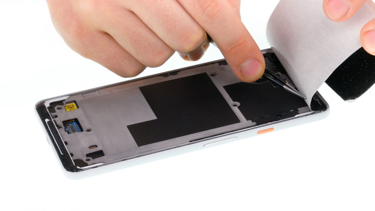
– Once the glue is all loosened up, you can lift the display off. Gently fold it back towards the top (just like in the picture), but be cautious as there are still two flex cables connected.
Step 3
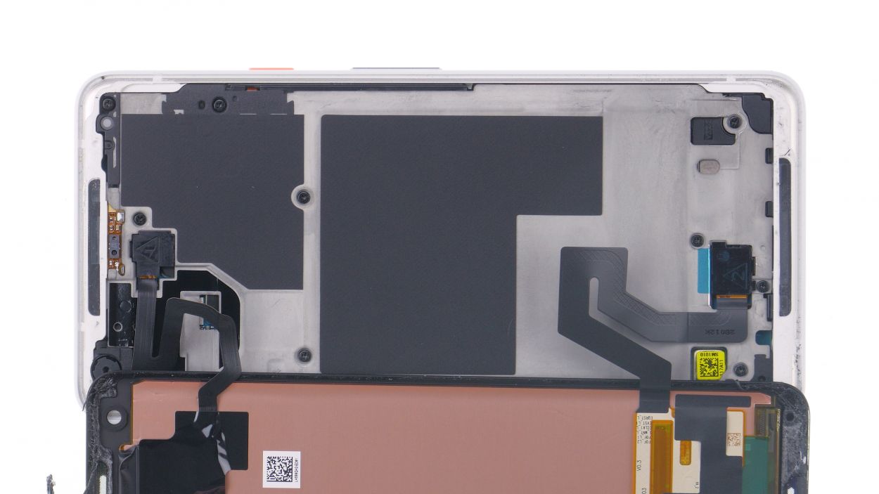
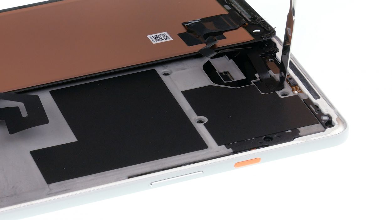
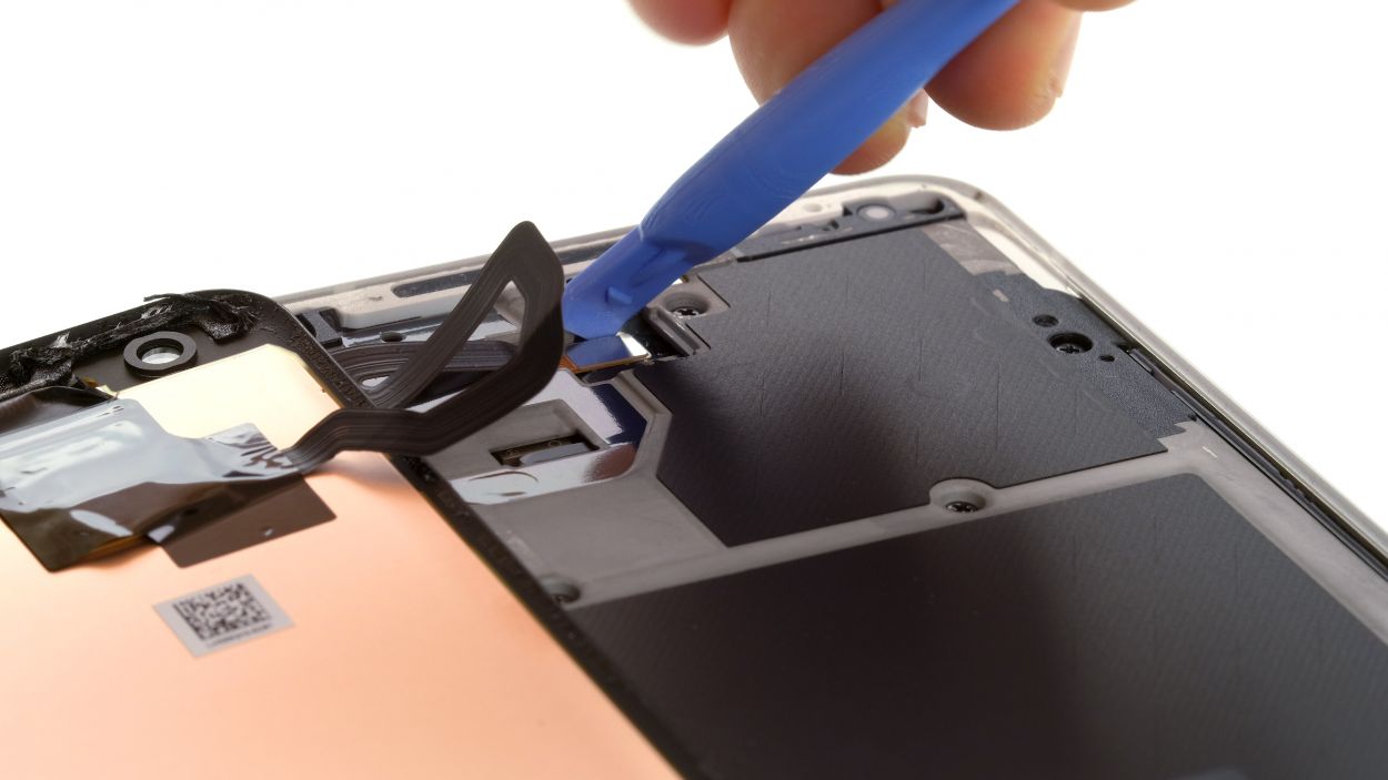
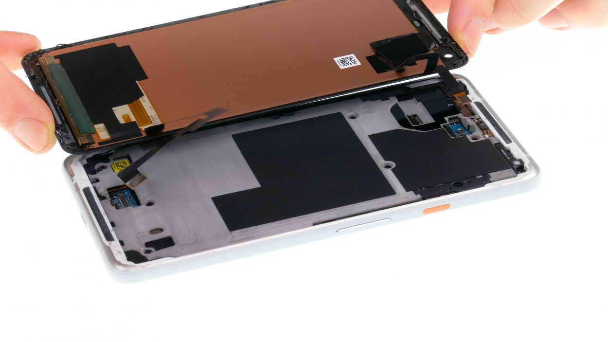
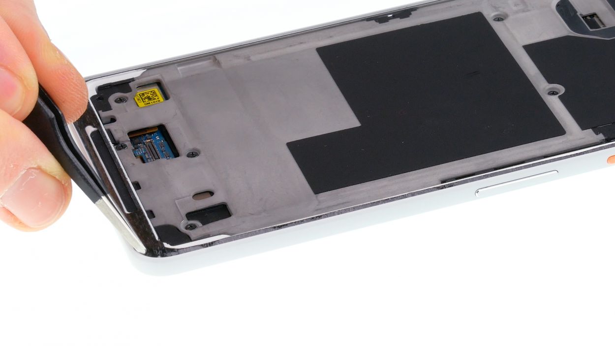
– Gently lift the display, making sure not to put too much pressure on those sensitive flex cables hiding beneath. They’re delicate little guys!
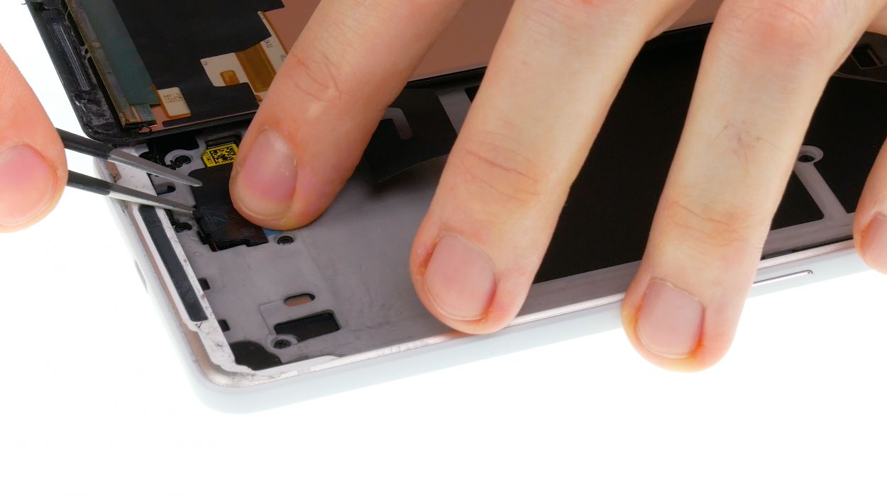
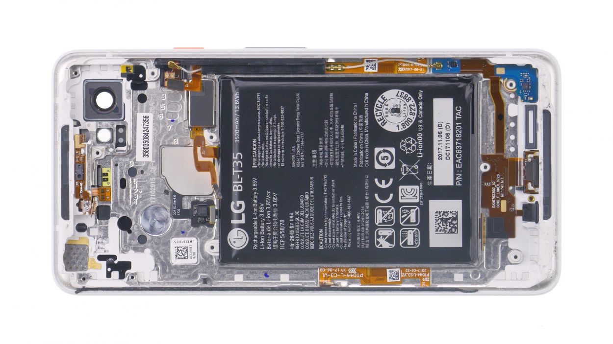
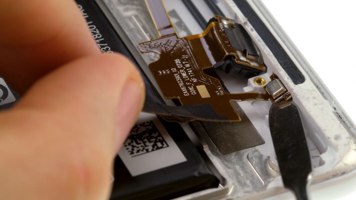
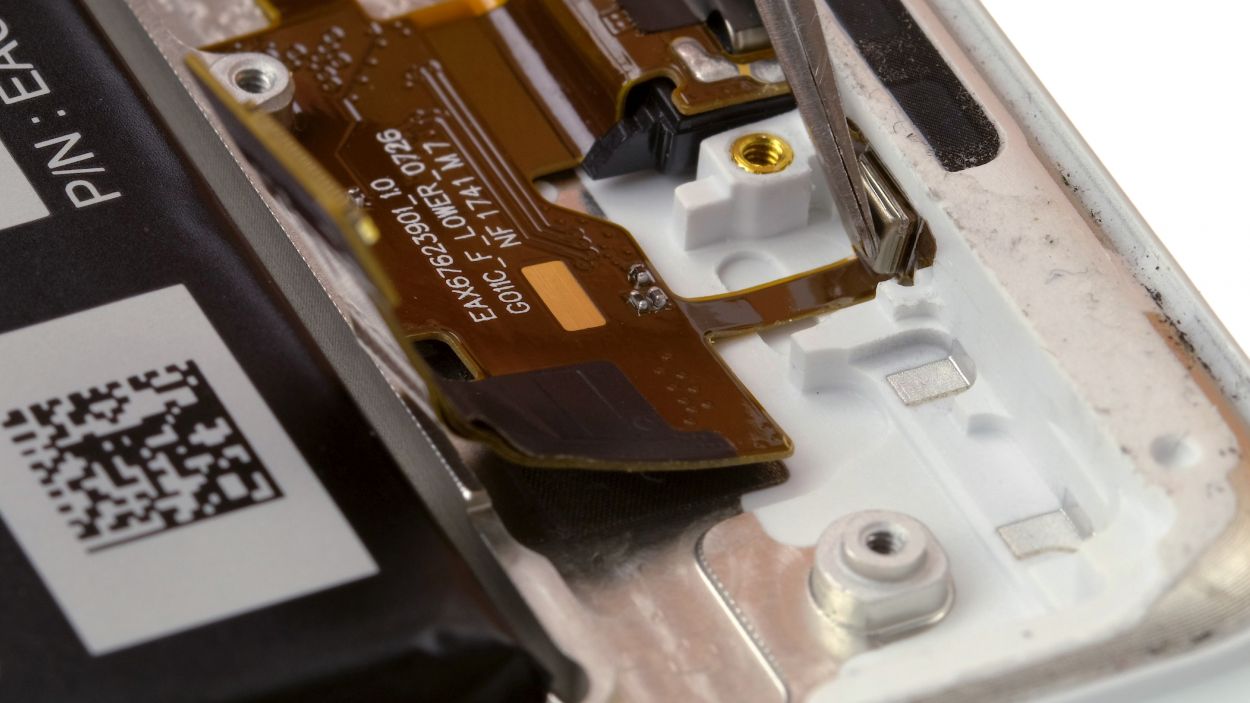
– Next up, it’s time to tackle the plastic cover labeled ‘1.’ Use a flat tool to slide into the gap and gently pry it free. Easy peasy!
– Now, let’s get cover number 2 out of the way. Don’t forget to detach that tiny tape strip—it’s a sneaky one!
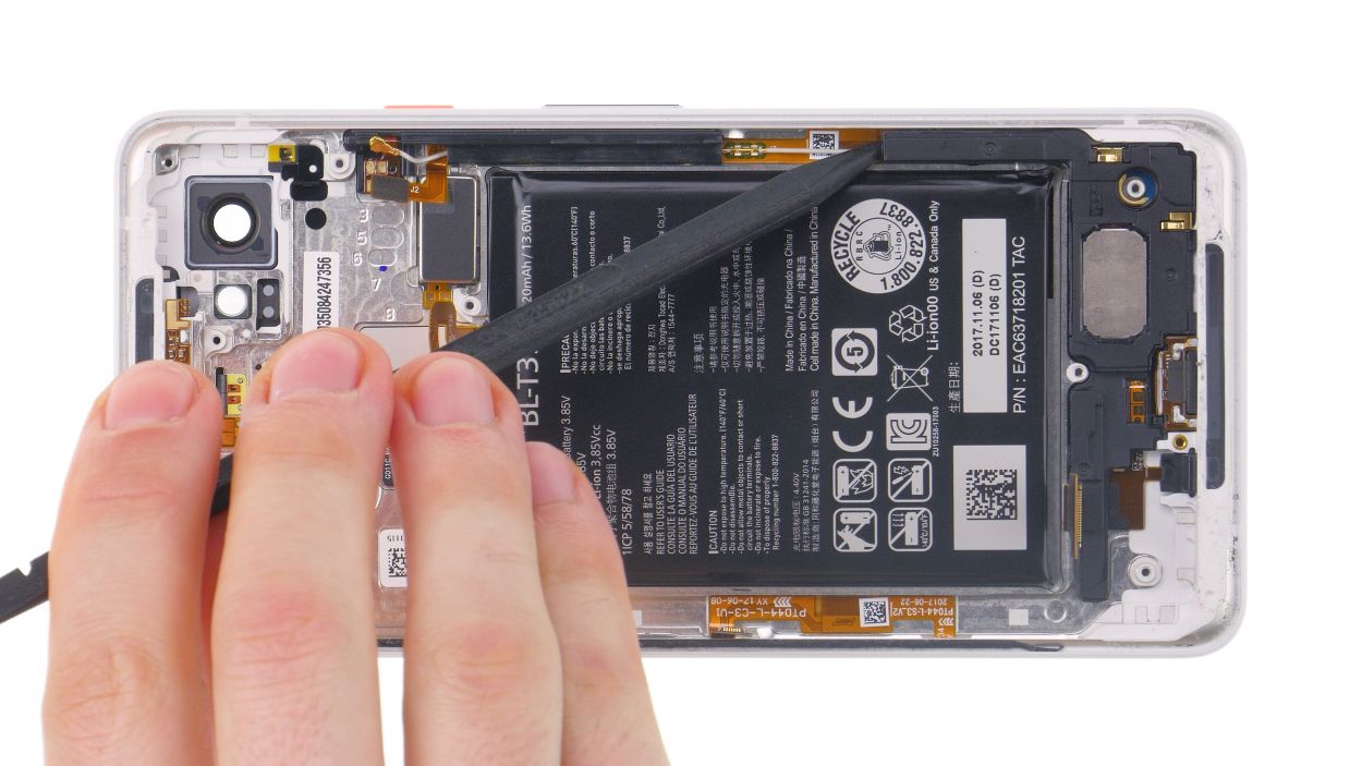
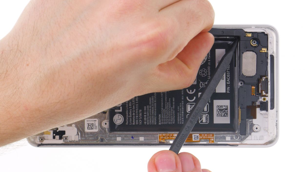
– Finally, grab your trusty spudger and unplug both connectors with care. You’ve got this!
Watch out for that lower contact! Right next to the connector, there are some sensitive components on the circuit board just waiting to be bumped. Handle with care!
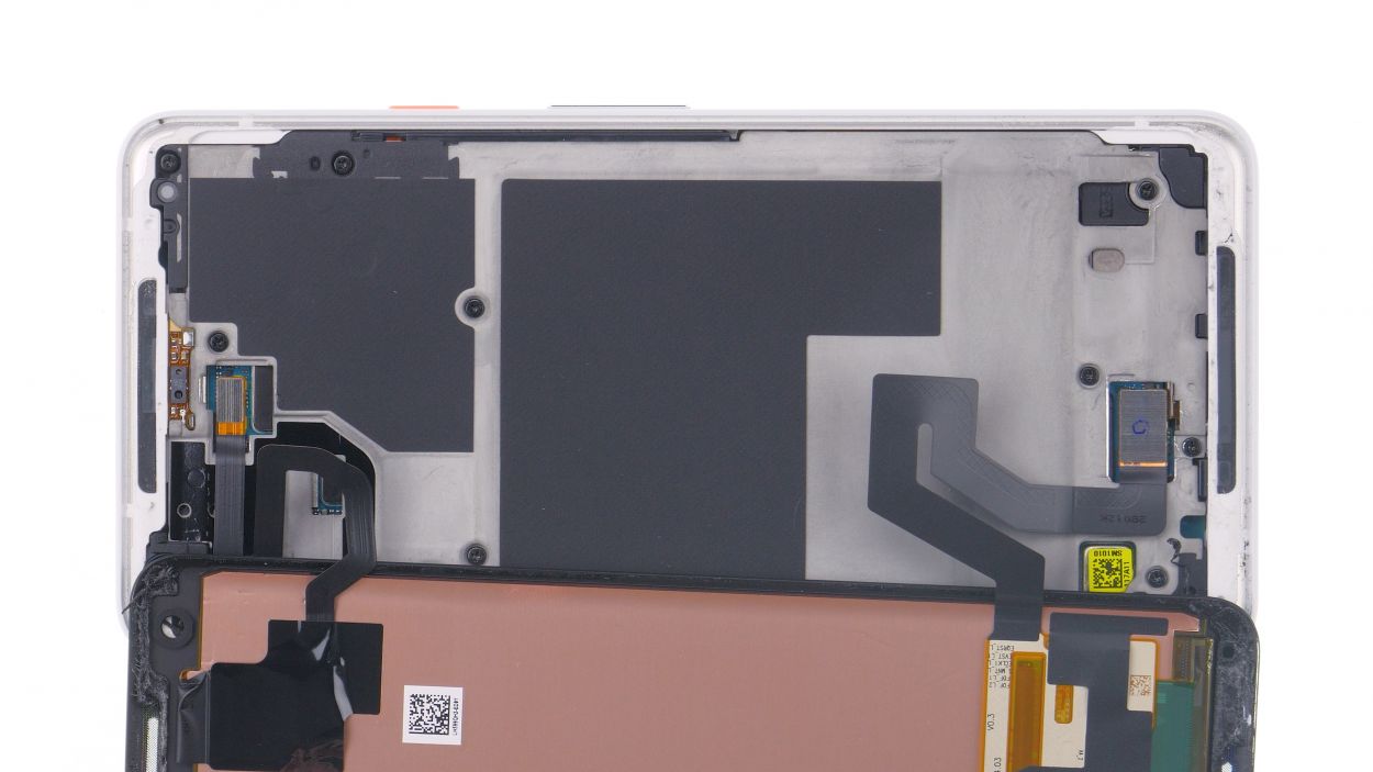
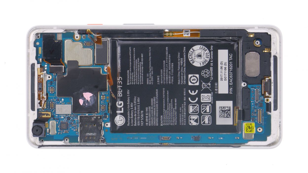
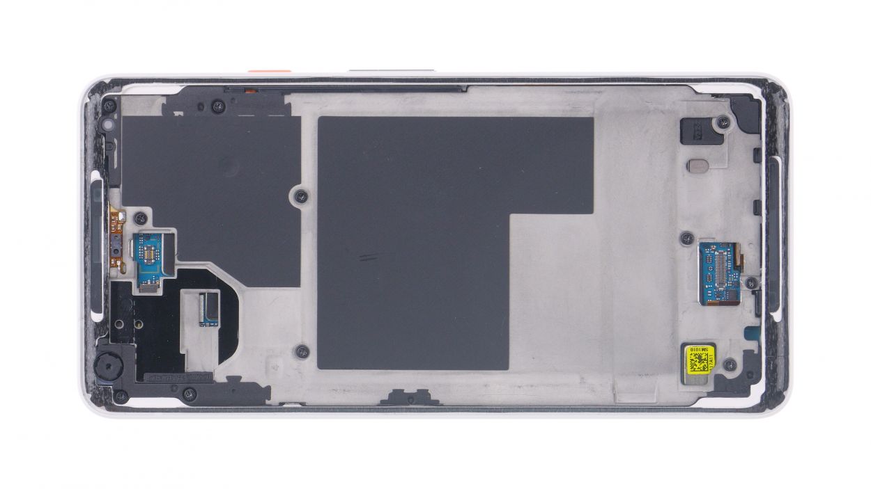
Step 4
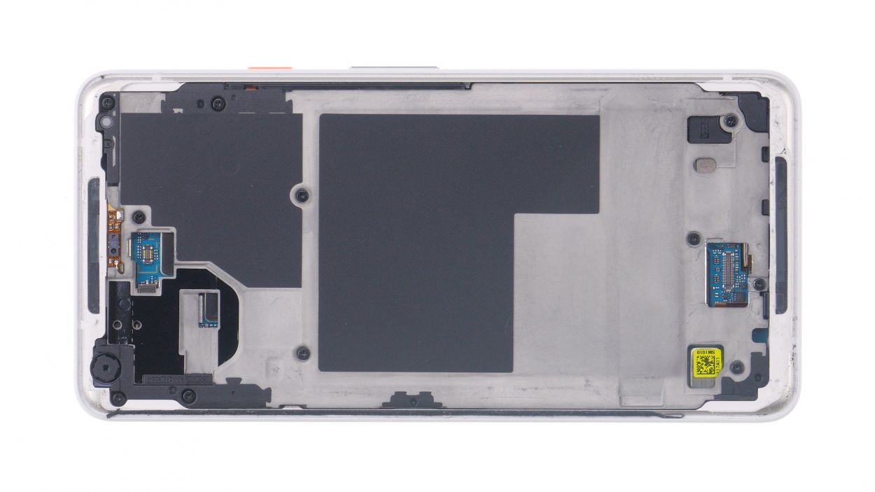
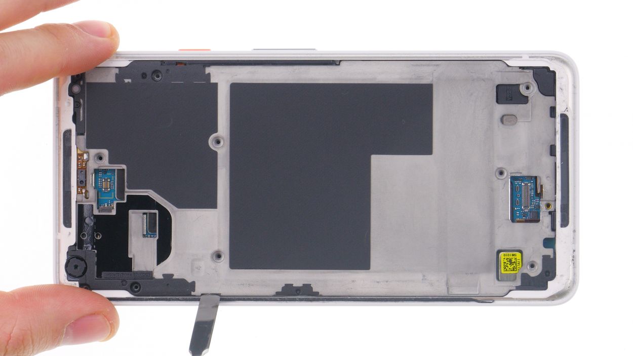
11 × 2.7 mm Phillips
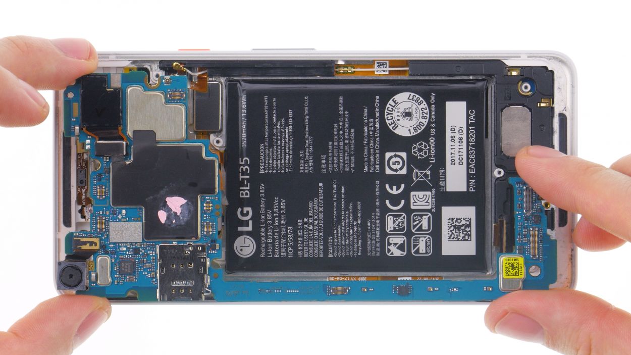
– First things first, unscrew all those little screws and keep them in one spot—trust me, they’ll appreciate not getting lost! They’re all the same length, so mixing them up won’t be an issue.
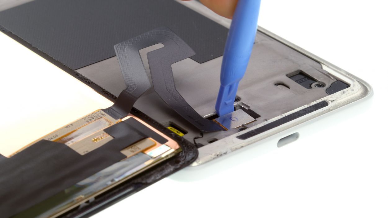
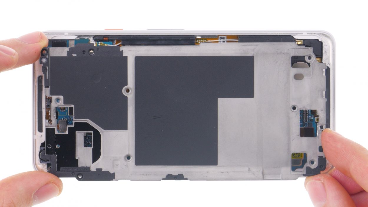
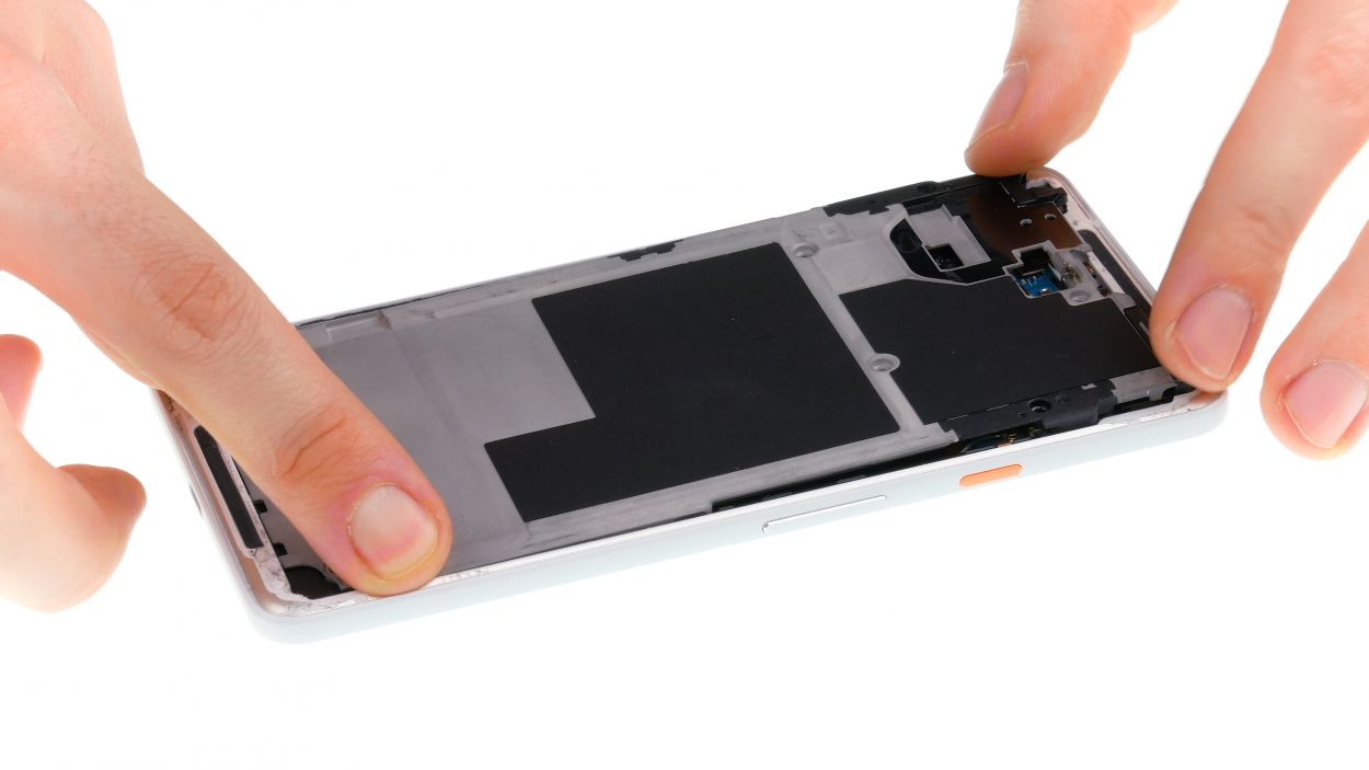
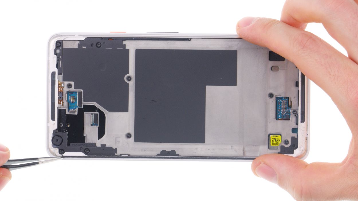
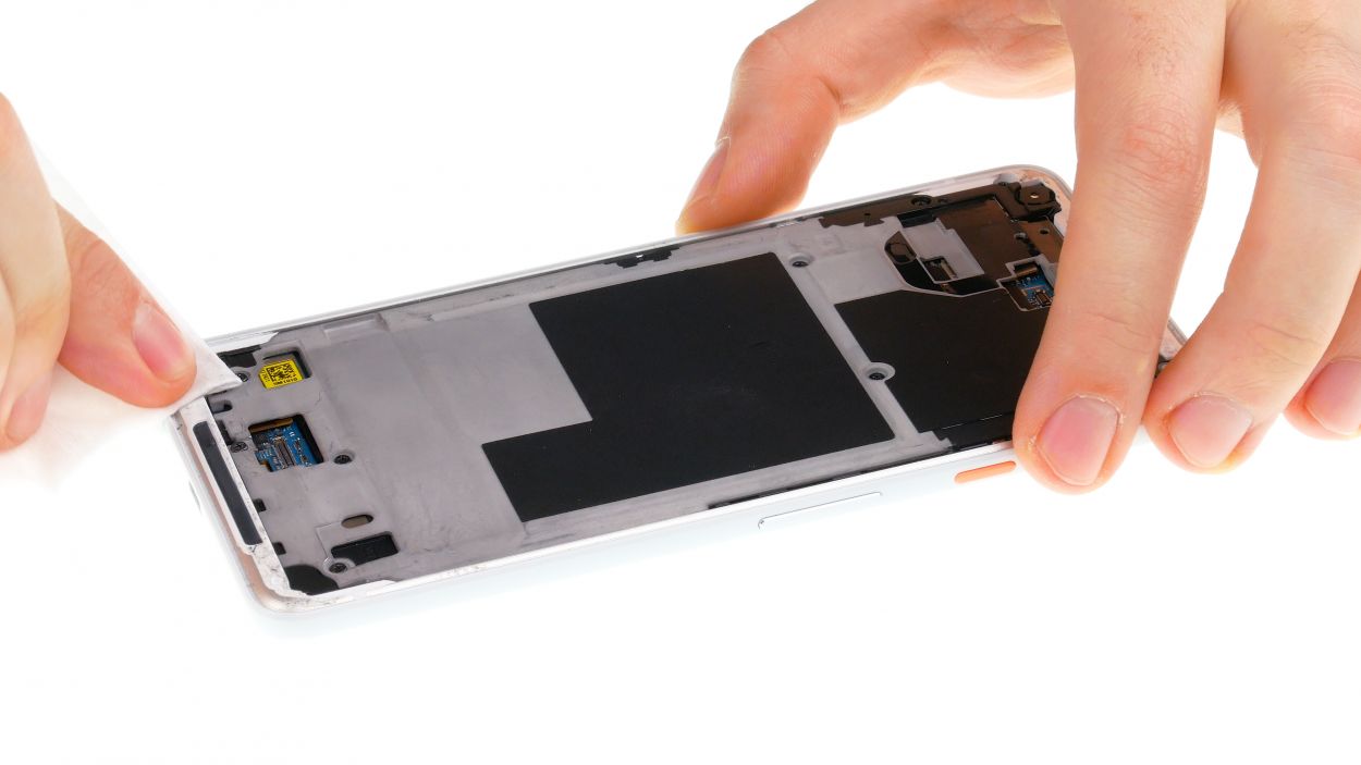
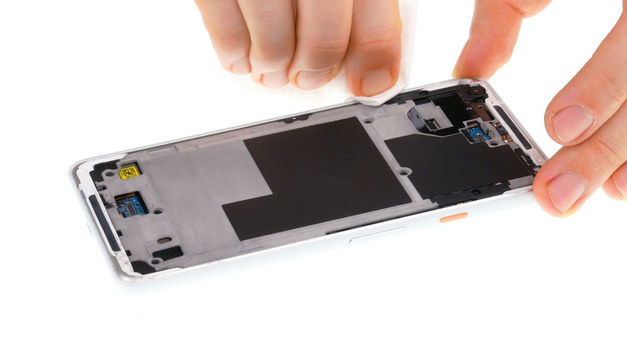
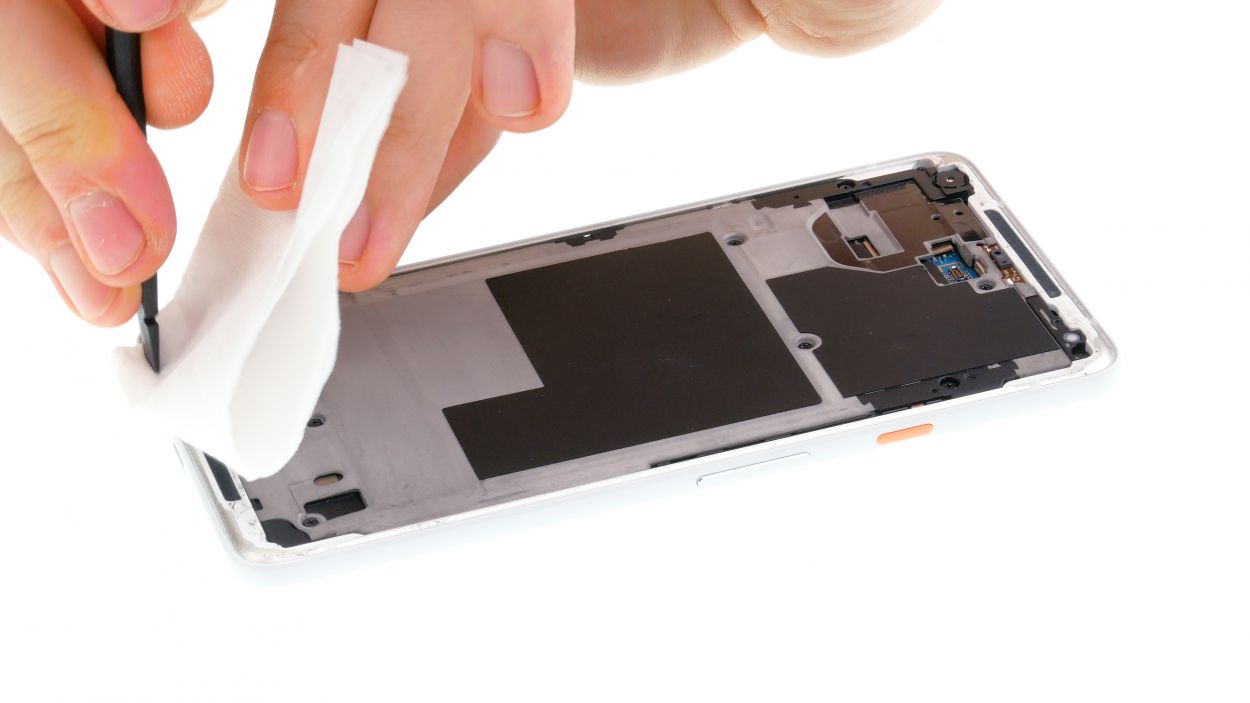
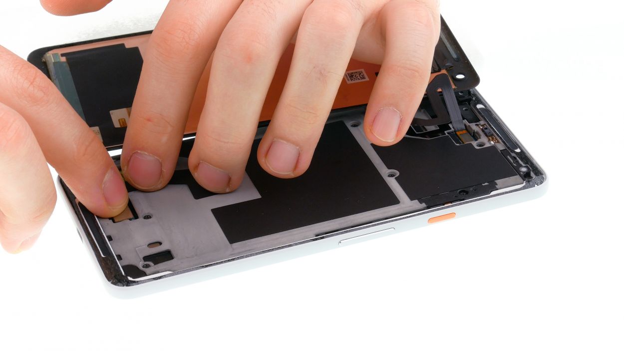
– Next up, grab a flat plastic tool and gently slide it into the tiny slot at the bottom right of the image. You’re doing great!
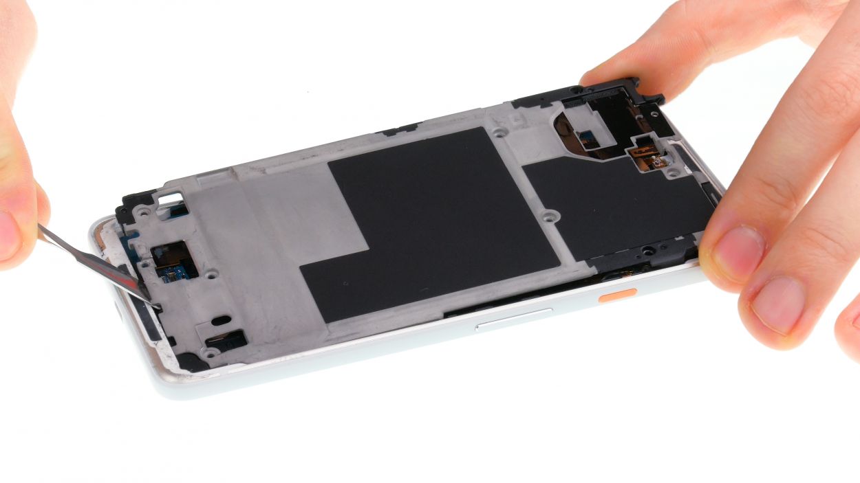
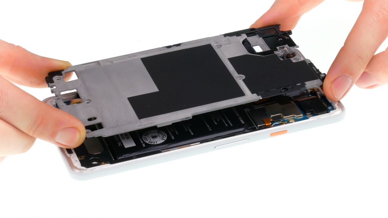
– Now, glide that tool around the device like you’re on a smooth dance floor, and then carefully remove the midframe. You’ll feel those clips popping free!
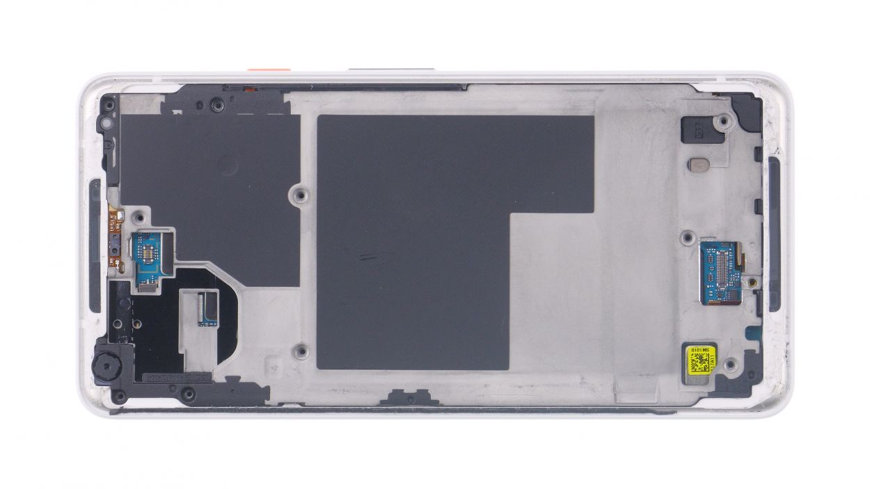
– Once all the clips are set free, you can easily lift out the midframe. Nice work!
Step 5
Grab those trusty plastic tools for all your electrical parts! Metal can be a bit of a troublemaker, scratching contacts and causing short circuits. Keep it cool and safe with plastic, and your repair journey will be smooth sailing. If you need help, you can always schedule a repair!
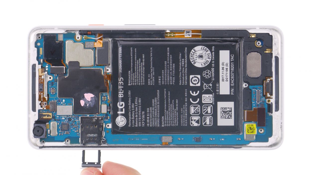
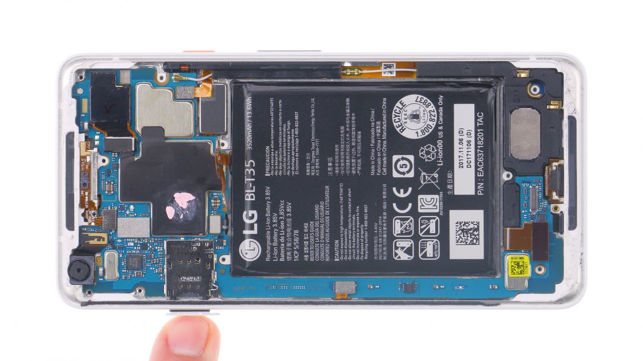
Step 6
– Pop that SIM tool into the tiny hole of the SIM tray and give it a gentle push.
– When the tray slides out, go ahead and pull it out with care.
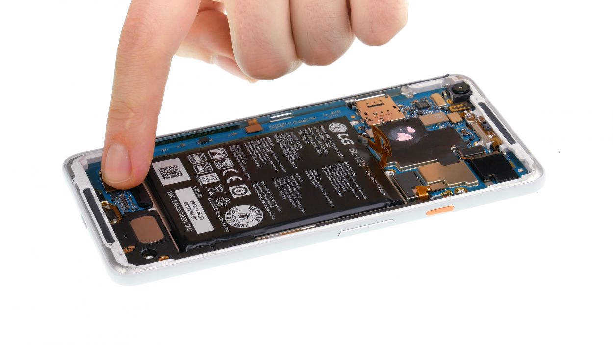
Step 7
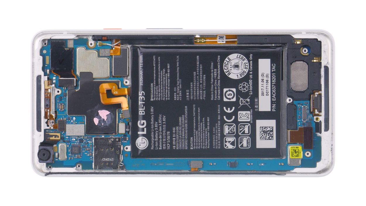
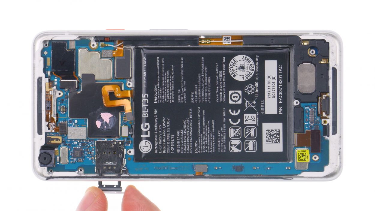
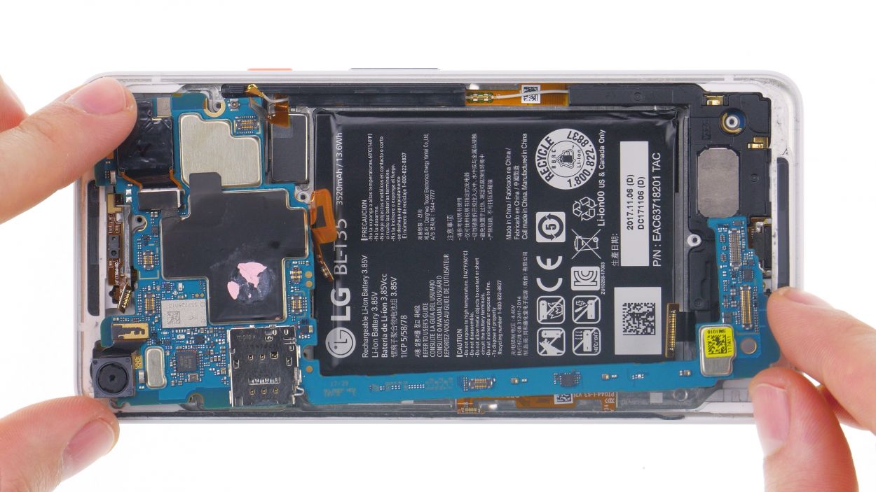
Antenna
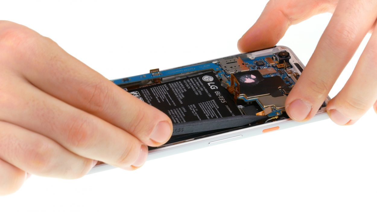
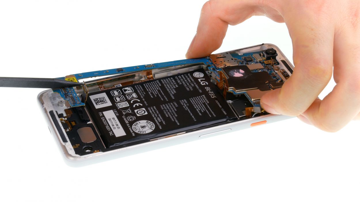
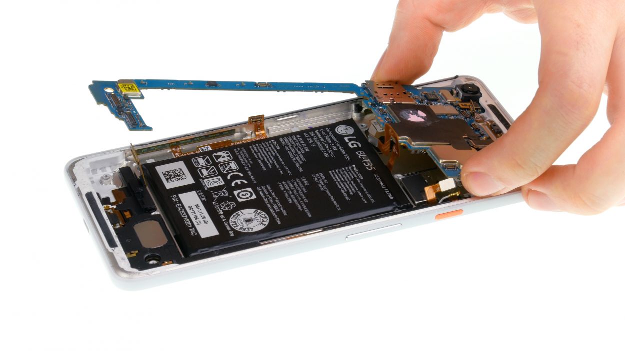
Whoa there, cowboy! That mainboard is long and skinny – like a supermodel! Gently lift it from different spots, then give it a little tilt to slide it out. Don’t yank it until you’re sure it’s completely free. If you need a hand, you can always schedule a repair.
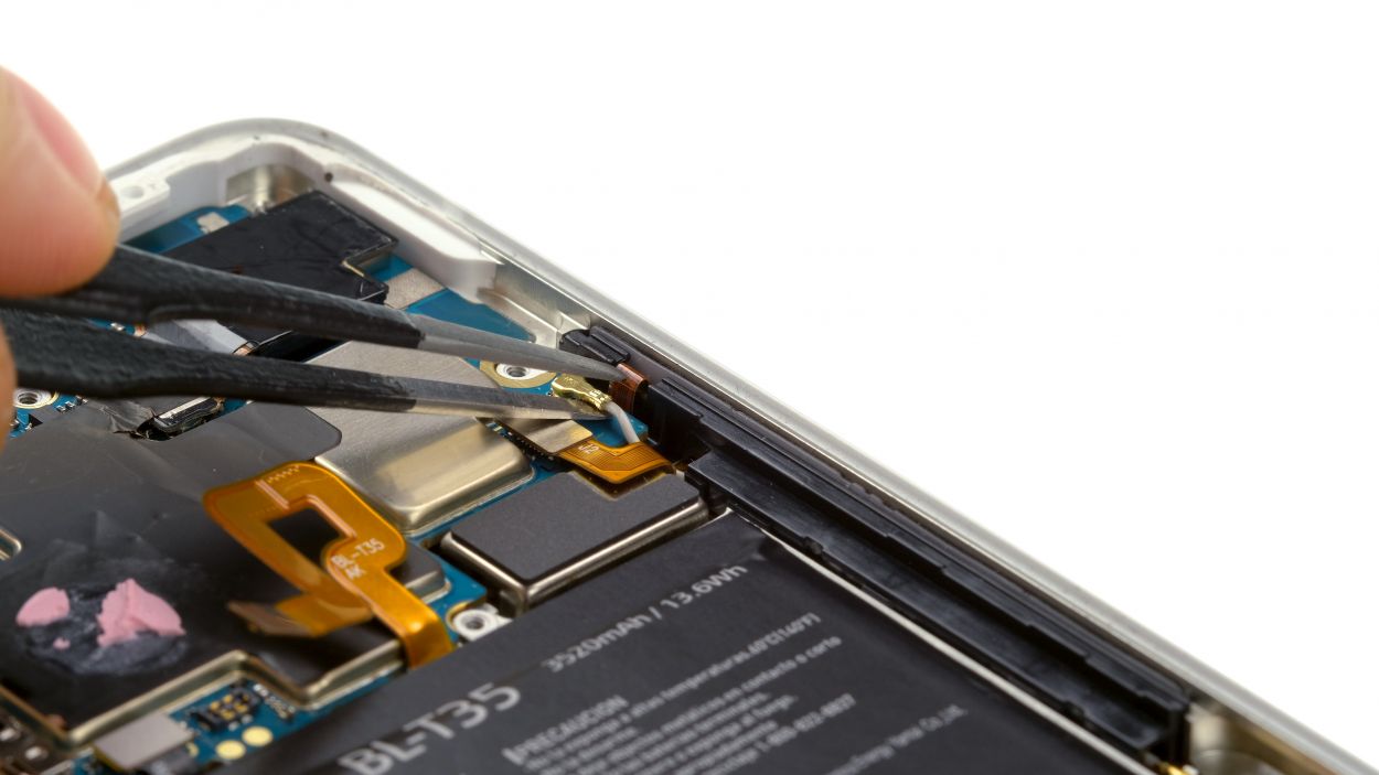
– Gently give the antenna plug a little twist with your tweezers, and it’ll pop right out.
– Unplug the connectors from the mainboard like a pro.
– Pry out the mainboard with ease! Just slide a pointed plastic tool into the inner corner and you’ll be golden.
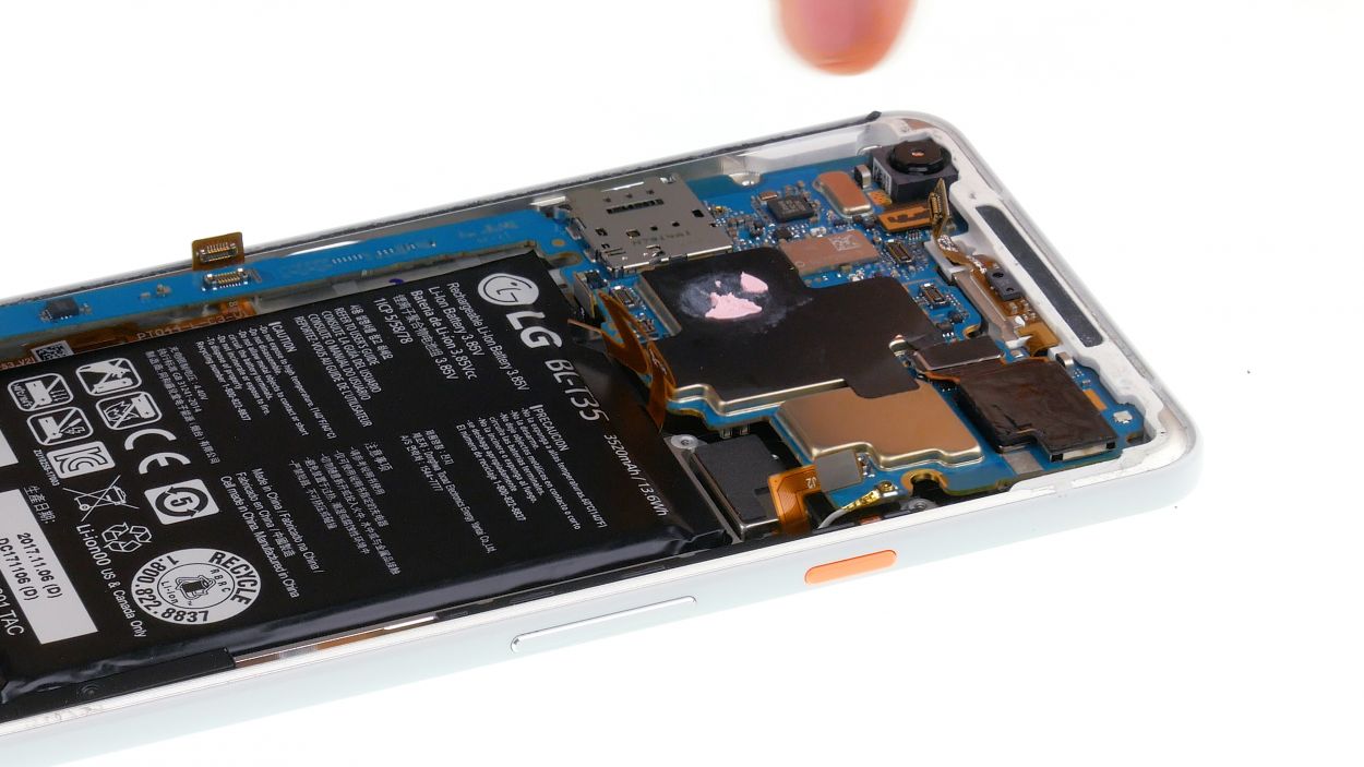
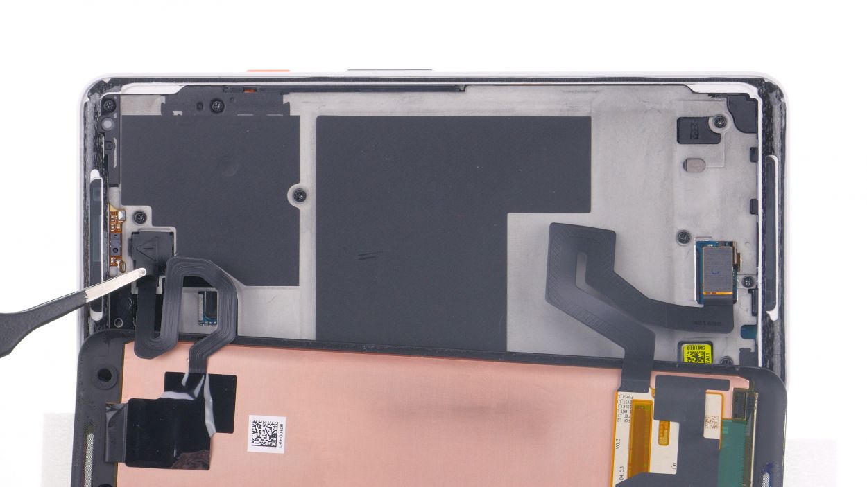
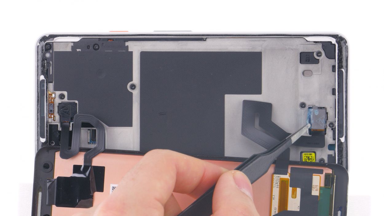
Step 8
– Use a plastic tool to pry out the speaker at the corner.
– Take the speaker out of the device.
Step 9
Antenna
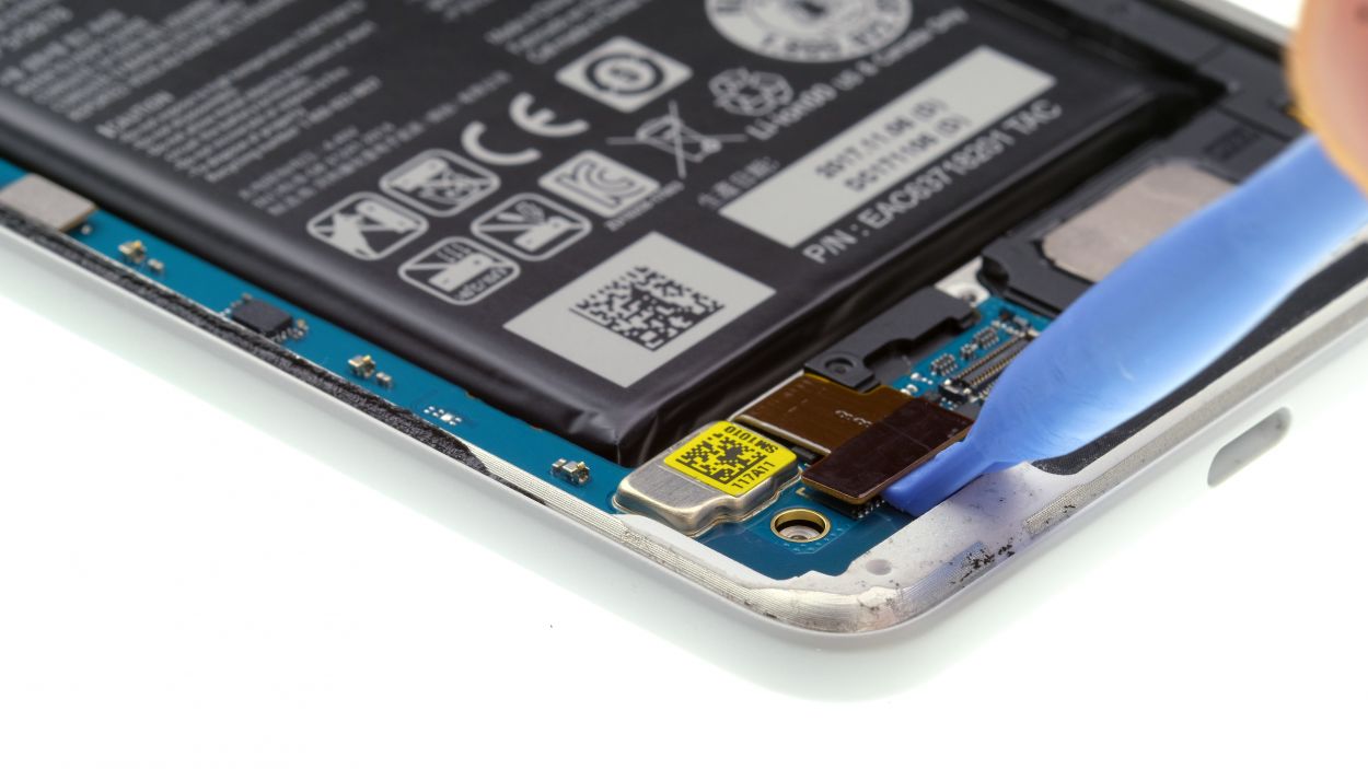
Handle with care—those USB cables can be a bit dramatic and snap at the slightest touch! Let’s keep everything in one piece.
– Handle the USB cable with care! It’s a bit of a delicate flower and can break easily.
– To start, disconnect the antenna cable plug. Just grab it by the plug and give it a gentle twist to free it up.
– Next, let’s warm up that USB flexible cable a bit to make the adhesive more forgiving.
– Carefully slide a flat tool under the flex cable and work your way along to remove it little by little.
– Watch out for the tricky part near the antenna plug—it has some serious glue action going on. Use a plastic tool to gently loosen the glue underneath the board.
– Time to say goodbye to the plastic holder of the microphone right next to the USB port. Once that’s off, you can peel the glued microphone out from the frame.
– Once you’ve got the entire USB flex cable loose, it’s smooth sailing from there—you can now remove it from your device!
Step 10
Antenna
– Slide in that USB flexible cable like a pro!
– Pop the microphone and USB port into their cozy spots in the frame.
– Gently press down on all parts of the flex cable to make sure they’re snug as a bug.
– Connect the antenna cable plug—grab the end sleeve with tweezers and give it a little push.
– Now, let’s get that microphone holder in place and give it a nice press to secure it.
Step 11

– Place the speaker in the device and press it in all around.
Step 12

Antenna
– Start by gently bending all the connectors to the side so they don’t get stuck under the board; we want everyone to have their space!
– Now, carefully insert the board into the device, giving it a light press to settle it in.
– Next up, connect those individual connectors on the main board until you hear a satisfying snap; that’s them saying they’re happy to be connected!
– Finally, position the antenna plug right above its socket and give it a gentle push to lock it in.
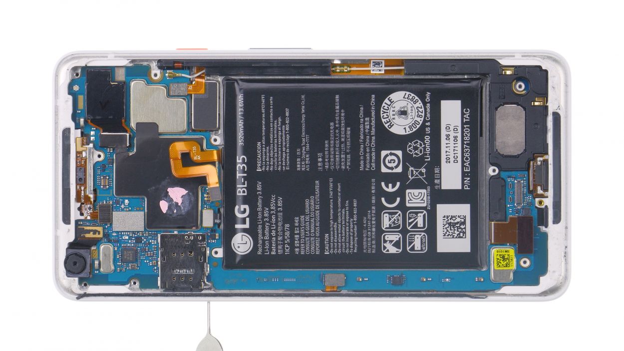
Step 13
If the tray isn’t sliding in smoothly, don’t go all Hulk on it! Take a moment to check if the logic board is snug as a bug in its place.
– Time to pop that SIM card back in! (If needed, of course!)
– Slide the SIM tray home. Easy peasy!
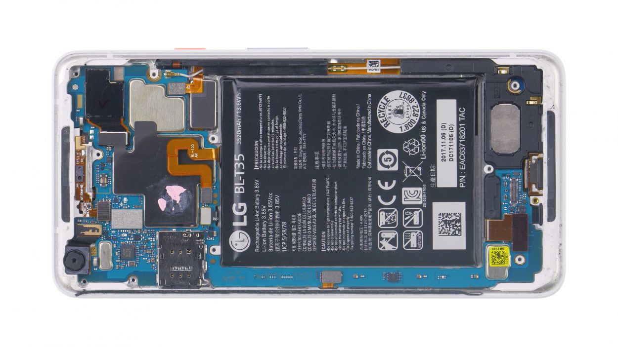
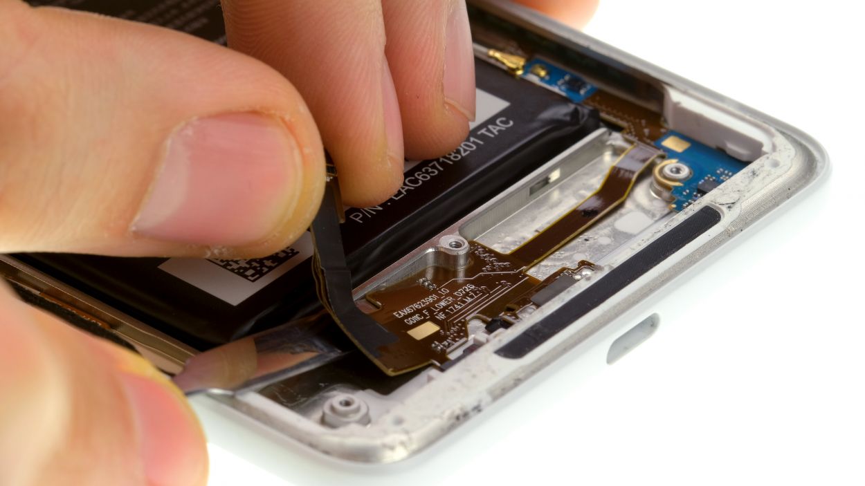
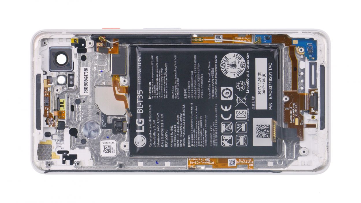
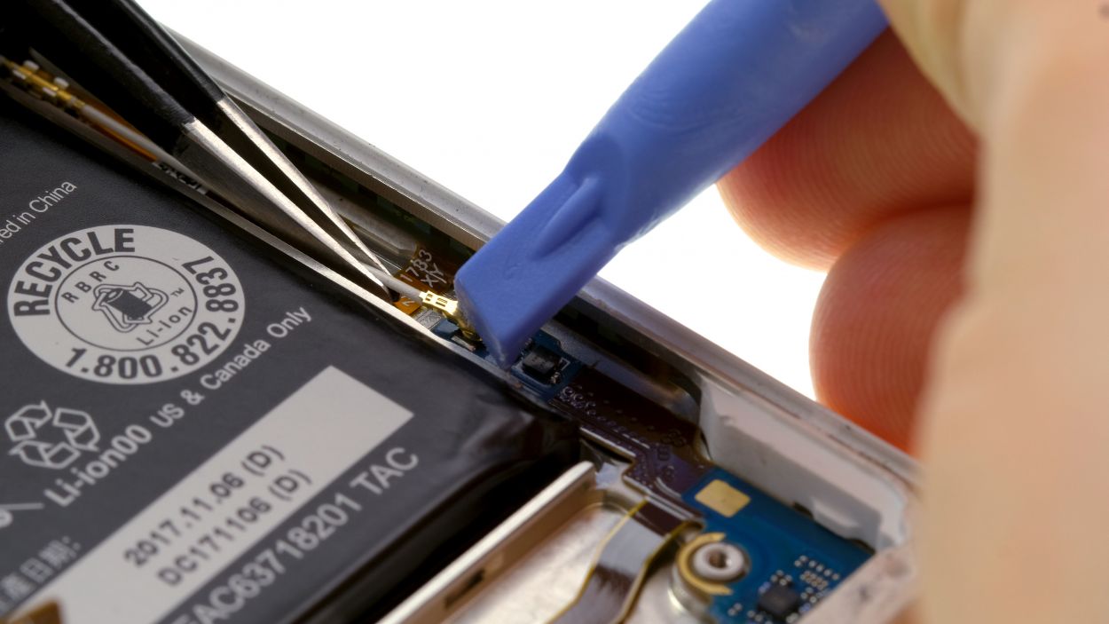
Step 14
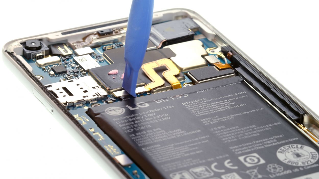
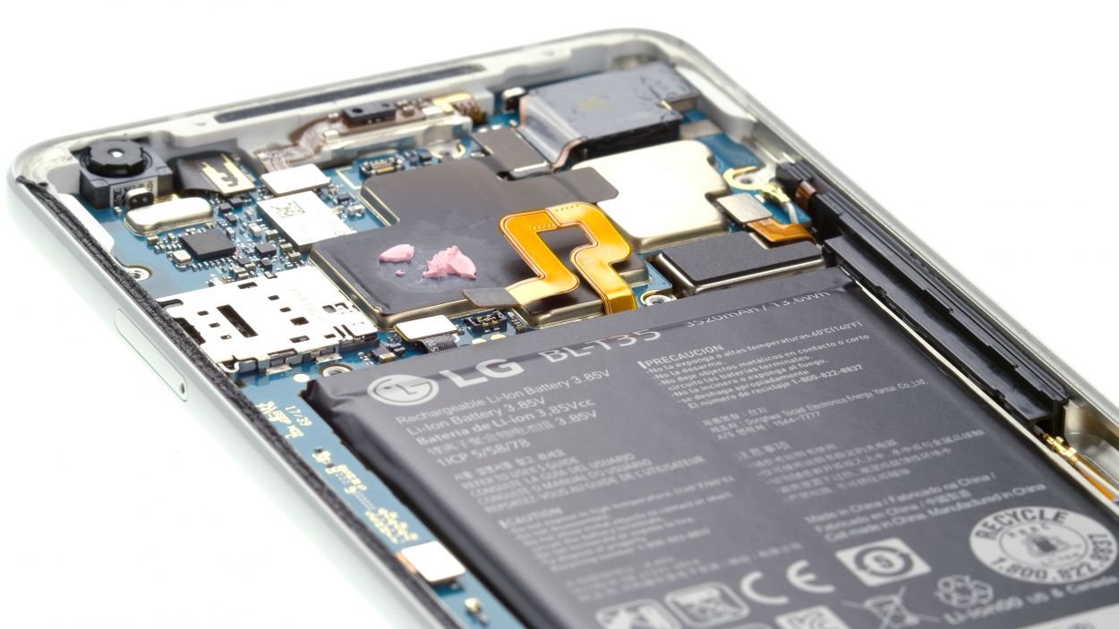
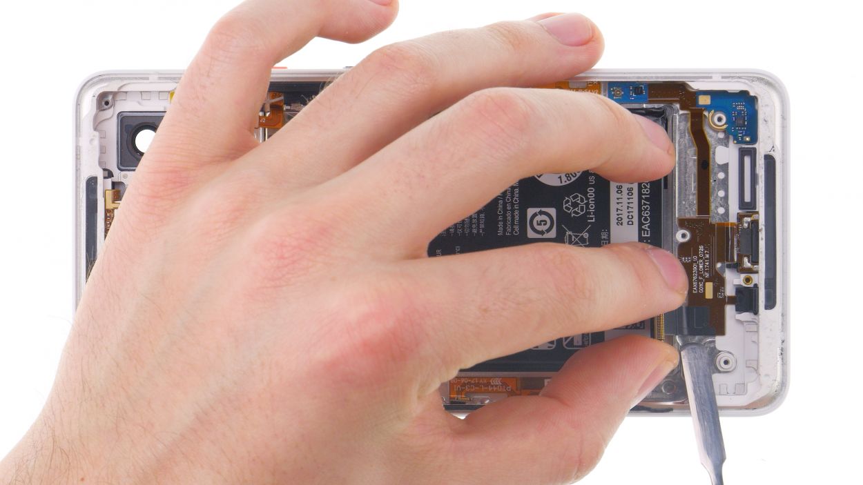
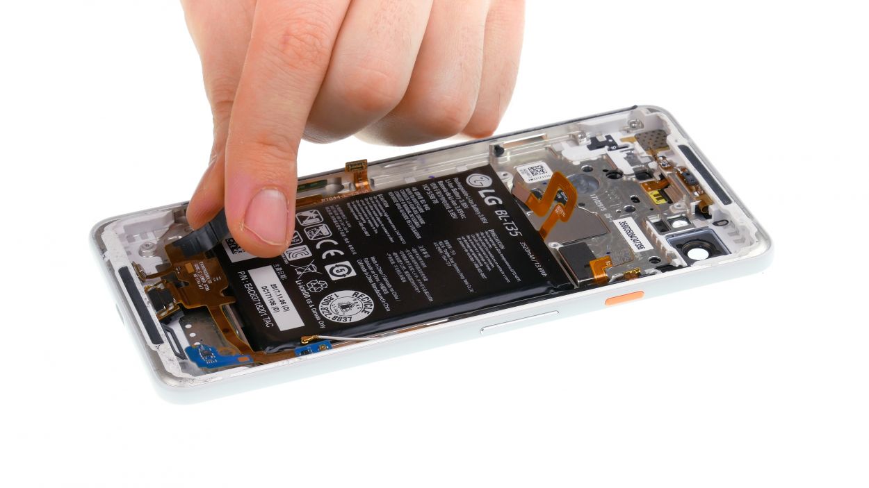
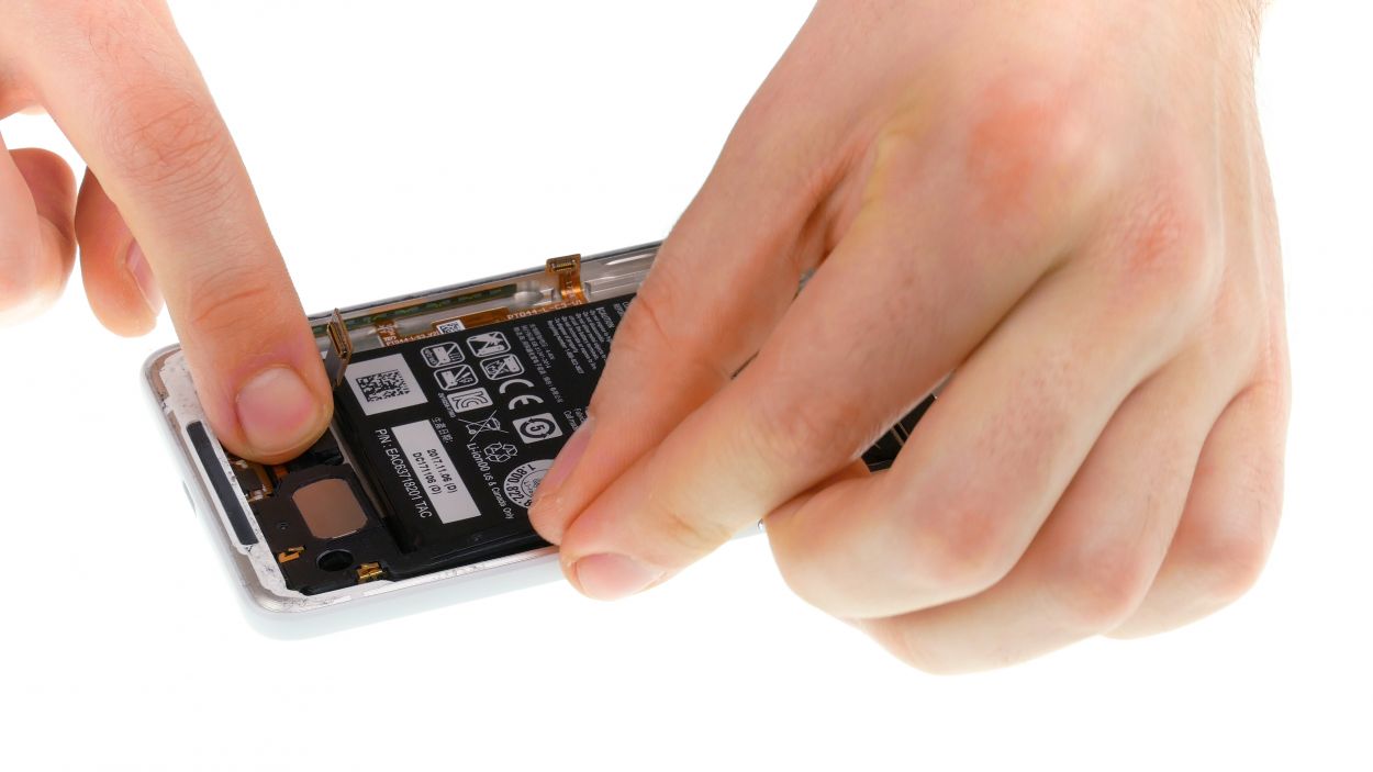
Battery connector
– Time to plug in that battery connector! Let’s get everything powered up and ready to roll.
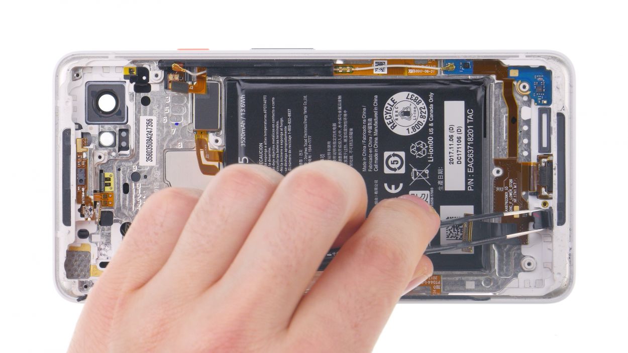
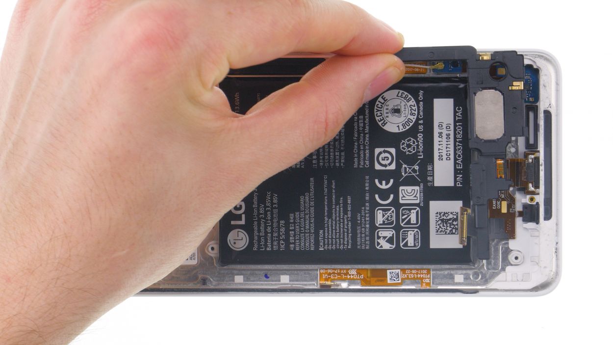
Step 15
11 × 2.7 mm Phillips
– Gently set the midframe into the device and give it a little press to secure it in place.
– Next up, grab those Phillips screws of the same length and fasten them all snugly.
Step 16
Hey there! Just a friendly reminder to keep those fingers safe – maybe throw on some gloves while you’re at it. Safety first, fun second!
– Gently scoop out every last piece of shattered glass.
Step 17
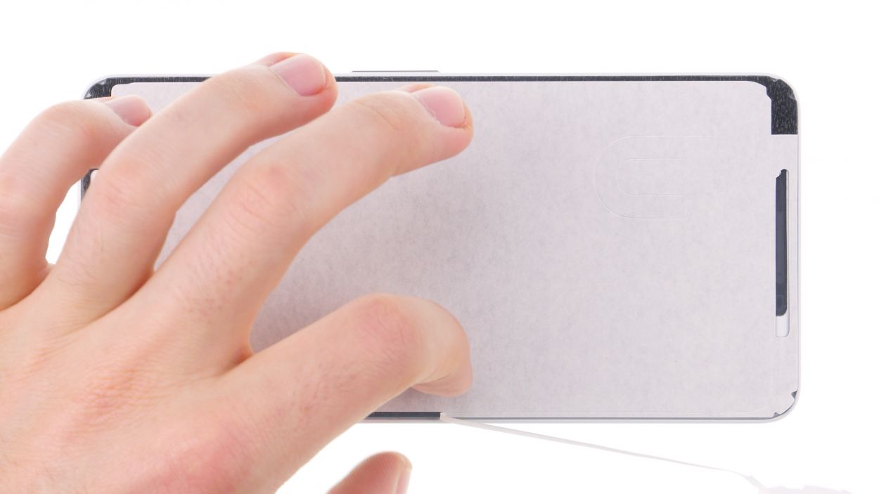
– Let’s get this show on the road! First, carefully place the frame sticker onto the display, leaving the backing film on for now – we’re just checking the alignment.
– The front camera hole is your best friend here; it’ll show you exactly which way the sticker should be facing.
– Time to peel off that outer backing film! Stick on the frame sticker with the blue film facing up. You got this!
The adhesive frame is super slim and can rip pretty easily, so take your time and tackle it step by step. You’ve got this!
P.S. If you’re giving your display a fresh start, make sure you’ve got a new adhesive frame waiting in the wings to keep everything snug as a bug on a rug! You can order one up before you kick off the repair adventure. If you need a hand, give us a shout. We’re always down to lend an ear (and a tool or two) to help you schedule a repair!
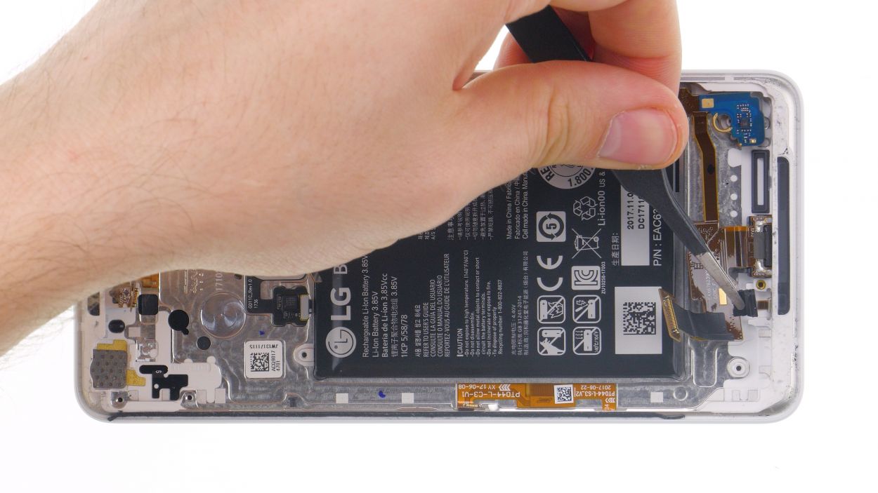
Step 18

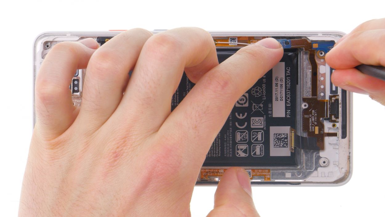
Display connector
– Reconnect those display connectors! Gently press the contact onto the motherboard connection until you hear that satisfying click.
– Now, let’s get those plastic covers back on! Press them into place and remember to attach the tape on the second cover. You’ve got this!
Step 19