Replace Liquid Metal PlayStation 5 Pro: Step-by-Step Guide
Duration: 45 minutes
Steps: 35 Steps
Ready to get a little hands-on with your PlayStation 5 Pro? This guide’s got your back for applying liquid metal like a pro! Whether you’re freshening up the existing liquid metal or doing a full-on makeover, you’re in good hands. Your PS5 Pro loves its Accelerated Processing Unit (APU) and the magic of liquid metal thermal interface material, which does a wonderful job of keeping things cool compared to standard thermal paste. But hey, just like any good thing, it might need a little TLC. If your console’s been standing tall for too long, the liquid metal might show signs of oxidation, looking a bit dried-out or cracked. No worries, you can clean it up and give it a new lease on life! If it’s just a bit uneven, a quick re-spread will have it back to even-steven in no time. And if you notice your PS5 Pro feeling hot under the collar, throttling or not performing as expected, it might be time for a liquid metal refresh – or check in on that fan of yours. Got a fan in need of a little spring cleaning? Follow along with this guide!
Step 1


Before you dive into this repair adventure:
– First things first—power down your PlayStation and unplug all those pesky cables and accessories. It’s time to give your console a little break!
– Now, let’s get that console all comfy. Remove any stands holding it up and gently lay it down with the right side facing up. We’re in for some good times ahead!
Step 2


The console cover is held in place by some nifty hooks at the back and clips at the front. Just a heads up, you’ll hear some cheerful ‘pops’ as those clips come loose!
– To tackle that cover, give the front edge a solid tug to pop those clips loose.
– Now, go ahead and lift off the cover.
Step 3


– Now that you’ve got one cover removed, use the same steps to take off the other three – it’s a breeze!
– To put a cover back on, simply align the hooks with their cutouts on the rear edge, then press the front edge firmly until the clips click back into place.
Step 4


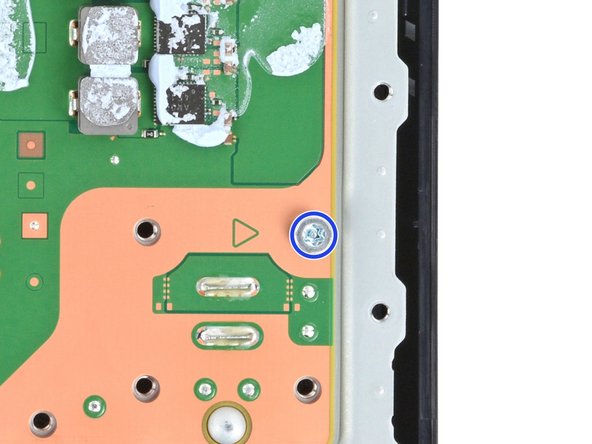
As you dive into this repair, be sure to keep tabs on every little screw! They all have their special spots, so let’s ensure each one finds its way back home after all the fun.
– Grab your trusty Phillips screwdriver and tackle that 17.1 mm long screw that’s holding the expansion slot cover in place. It’s time to set it free!
Step 5


– Gently pry open the expansion slot cover located near the notch by the screw hole using your fingers, then pop it off with care.
Step 6


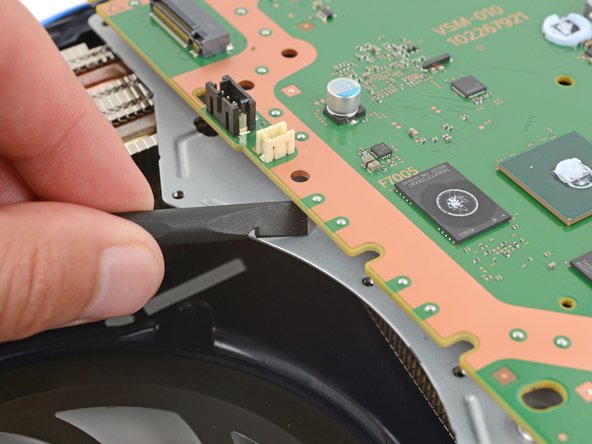
Don’t worry, the cover’s just holding on with a little bit of friendly adhesive. You’ve got this!
– Give those plastic covers a gentle nudge with your fingers to free up the fan cable connector hiding beneath. They can be a bit shy sometimes!
– When you’re putting everything back together, just press that plastic piece down firmly to make it snug with the leftover adhesive. If it acts rebellious and won’t stick, don’t worry—some strips of double-sided tape will do the trick!


Step 8


Need a little extra grip? Grab those cables just above the connector head and gently pull. You got this!

Step 9


– Grab your trusty T8 Torx Security screwdriver and get ready to remove the four screws holding the fan in place:
– First, you’ll find one 31.7 mm-long screw – take that out
– Next up, remove two 21.5 mm-long screws – those are the next to go
– Last but not least, take out one 11.5 mm-long screw and you’re all set


Step 11


If you’re in the U.S., good news! The Magnuson–Moss Warranty Act has your back and those pesky stickers can’t scare you. Just keep in mind that warranties can vary in other parts of the world. Stay savvy and keep smiling!
– A sneaky tamper-evident sticker is hiding one of the screws on the right side of the inner shell. Time to get it out of the way!
– Grab your trusty tweezers and carefully peel up the sticker to reveal the screw underneath. You’re making great progress!


Step 13


– Grab your trusty T8 Torx Security screwdriver and unscrew those 10 screws holding the right‑side inner shell in place:
– Four screws, 18.8 mm long
– Two screws, 18.6 mm long
– Four screws, 31.7 mm long
Step 14


– Time to give that right-side inner shell a little lift! Go ahead and pop it straight up and out of there. You’ve got this!
Step 15


If you’re stuck, gently rock the connector from side to side to loosen it. This should help it come free with ease.
– Grab those angled tweezers and give a firm squeeze around the sides of the CMOS board connector, making sure to hold them close to the connector for the best grip.
– Now, with a steady hand, gently pull the connector straight up and out of its socket to disconnect it. Easy peasy!
Tools Used

Step 16


– Gently lift the CMOS board off the small metal nubs with your fingers and pull it towards the center of your console – it’s like a little puzzle piece coming out. Once it’s removed, you’re one step closer to getting your device up and running.
– If your new board doesn’t come with a cable, don’t worry, just transfer the original cable to your replacement board. Easy peasy.
Step 17


– Ready to get this antenna cable party started? Let’s slip a spudger under the metal neck of one of those antenna cable connectors and gently lift it straight up to disconnect it.
– Now, repeat the process for the other antenna cable – let’s get ’em both disconnected!
– Alright, time to put things back together. During reassembly:
– Check the markings on the board – you’ll see a socket marked RB and another marked RW. Connect the blue cable to RB and the white cable to RW. We’re making sure everything’s in the right spot!
– To reconnect a cable, hold the metal connector head over its socket and gently press down with the flat end of a spudger until it clicks into place. No need to force it – if you’re having trouble, just reposition the connector and try again.
Tools Used


Step 19


– Gently maneuver those antenna cables away from their metal shield clips with your fingers—like you’re giving them a little vacation!
– Carefully guide the antenna cables over to the side of your PlayStation, making sure they’re comfortably out of your way.
Step 20


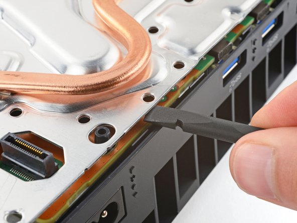
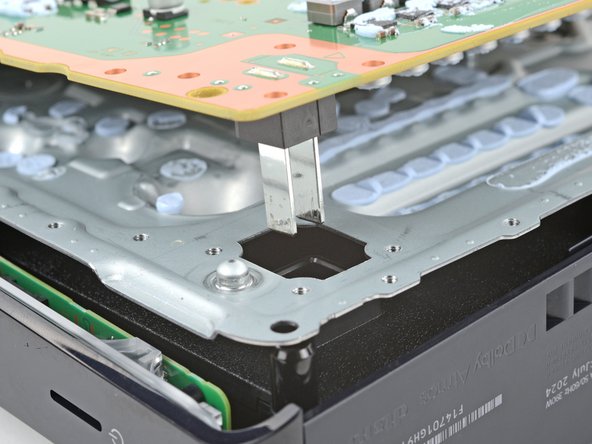
The thermal paste is like a strong hug between the bottom heat sink fins (the ones closest to the power button) and the metal shield. Over time, this hug can get a bit too tight, so be prepared to use some gentle yet firm persuasion to separate the heat sink – it might take a little effort, depending on how old your device is and how well the thermal paste is holding on.
– Slide the flat end of your trusty spudger under the bend in those copper pipes, right near the bottom edge of the heat sink.
– Gently use your spudger to lift the heat sink, applying some steady pressure to break it free from the thermal paste. You’ve got this!
– If the heat sink isn’t quite ready to part ways, don’t be shy—go ahead and pry up the bottom edge on the opposite side of those metal fins.
Tools Used
Step 21


Keep your paws off the sharp, metal fins on the heat sink!
Before you dive into the world of thermal paste removal, take a moment to snap a mental pic of where the old paste is hanging out and how much it has claimed on the metal shield. This little trick will help you nail the replacement job like a pro!
– Grab hold of the heat sink, holding it by its copper pipes, and give it a gentle lift to remove it.
– When putting it back together:
– Take the flat end of a spudger and scrape up any leftover thermal paste. Don’t worry, we’re getting rid of it all!
– Get rid of any lingering thermal paste and residue with high‑concentration (>90%) isopropyl alcohol and a microfiber cloth. A clean slate, right?
– Time to put on a fresh coat of thermal paste where the old stuff was.
– Give the heat sink a firm push back into its place. You got this!
Tools Used

Step 22
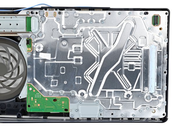

– Let’s get started by removing 39 screws using a T8 Torx Security screwdriver – it’s time to get hands-on!
– First, take out the thirty-three 7.5 mm-long screws that hold the metal shield plate in place – you’re making great progress!
– Next, locate and remove the one 11.5 mm-long black screw that secures the main board assembly – you’re doing fantastic!
– Now, remove the one 28.7 mm-long screw that keeps the interconnect cable cover in place – almost there!
– Finally, take out the four 7.5 mm-long screws that secure the interconnect cable cover – nice work!
Step 23

– Time to get that interconnect cable cover outta there!
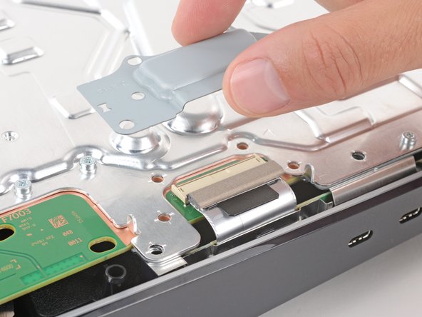
Step 24


– Grab that trusty spudger and gently press down the metal bar on the interconnect cable socket. You got this!
– While keeping that metal bar down, use your fingers or tweezers to clutch the plastic pull tab and smoothly slide the cable right out of its cozy socket.
– When it’s time to put everything back together, just pop the interconnect cable into the socket until you hear a satisfying snap. Easy peasy!
Tools Used
Step 25

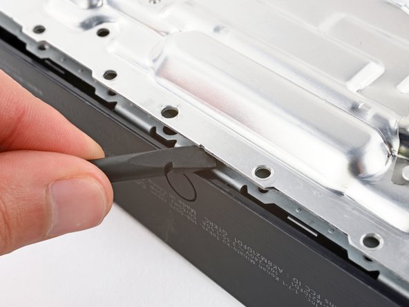
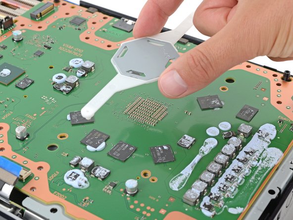
Thermal pads keep the top shield plate snugly attached to the main board. Depending on how long your device has been around and the condition of those pads, you might need to channel your inner superhero to pry that plate loose!
– Now, let’s gently separate that top shield plate. Take your trusty spudger (that flat-ended tool) and slide it in between the plate and the main board. Give it a little pry to get things moving. Work your way around the whole perimeter, prying carefully until you hear that satisfying ‘pop’ and the plate comes right off. You got this!
Tools Used
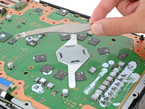
Step 26
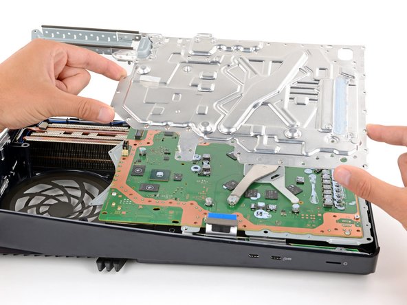

Make sure your replacement pads are the same thickness as the originals! If not, you might find the foam around the APU isn’t sealing quite right. Let’s keep everything snug!
– Let’s lift that top shield plate right off! It’s like giving your device a little makeover.
– While we’re here, take a quick peek at those thermal pads on the top of the main board. They might need a little TLC. Just make sure they’re snuggled in between the top shield plate and the main board—no need for them to get lost!
Step 27
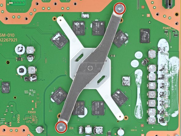

Try not to tackle one screw at a time, or you might accidentally give your APU a little too much drama. When disassembling and reassembling, keep it cool by alternating between the two screws, turning each one just half a turn at a time. This way, you’ll keep even pressure on the bracket and avoid any surprises along the way!
– Grab your T8 Torx Security screwdriver and let’s get to it! You’ll need to unscrew the three pesky screws that are holding the main board in place:
– First up, tackle those two 16.3 mm long screws that are keeping the APU tension bracket snug as a bug.
– And don’t forget that one 7.5 mm long screw – it’s just as important!
Step 28

– Gently lift off those APU brackets from the board—time to set them free!
– Now, as you get ready to put it all back together:
– Start with the bracket that has the plastic arms; make sure those pegs slip right into their cozy cutouts.
– Once that’s in place, bring on the metal bracket and set it on top—ensure they’re stacked just right, making sure the screw holes align perfectly.
Step 29

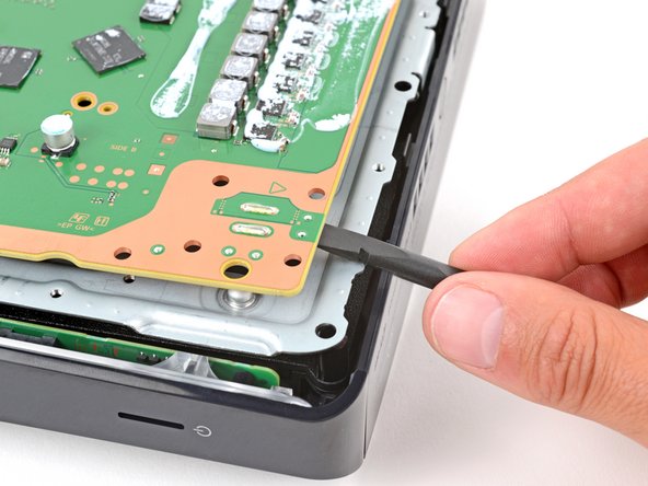
Be careful not to completely remove the motherboard just yet — there are still some metal prongs holding it in place near the power button, and we’ll take care of those in the next step.
– Gently slide the flat end of a spudger under the main board, right by the fan’s cozy recess, and give it a little twist to free the board. Think of it as getting a stubborn sandwich out of a tight container!
– Now, let’s keep that momentum going! Move around the edges and repeat the twisting magic at various points to fully liberate that board. You’ve got this!
Tools Used
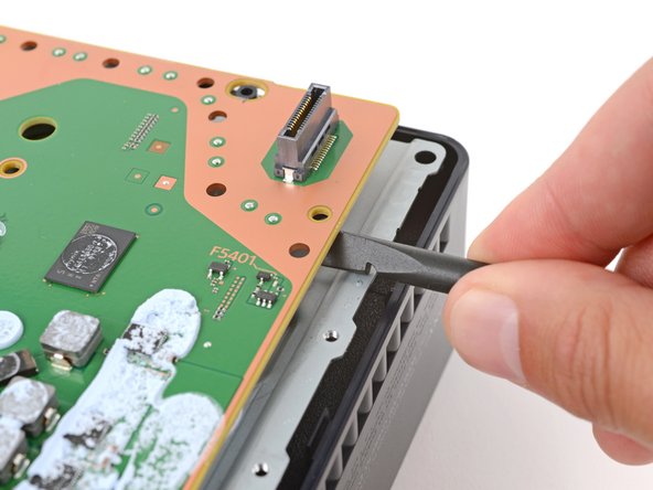
Step 30

The power supply is attached to the main board with metal prongs that plug into the corner near the power button.
You’ll feel those prongs slide out, no problem!
– Let’s get started by carefully inserting the flat end of a spudger between the bottom edge of the board and the lower shield plate, right next to the two parallel solder joints near the corner with the power button.
– Now, use your trusty spudger to gently pry up the board until the two prongs come completely out of their socket – it’s like a little puzzle piece coming together!
– When you’re putting everything back together, press down on the corner of the board to fully seat the prongs in the power supply. You should feel them slide into place nicely, and that’s a great feeling!
Tools Used
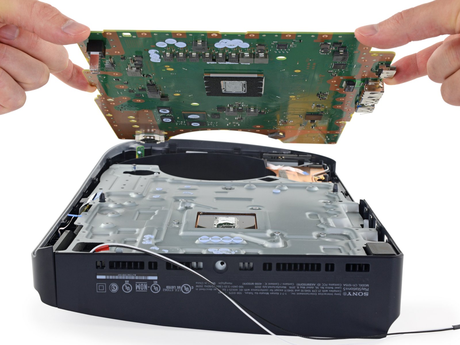
Step 31
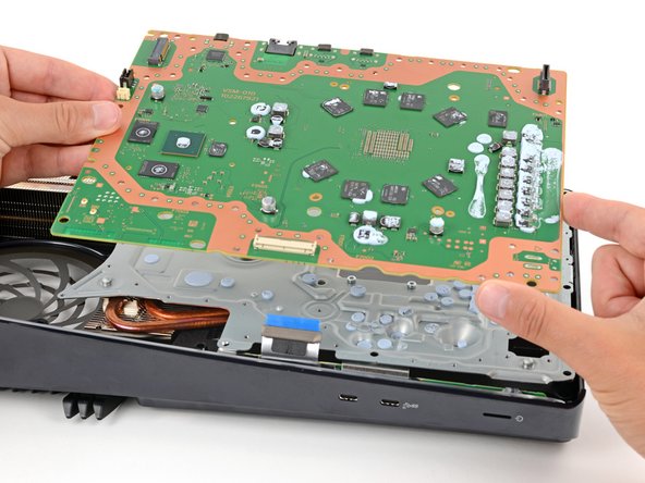
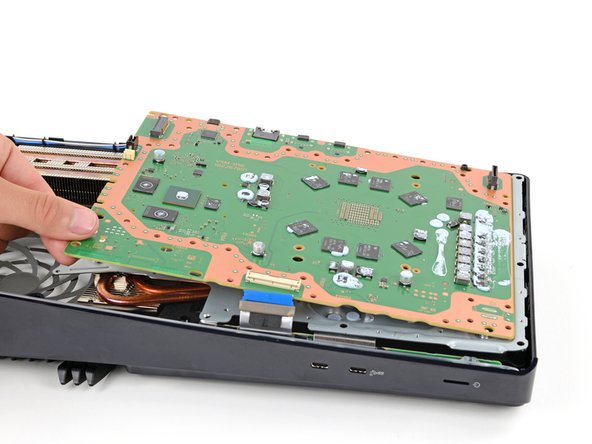

Hey there, champ! Be super careful when handling the board. Don’t press it against your work surface – you might end up hurting those delicate components. Take it easy and we’ll have this thing fixed in no time!
– First, carefully remove the main board and flip it over, taking a moment to lay it on a clean work surface with the APU facing up – nice and easy!
– During reassembly, remember to keep all cables connected to the board out of the way, so they don’t get trapped underneath – let’s keep things tidy!
– Next, carefully flip the board over, making sure the APU is now on the bottom, and be gentle so you don’t spill any liquid metal – we’re almost there!
– Finally, keep the board level and gently lower it into place, and you’ll be done with this step in no time – great job!
Step 32
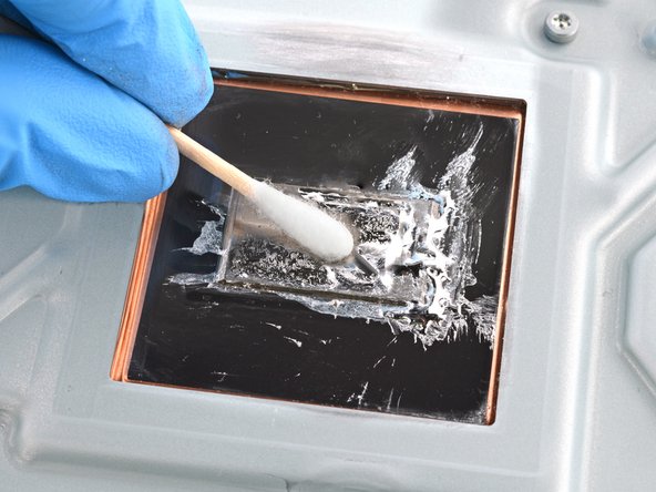

Pop on some gloves to keep that liquid metal from giving you a surprise.
Handling the liquid metal can be a bit of a challenge—it spreads and smears quite easily. Grab some fresh cotton swabs and dab more alcohol as needed.
The surface needs to be squeaky clean for the new liquid metal to do its magic.
– Got a disposable syringe? Use it to scoop up those pools of liquid metal, but keep the fresh liquid metal out of that syringe!
– Let’s start with the heatsink: drip a bit of 90% or higher isopropyl alcohol onto a cotton swab and give that heatsink surface a good cleaning.
– Use the same process to make sure you get every bit of that liquid metal residue off.
– And let that heatsink dry completely before moving on.
Tools Used

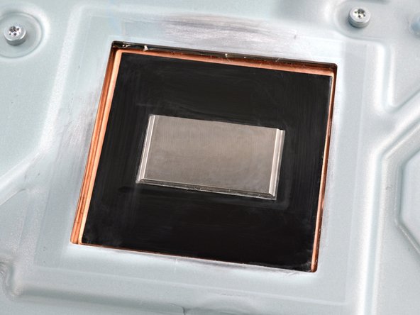
Step 33


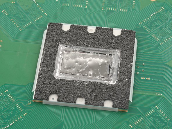
Heads up! Keep that liquid metal away from the board. It’s like a tiny, super-conductive puddle of trouble. The foam barrier will keep it in line, but it’s always best to be safe.
Double-check those replacement pads! They need to be the same thickness as the originals, or the foam around the APU might not seal properly. We don’t want any leaks!
Hey there, this foam barrier is like the APU’s little buddy, so let’s leave it where it is. No need to mess with it! We’ll get this repair done with all the right moves.
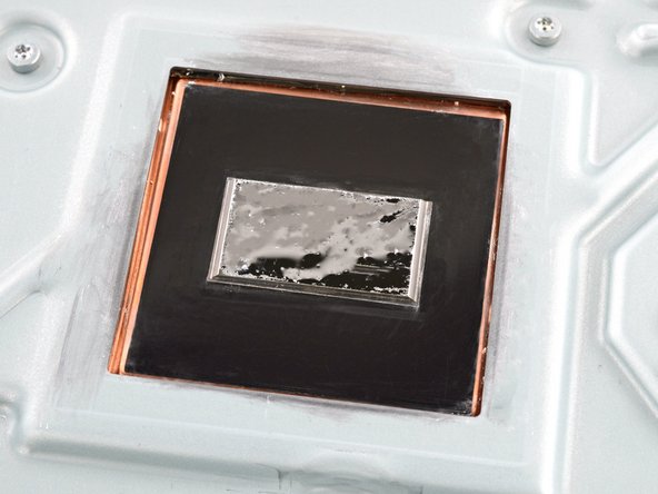
– Just like with the heatsink, make sure to clean and wipe off all the old liquid metal and its residue from the APU.
– Now’s a great time to swap out any thermal pads on the bottom of the main board if needed. They might be stuck to both the bottom shield plate and the main board.
Step 34

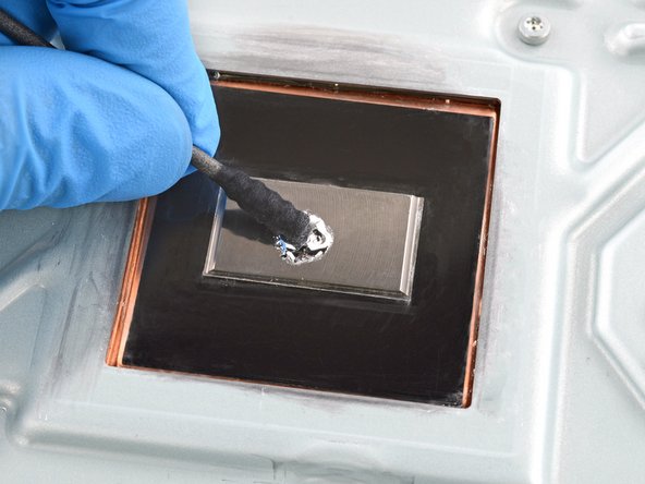
Got multiple applicator heads on your liquid metal syringe? Pick the one with the tiny, needle-like tip!
– Drop a tiny dab of liquid metal onto the heatsink—avoid the APU—think of it as the size of a matchstick head.
– Grab the spreader that came with your liquid metal or a clean cotton swab, and gently press down while spreading the metal evenly across the whole surface.
– If you spot any extra liquid metal hanging out, just use the syringe to suck it back up.
Step 35

You should still have some liquid metal left on your cotton swab from the previous step – perfect!
The main board is now all set for reassembly. You’re making great progress!
– Now that you’ve conquered this repair, you can put your device back together – just go in reverse order, starting with this step!
– If you’ve got any old tech lying around, be sure to send it to an R2 or e-Stewards certified recycler – they’ll give it a new life!
– Didn’t go as smoothly as you hoped? Try some troubleshooting tips, or ask the Salvation Repair community for help – we’re always here to lend a hand! schedule a repair
– Cancel: You didn’t finish the repair, but that’s okay – we’re here for you if you need help with anything! schedule a repair
–