Replace Mac Pro Front Fan Assembly 2006-2008 (First Generation) – DIY Guide
Duration: 45 minutes
Steps: 17 Steps
Time to tackle the Front Fan Assembly on your Mac Pro (Early 2008). Get ready for a smooth fix with a bit of patience and a can-do attitude. If you need help, you can always schedule a repair.
Step 1

The hard drives need to have these specs:
– Type: Got a Serial Attached SCSI (SAS) or a Serial ATA (SATA) 3 Gb/s? You’re in the right place!
– Width: Rocking a sleek 3.9 inches (102 mm)
– Depth: Depth of 5.7 inches (147 mm) – just right
– Height: Tall enough at 1.0 inch
Step 2

Heads up! If you’re adding SAS drives to a Mac Pro (Early 2008), you’ll also need to pop in the optional Mac Pro RAID Card. If you need help, you can always schedule a repair.
Step 3

Heads up! Make sure the latch on the back panel is in the up position. When it’s down, those hard drives and carriers are locked tight, and you won’t be able to pop them out. Keep it up and let’s get to work!
– Alright tech wizard, before you dive in, pop open the computer and lay it on its side with the access side facing up. Let’s do this!
Step 4

– Make sure the latch on the back panel is up, so the drives and carriers are unlocked.
– Slide the hard drive out of the drive bay.
Step 5

Heads up! When you’re handling the drive, make sure to grip it by the sides. We want to keep those delicate circuit board components safe and sound, so avoid touching the bottom, okay?
Just a quick tip: Gently slide the carrier and drive along the guides and into the drive bay. You’ll know you’ve done it right when you hear the satisfying click of the drive locking into place!
– Ready to swap out that hard drive? First, let’s get those four screws off that are holding the old drive to the carrier. Once they’re out, pop in the new drive and secure it in the carrier. You’ve got this!
Step 6


– Here’s the lowdown on getting that card out: First off, you’ve got two types of cards you might be dealing with—your standard card and one with a booster cable. Before you start pulling out either type, though, you’ve got to loosen up the two captive screws holding the PCI bracket to the enclosure. Then, take off the bracket. Need help? You can always schedule a repair.
Step 7

Treat that card like a prized possession! Only grab it by the edges, and steer clear of the connectors and components. When it’s time to remove it, lift it straight up from the connector—no wiggling allowed! When reinstalling, make sure to slide it straight in without any side-to-side shenanigans. Once your new card is snug in place, give it a gentle tug to make sure it’s all good. If you need help, you can always schedule a repair.
– 1) Give that little locking clip at the front of the card’s logic board connector a gentle nudge upward toward the media shelf to release it.
– 2) With a firm grip on the top corners of the card, lift it up and slide it out of its cozy expansion slot.
Step 8


Some graphics cards might need one or two booster cables to connect the card to the auxiliary power connectors on the logic board. No biggie!
For the NVIDIA GeForce 8800 GT, just one booster cable will do the trick, while the NVIDIA Quadro FX 5600 likes to have two. Easy peasy!
If you’re swapping out a booster cable for a shiny new one, simply disconnect it from the card and you’re on your way!
– Time to say goodbye to those booster cables! Unplug them from the logic board with ease.
– Next up, let’s set that small locking clip free! Give it a gentle push upward toward the media shelf to release it from the card’s logic board connector.
– Now, grab the card by its top corners and with a gentle tug, lift it up and out of its cozy expansion slot. You’ve got this!
Step 9

Booster Cable Tip for One Cable: Make sure to hook up your card’s booster cable to the right auxiliary power connector on the logic board. PCI slot 1 card? Connect to the lower connector. PCI slot 2 card? Upper connector’s your match.
Booster Cable Tip for Two Cables: Connect both cables to the two auxiliary power connectors. Need help? You can always schedule a repair.
Step 10

Heads up: The total power draw from all four PCI Express slots should stay under 300 W. Keep it cool and carry on!
Removing graphic cards? No sweat! The process for PCI Express Cards is pretty much the same, with just a few minor differences between the cards. You’ve got this!
Step 11


Heads up! The heatsink cover is secured with a few tabs and some sneaky magnets on its underside. Make sure to gently release those tabs before you can pop that cover off the enclosure!
– Don’t forget to double-check that all the PCI Express cards are safely tucked away and ready for their next adventure.
– Slide your fingers under the edge of the heatsink cover closest to the logic board. Gently lift it up towards the media shelf to pop those tabs and magnets loose from the top side of the cover.
– With your fingers still holding the bottom lip of the cover, lift it straight up to free the remaining tabs and magnets from the front side of the cover.
– Now, go ahead and remove the cover from the enclosure like a pro!
Step 12

Hey there! When you’re popping that processor heatsink cover back in place, be sure those sneaky tabs on the bottom match up perfectly with the slots below them. (FYI: The slots are hanging out on the front fan and memory cage, flanking the heatsink cover.) If you need help, you can always schedule a repair.
Step 13

– Hey there! Before you dive into removing the Front Fan Assembly, make sure to pop out the first two bays of the hard drives and safely stash away all PCI express cards. We want everything cozy and secure!
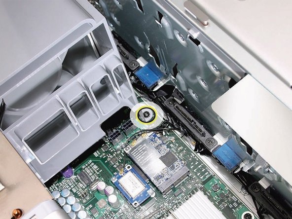
– Now, grab your trusty long-handled, magnetized #1 Phillips screwdriver and gently unscrew the top rear fastener of the front fan assembly. This little guy keeps everything snugly attached to the logic board, so take your time!
Step 14

– Take out the second Phillips screw from the bottom front of the assembly. If you need help, you can always schedule a repair.

Step 16


Replacement Note: Before you pop that front fan assembly back into the enclosure, double-check that those fan cables are cruising smoothly in the fan channel.
Replacement Note: Give a little wave to all AirPort and Bluetooth antenna wires, making sure they’re out of the way before you gently lower the fan assembly onto the logic board.
Step 17

– Replacement Note: Don’t forget to check that the latch on the upper left inside edge of the fan assembly clicks nicely into the slot on the inner lip of the enclosure. You’ve got this!