Replace Microsoft Surface Laptop 4 Headphone Jack
Duration: 45 minutes
Steps: 47 Steps
Get ready to tackle the headphone jack replacement on your Microsoft Surface Laptop 4 (15-inch)! If you notice your battery is looking a bit puffy, make sure to handle it with care. Some of the photos in this guide might be from a different model, so they could look a tad different, but don’t worry—they won’t mess with the steps you need to follow. If you need help, you can always schedule a repair.
Step 1


Before you start, make sure your laptop’s battery is below 25% charged. This is an important safety precaution – a charged battery can be a fire hazard if it gets damaged during the repair process.
– Disconnect all cables and power down your laptop completely.
Step 2


– Gently close the screen and flip your laptop over so the rear case is facing up. This will give you access to those sneaky four rubber feet waiting to be uncovered.
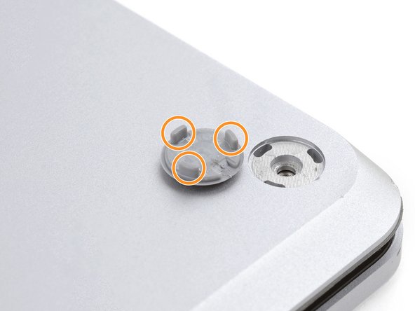
Step 3


Each foot has a little groove that makes it easier to pop it off the laptop!
– First, locate the back feet recesses – they’re the ones closest to the edge of your laptop, where the back meets the rest of the computer.
– Next up, find the front feet recesses – these are the ones nearest to the front edge of your laptop, where you’ll likely find the keyboard and other ports.
Step 4


The feet pop out super fast—watch out, or they might go flying!
– Slide one arm of your tweezers into the little nook of one of the feet.
– Give your tweezers a twist and pop it up to loosen the adhesive and unclip the foot from the laptop.
– Lift the foot off and set it aside.
– Rinse and repeat for the remaining feet.
Tools Used

Step 5

– This laptop has two types of feet. When putting it back together, make sure each foot finds its cozy little home.
– Give those feet a nice press into their spots to keep them snug on the frame.
– The rear feet have one single clip right in the center.
– The front feet have three clips and can only be fitted in one way.
– If the feet no longer stick to the frame, remove the old adhesive and use a bit of Tesa Tape where the old adhesive was.
Step 6


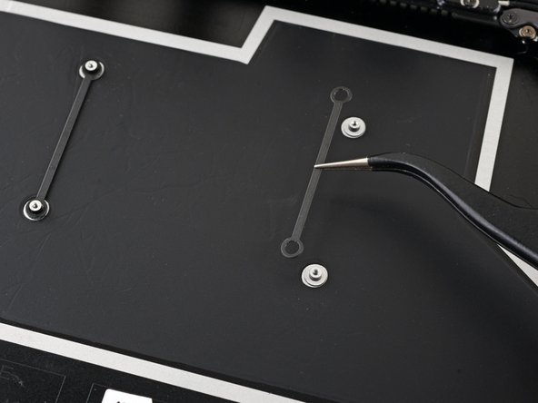
– Got some worn-out or busted feet? Grab those 8 mm rubber furniture pads:
– Peel off the backing of a pad.
– Line up the pad over the foot cavity and press it down to stick it in place.
Step 7

These screws can be a bit tricky! Keep a steady downward pressure to avoid any stripping mishaps.
Make sure to track every screw and return it to its original spot.
– Grab your trusty T5 Torx driver and unscrew the four 3 mm screws holding the upper case in place. You’ve got this—easy peasy!
Step 8


– Flip your laptop over and open the screen all the way. Let’s give this laptop a proper stretch!
Step 9


Hey there! Just a friendly reminder: don’t go all out trying to yank off the upper case—it’s still hanging on by a cable. Let’s keep it together!
Make sure the upper case is snug all around the edges. If there’s any space between the upper and lower case near the screen, it could lead to some screen drama when it closes. Let’s avoid that!
The top cover stays put thanks to some trusty magnets.
– Grab hold of the top edge of the upper case above the keyboard and pull straight up to pop it off.
– Gently lift the bottom edge of the upper case upward and away from the laptop, being careful not to tug on the ribbon cable underneath.
– When putting it back together, carefully lower the upper case onto the lower case, let the magnets snap it into place, and make sure it sits flat.
Step 10

The cable connecting the keyboard and touchpad to the upper case is like the lifeline of your laptop. Keep it snug and secure for a smooth typing and navigation experience!
– Slide the pointed tip of a spudger under one side of the magnet connector and gently lift it up to disconnect it.
– To reconnect, position the magnet connector over its socket with the cable facing down. Simply press down on the connector until it clicks into place.
Tools Used

Step 11

– Flip the upper case over so the keyboard side is facing down, and place it gently on a clean surface—time to give it the spa treatment!
Step 12

With the screw out, the SSD pops up at a cool angle.
– Grab your T5 Torx driver and unscrew that 2.7 mm screw holding your SSD in place. You’ve got this!
Step 13


Avoid yanking it up at a sharp angle—it’s a no-go! Doing so might just ruin the SSD and its cozy little socket.
Taking out the SSD? It’s like giving your battery a little vacation!
– Gently yank the SSD out of its cozy socket.
– When putting things back together, slip the SSD in at a slight angle.
Step 14


– Peel off the two pieces of black tape that are snugly hugging the bottom left and bottom right corners of the motherboard. They’ve done their job, but it’s time for them to take a break!
– Set the tape aside for now; it’ll be your trusty sidekick during reassembly.
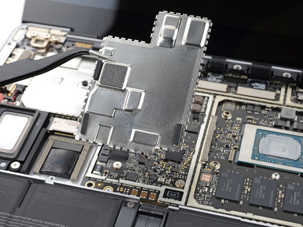
Step 15

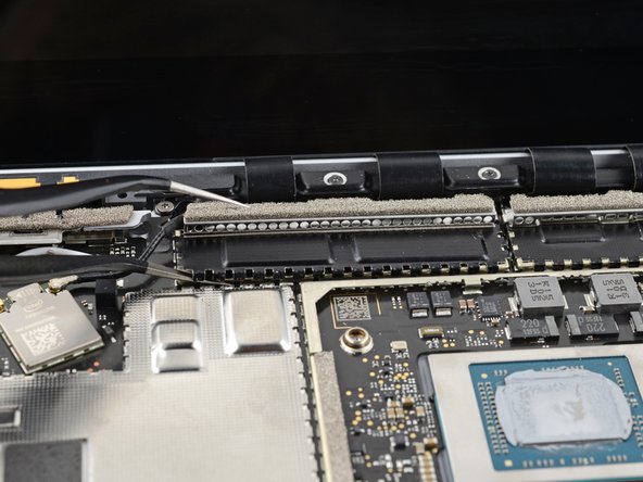
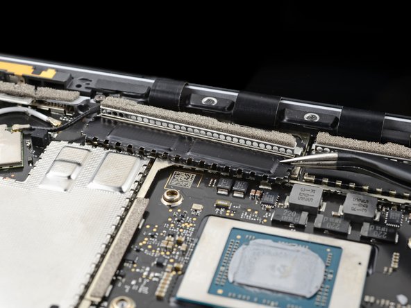
Try to keep the shield looking sharp—you’re going to pop it back in later during reassembly.
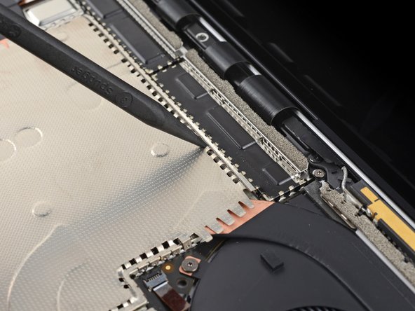
– Slide the pointed end of your trusty spudger into one of those little gaps at the top edge of the heatsink shield.
– Gently nudge it up to pop those clips free and let the shield breathe.
– Keep that groove going along the right edge just like before!
– Now, take one arm of your tweezers and slip it under the bottom right edge of the heatsink shield.
– With a gentle lift, release the last of those pesky clips.
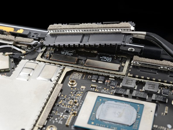
Step 16

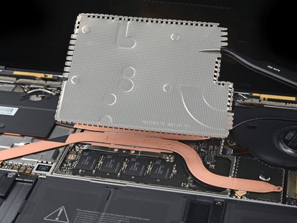
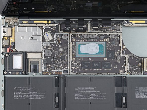
– Time to take off that heatsink shield! Let’s get it out of the way so we can see what’s cooking underneath.
– When you’re ready to put that shield back, just give it a good press around the edges to snap those clips back in place. You’ve got this!
Step 17

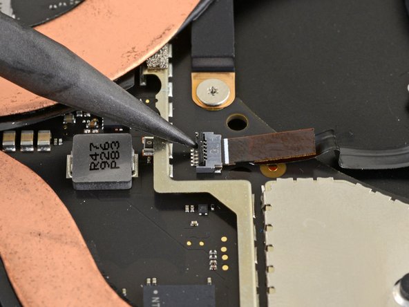
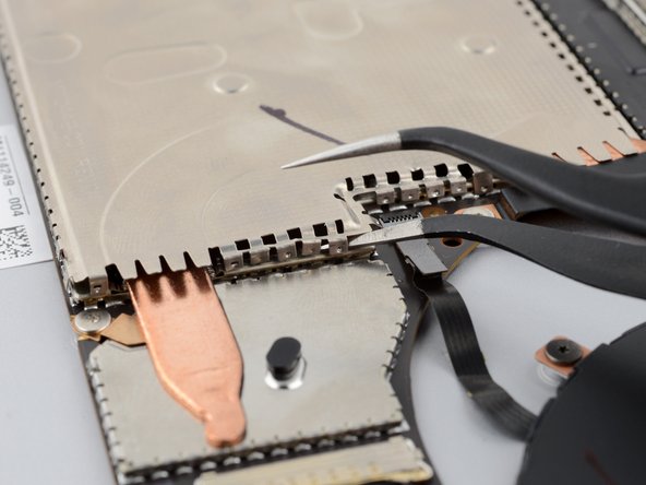
– Take the pokey end of your spudger and gently flip up that locking flap on the fan cable ZIF connector—like opening a tiny treasure chest!
– Grab the fan cable pull-tab with your trusty tweezers and smoothly slide the cable straight out of the connector. Easy breezy!
Step 18

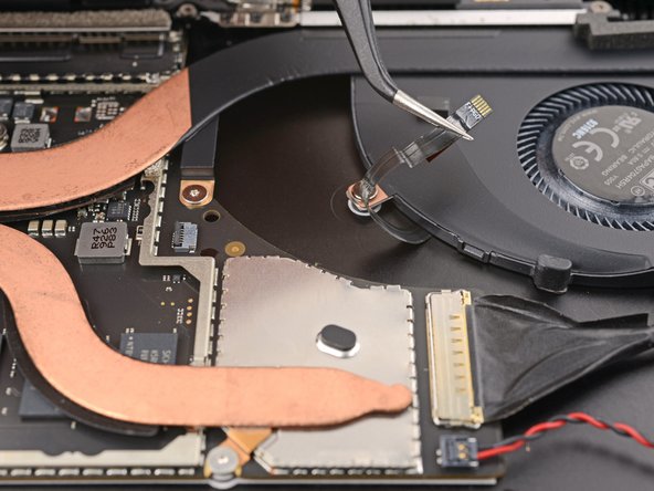
The fan cable is held snugly in place by some trusty adhesive, keeping everything nice and secure.
– Grab some tweezers or your fingers and gently unstick the fan cable from the frame—it’s like peeling off a sticker, but way cooler!
Tools Used
Step 19

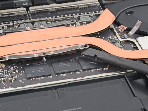
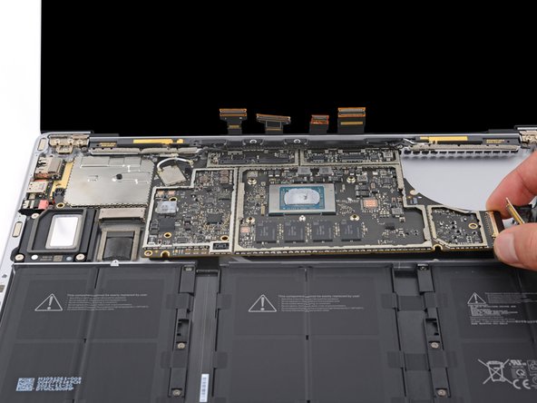
– Grab your T3 Torx driver and tackle those ten screws holding the heatsink in place:
– Two 2.5 mm screws
– Three 2.0 mm screws
– One 3.0 mm screw
– Two 4.1 mm screws
– Two 3.4 mm screws
Step 20

– As you put everything back together:
– Make sure to line up that heatsink with the centering peg on the motherboard. It’s a perfect match!
– Now, when it’s time to tighten those four CPU tension screws, do it in an ‘X’ pattern. Think top left, bottom right, top right, and then bottom left. You’ve got this!
Step 21

You might need to use a bit of muscle for this step. Just make sure those heat pipes stay straight and cool as a cucumber!
Thermal paste is the magical goo that helps the heatsink stick to the CPU like best buddies. It’s essential for keeping everything nice and cool!
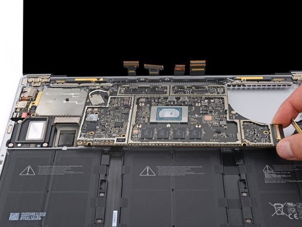
– Slip your spudger under the left heat pipe.
– Lift to free the left part of the heatsink.
– Do the same for the right heat pipe and CPU screw mounts until the heatsink is totally separated from the motherboard.
Tools Used

Step 22


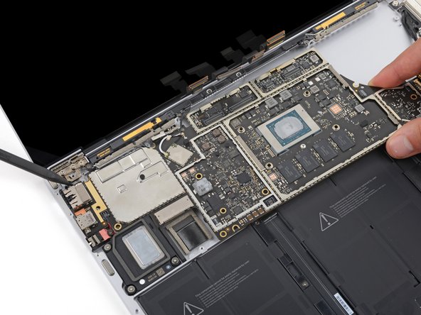
– Gently use your finger to lift the right edge of the heatsink, sliding it over the alignment peg near the right side of the fan.
– Carefully pull the right edge of the heatsink away from the screen, releasing it from its snug spot in the frame.
Step 23


Take it easy on that heatsink! It’s a bit delicate, and those heat pipes can bend if you’re too rough. If it’s giving you a hard time, just give it a gentle wiggle to help it along.
– Time to take off that heatsink! Gently remove it and set it aside—it’s been doing a lot of hard work keeping things cool, but now it’s your turn to shine!
Step 24


– Before you dive into reinstalling that heatsink, take a moment to give the heatsink and CPU a good scrub and refresh with some new thermal paste. Trust us, your device will thank you for it!
Tools Used
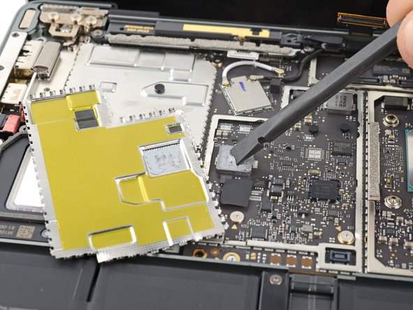
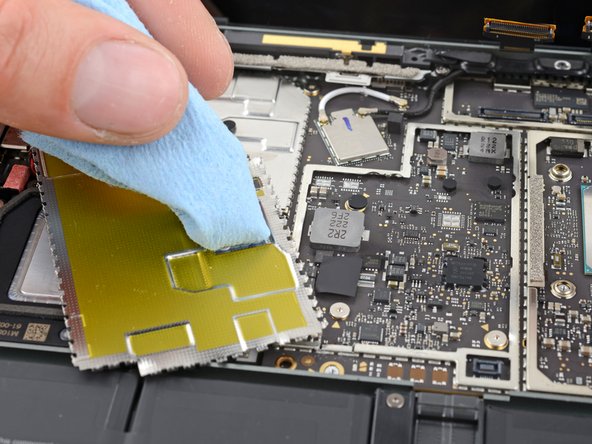
Step 25


Be gentle with the shield! It’s important to keep it in shape since you’ll be putting it back on later during reassembly.
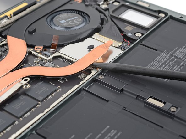
– Slide one arm of your trusty tweezers under the corner of the left display cable shield.
– Gently lift it up to pop those clips holding the shield in place.
– Keep going around the edges of the shield until it’s free and clear!
Tools Used
Step 26

– Gently slide the left display cable shield away from the screen to release it from its snug little home.
– Now, go ahead and take off the shield!
Step 27

– Follow the last two steps again to pop off the right display cable shield—you’re almost there!
Step 28


To get to some of the motherboard screws, you’ll need to pop off two metal shields. Just don’t get too wild with it—you’ll need to put them back on during reassembly.
Try not to deform the shield too much. You’ll need to reinstall it during reassembly.
– Slide one arm of your tweezers under the corner of the left touchpad shield—easy does it!
– Give it a gentle wiggle and lift to pop those clips holding the shield in place.
– Keep cruising around the edges, repeating the process until the shield is free and ready to be removed.
Tools Used
Step 29

– Take off the left motherboard shield with care.
Step 30

You might find some thermal paste hanging out between the motherboard and its left shield.
– Before putting the left motherboard shield back in place, take a moment to clean off the old thermal paste and apply a fresh layer. It’ll keep things cool and running smoothly—your device deserves the TLC!
Tools Used
Step 31

– Gently slide one arm of your tweezers under the corner of the right motherboard shield, and work your way around its edge to pop those clips loose.
– Carefully lift off the right motherboard shield.
Tools Used
Step 32

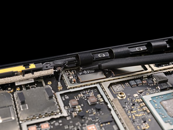
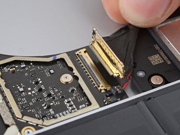
– When putting everything back together, grab the flat end of your spudger and carefully slide the display cables back into their home in the lower case after reconnecting the press connectors. Take it slow and steady!
Tools Used
Step 33

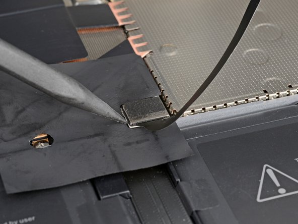
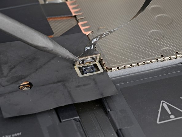
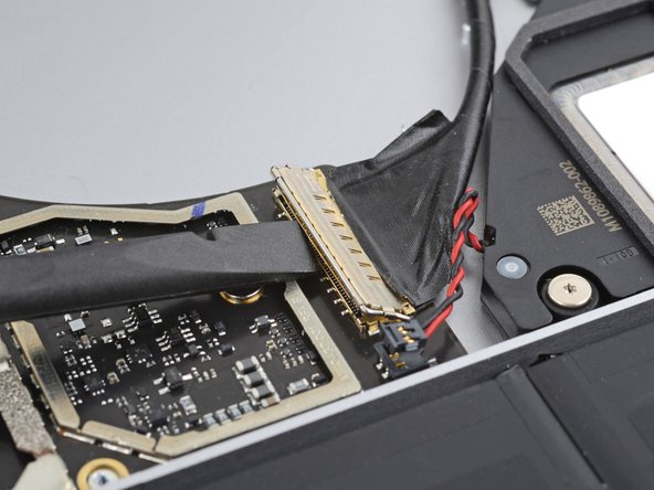
To get that connector back in place, carefully line it up and gently press down on one side until you hear it click. Then, repeat the process on the other side. Just remember, no pressing down in the middle, or you might end up with some bent pins and a bigger problem on your hands. Take your time, and you’ll be golden!
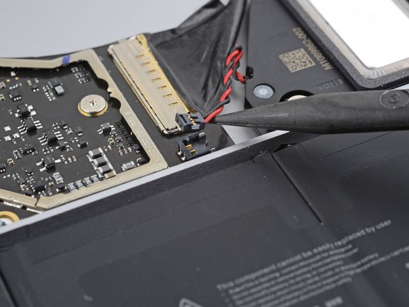
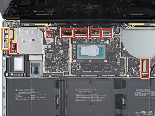
– Time to get those cables disconnected! Use the flat end of a spudger to carefully pry up and release all four display cable press connectors. Take your time and work your way through each one – you got this!
Tools Used
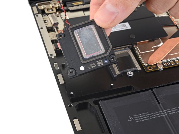
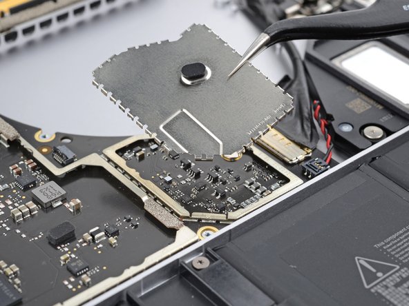
Step 34

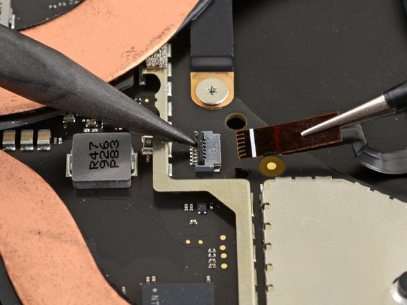
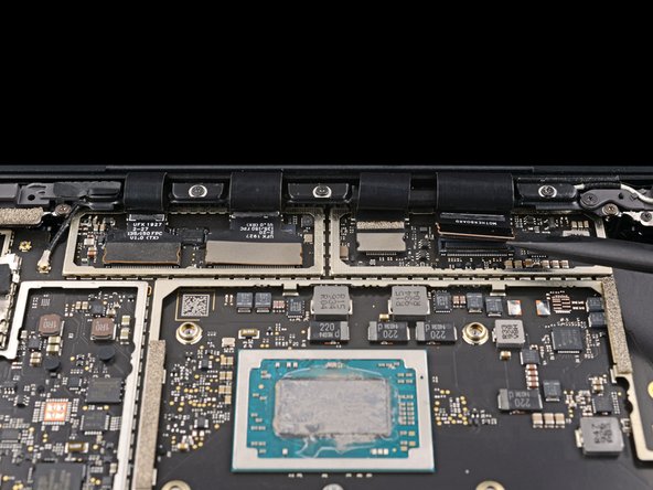
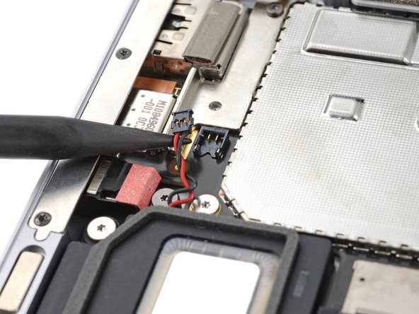
– Gently use the sharp end of a spudger to carefully lift and unplug the right speaker wire from its connector on the motherboard. You’ve got this!
Tools Used
Step 35

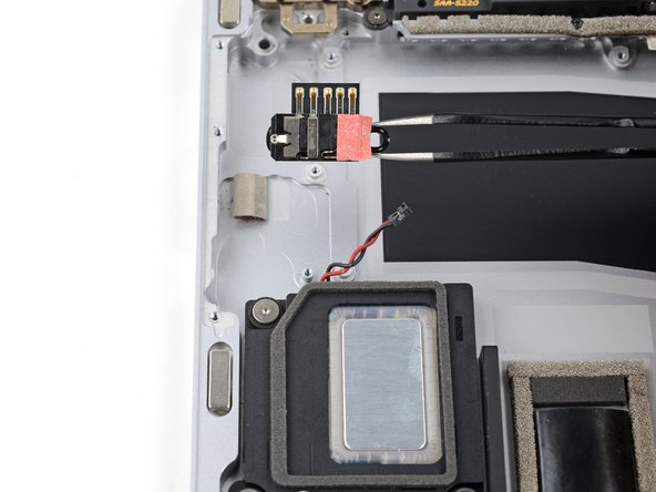
– Take your trusty spudger and gently pry open the locking arm on the Surface Connect port connector. You’ve got this!
– Now, give the Surface Connect port cable a firm grip and confidently pull it straight out of its socket. Easy peasy!
Tools Used
Step 36

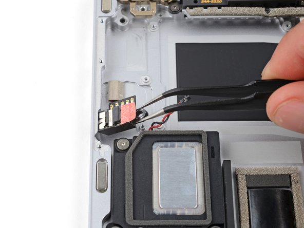
– Now it’s time to disconnect the left speaker wire – use the pointed end of a spudger to gently lift it away from its connector, located near the left ports. You got this!
Tools Used
Step 37
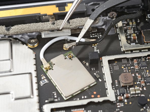

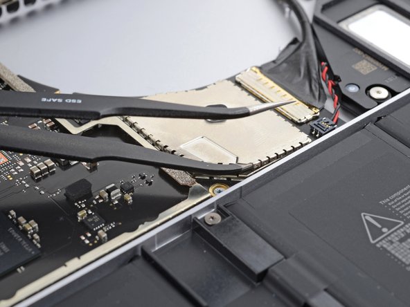
– Get one arm of your tweezers under the black antenna connector, right up close to the head.
– Lift it straight up to pop off the cable.
– To reconnect the antenna, just line up the head of the connector over its socket and press down with the flat end of a spudger. You’ll hear it snap back into place.
Step 38

– Grab your trusty T3 Torx driver and let’s tackle those two 3 mm screws holding the motherboard bracket in place. You’ve got this!
Step 39
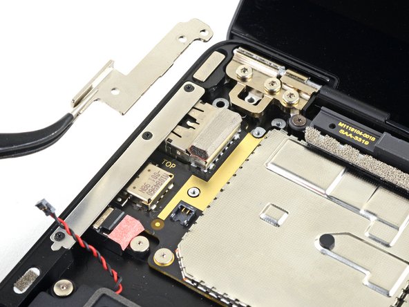

– Take off the motherboard bracket with care.
Step 40
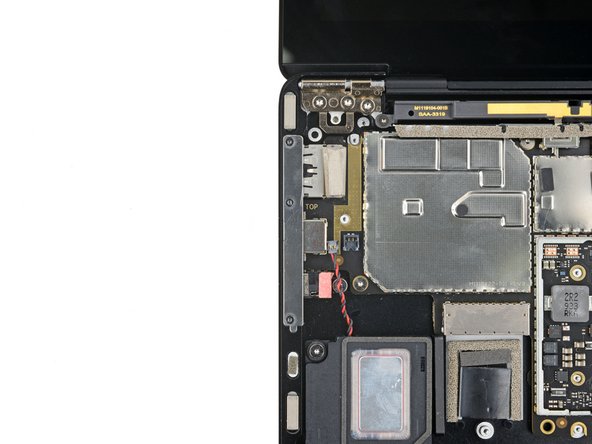

– Grab your T3 Torx driver and unscrew the three 2.1mm screws holding the left port cover in place.
Step 41
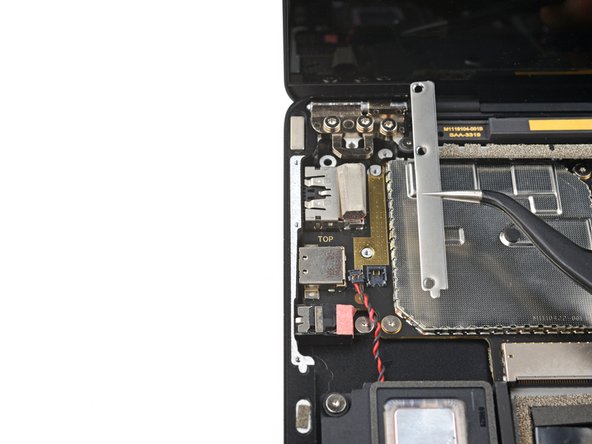

– Pop off the left port cover like a pro and get ready to move on to the next step—you’re doing great!
Step 42

If your screws are sporting rubber covers, go ahead and peel those off like a pro!
– Grab your trusty T3 Torx driver and go ahead and unscrew those six 2 mm screws that are holding the motherboard in place. You’re doing great!
Step 43

The left side of the motherboard is snugly tucked in by the port openings, the speaker, and the frame. It’s like they’re all best friends holding each other tight!
– Gently lift the right edge of the motherboard just a tad above the battery.
– Keep the motherboard steady while you tackle the next step to release the left edge.
Step 44

There’s a little tab on the upper left of the motherboard that snugly fits against some bumps in the frame, keeping the left edge nice and secure.
If the motherboard isn’t budging over the left speaker, that tab might still be holding on tight. Just adjust the angle of your spudger and give it another go!
– Slide the tip of your trusty spudger into the upper left corner of the motherboard where the tab is hanging out. Gently nudge it between the frame and that screen hinge—easy does it!
– Now, give that tab a little pop with your spudger while you lift the right edge of the motherboard toward the front of the laptop. You’re doing great—keep it up!
Tools Used
Step 45

Don’t let those two screwpost braces hiding under the motherboard vanish during the removal—keep an eye on them!
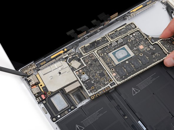
– Pop out the motherboard like a pro.
– When you’re putting everything back together:
– Watch out! Don’t let any of those eight cables get squished underneath—give them some breathing room.
– Line up the left ports snugly in their spots before sliding the motherboard back in place. Smooth moves!
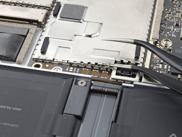
Step 46

– Grab your trusty T3 Torx driver and take out that 2.4 mm screw holding the headphone jack in place. Easy does it—you’ve got this!
Step 47

– Before you install the new part, take a moment to compare it to the original—sometimes you’ll need to move over any remaining components or peel off adhesive backings.
– To put everything back together, just reverse these steps.
– Got old electronics? Be sure to recycle them responsibly at an R2 or e-Stewards certified recycler.
– If things didn’t go according to plan, don’t stress! A little troubleshooting might do the trick, or check out our Answers community for tips and support.
–
Success!