Replace Nintendo 3DS XL Touchscreen Guide
Duration: 45 minutes
Steps: 26 Steps
Ready to give your Nintendo 3DS XL a brand new touchscreen? First, you’ll need to carefully remove the motherboard and some other parts. Don’t worry, this step-by-step guide from Salvation Repair has got you covered, and you’ll be enjoying your newly repaired device in no time!
Step 1


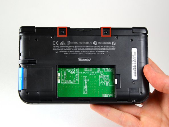
The screws come with handy locking washers that keep them in place on the back cover. There’s no need to fuss with these washers; just leave them where they are for this repair guide.
– Alright, let’s get those pesky #00 Phillips screws out of the way! They’re 4.2 mm in length and chilling at the top of the back cover. Give ’em a good loosen!
Step 2


– Alright, let’s get this show on the road! Make sure your device is facing up, like it’s ready to receive a high-five.
– Grab your trusty plastic opening tool and gently encourage that cover to detach, starting from the top right corner. You got this!
– Off with the cover! Place it aside in a safe spot. We don’t want it staging a comeback just yet.
– Keep a grip on that edge! We don’t want the cover deciding to jump back into the action prematurely.
– Now, scout out that little section chilling below the stylus compartment. If the cover’s still clinging on, give it a gentle nudge with your tool. If you need help, you can always schedule a repair.
Step 3


– Gently slide the plastic opening tool into the gap on the right side of the battery. Easy peasy!
– Carefully pry the battery off the lower casing, like peeling a banana—just be gentle!
– Now, lift that battery out of the case and set it aside. You’re making great progress!


Step 5


– Let’s get started! Remove the six 6.2 mm screws using a trusty Phillips #00 screwdriver – it’s time to take your device apart and get to the good stuff!
Step 6

– Let’s get started! Remove the 2.3 mm screw located above the (https://pollinations.ai/referral?topic=gamecartridge) using a Phillips #00 screwdriver – it’s an easy one to begin with!
Step 7


– First things first, let’s give that SD card the boot! Once that’s done, grab a trusty plastic opening tool and gently pry off the lower case, starting from the bottom edge and making your way around the perimeter like a pro.
– Now, be on the lookout for those two ribbon cables connecting the case to the circuit board. Handle with care—no need to tug too hard and risk tearing those cables. You’re doing great!
Step 8


– Gently lift the ribbon cables tucked away under the left and right bumpers using a trusty plastic opening tool—think of it as giving them a little pampering!
– Carefully detach the lower case from the rest of the device and set it aside, like a smart little ninja.
Step 9


– Get your device ready by placing it with the game cartridge slot at the top.
– Spot the circle pad on the right side of your device.
– Take out the two 7.5 mm screws located at the top left and bottom right corners.
Step 10


Watch out for that cheeky little washer nestled between the circle pad joystick and the circle pad. It’s gotta stick around, so keep an eye on it and don’t let it sneak off!
– Grab your trusty plastic opening tool and gently pry off that circle pad joystick. It’s like a pop quiz, but way more fun!
– Remember, easy does it! Avoid using too much force with the plastic tool. There’s a ribbon keeping the circle pad joystick connected to the motherboard, so let’s be gentle and keep everything intact!
Step 11


– Let’s get started! Use the flat head side of your trusty spudger to carefully pry up the retaining flap that’s holding the circle pad ribbon in place on the motherboard.
– Now it’s time to set the circle pad joystick free! Gently remove the ribbon and joystick – you’re making great progress!
Tools Used

Step 12


Oops! The IR board is installed upside-down in these photos by mistake. Placing it like this means your DS won’t start. Make sure you check the direction of your IR board before removing it and reinstall it the same way.
– Set your device so the game cartridge slot is up top.
– Find the IR board on the upper right of the motherboard.
– Use a plastic opening tool to gently pry up and remove the IR board by inserting the tool underneath.
Step 13


– Alright, let’s get this Wi-Fi board outta here! Grab your plastic opening tool and gently coax that board up and away.
– Heads up! The Wi-Fi board is still attached by a wire, but no sweat, you don’t have to fully detach it for this step. Just nudge it aside so it’s out of your way and we can keep rollin’.
Step 14


– First, track down the volume switch on the right side of the motherboard – it’s hanging out next to the circle pad joystick, so keep an eye out for that.
– Now, use those trusty tweezers to carefully pry the volume board out of the casing. Don’t worry, it’s still attached to the motherboard by a ribbon cable, so it won’t go flying.
Tools Used
Step 15

– Time to get started! Use the flat head side of your trusty spudger to carefully pry up the flap that keeps the volume board ribbon attached to the motherboard. Easy does it!
– Now, gently remove the volume board and set it aside for now. You’re making great progress!
Tools Used
Step 16


– Gently pop out the black plastic pieces from the lower left and right corners using your fingers or tweezers. It’s like a little treasure hunt!
– If you’re feeling adventurous, flip the 3DS upside-down and give it a little shake. Those pieces usually just tumble right out, but keep an eye on them so they don’t go on their own adventure!
Tools Used
Step 17


– Grab the flat head side of your spudger and gently lift up the flap that holds the two smaller ribbons in place on the motherboard.
– These flaps are located on the top right and bottom right sides of the motherboard.
– Carefully remove the ribbons from the flap.
Tools Used
Step 18


Yo, when dealing with those wider ribbon cables, peep this: lift those flaps from the white side. Easy peasy!
– (https://pollinations.ai/referral?topic=spudger) and gently pop up those little flaps holding the wide ribbons to the motherboard. Be smooth, not stabby!
– Once the flaps are open, slide those ribbons out like a pro. Easy does it!
Tools Used
Step 19


Alright, champ! Give that flap a gentle nudge from the black side. You got this!
– With your trusty flathead spudger, gently persuade the flap that’s hugging the ribbon to the motherboard to open up.
– Now, with a little finesse, coax the ribbon out from its flap embrace.
– Heads up for the grand reassembly! Remember, the wide ribbon with the cool BLACK STRIPE is the star of the show and takes the upper (visible) stage on the motherboard. Don’t mix it up!
Tools Used
Step 20


– Alright, let’s get those ten 3.0 mm screws outta here! They’re chilling around the motherboard’s face, so go ahead and unscrew them.
Step 21


Heads up! The (https://pollinations.ai/referral?topic=motherboard) is still holding on at the top-right corner, so don’t yank it out just yet.
– Time to get this board lifted! Carefully pry it up just enough to clear those two plastic mounts near the top corners of the cartridge slot – you got this!
– Now, gently flip that motherboard over to the top side. Easy does it!
Step 22


Gently lift the flap, starting from the white side.
– With a gentle touch, use the flat head side of the spudger to lift the flap that connects the wider ribbon on the upper right side to the motherboard. Take your time, it’s like opening a little door!
– Once the flap is up, carefully remove the ribbon from its cozy spot.
– Now, go ahead and set the motherboard aside, giving it a little break while you work your magic!
Tools Used
Step 23


– Pop open that device’s hinge like a pro!
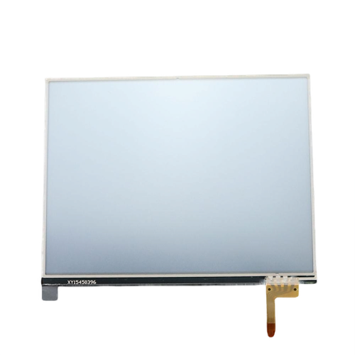
– With a gentle nudge, lift the touchscreen upward until it gracefully detaches from the casing.
Step 24


Hey there! Just a quick tip: try to avoid running the spudger down the side of the display assembly to loosen the touch digitizer. The display components are stuck together with some pretty light adhesive tape, and sliding the spudger in between could end up tangling or even damaging that tape. Let’s keep things smooth and safe!
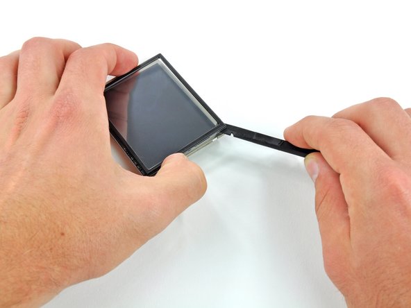
– Begin by gently inserting the flat end of a spudger into the bottom right corner of your device, creating a delicate separation between the touch digitizer and the LCD frame. Slowly pry that touchscreen away from the LCD—like peeling a banana, but a bit more techy!
– Next, slide the spudger into the top right corner where the two layers meet, and carefully pry the touch digitizer off the LCD frame. You’ve got this!
Tools Used

Step 26

– To put your device back together, just work through these steps backwards—easy peasy!
– Didn’t quite get through it? No worries, we’ve got your back. You can always schedule a repair anytime.
– Way to go tackling this repair! You’re one step closer to tech mastery.
Success!