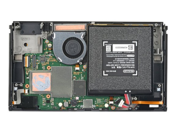
Replace Nintendo Switch OLED Fan: DIY Guide
Duration: 45 minutes
Steps: 34 Steps
For your safety, make sure the battery is below 25% before diving into disassembling your Switch. Let’s keep it safe and sound!
Ready to give your Nintendo Switch OLED a new lease on life by replacing the fan? Let’s do it! Just make sure to discharge the battery below 25% before diving in—it’s all about keeping things safe and reducing the risk of fire. Got a swollen battery? Take those extra precautions. The Switch OLED uses JIS screws, but no worries if you’ve only got a Phillips screwdriver on hand. Just be super careful not to strip those screws. Note: When you remove the shield plate, you’ll need to replace the thermal compound between the plate and the heatsink. K5 Pro viscous thermal paste is your best friend for bridging large gaps, while regular replacement thermal paste will do the trick for the heatsink itself.
Step 1


Before diving into this repair, make sure your device is totally powered off.
– Hold down that small, round button on the back of the Joy Con controller like a boss.
– While you keep that button pressed, slide the controller upward in one smooth move.
Step 2


Now, just rinse and repeat this process for the other Joy Con. You’ve got this!
– Keep sliding that Joy Con upward until it pops off the console like a champ!
Step 3


Don’t let these stubborn screws win! Keep steady, press down firmly, take your time, and if they still won’t budge, try switching up your JIS or Phillips driver—sometimes you just need the right dance partner.
– Let’s get started! Use a Phillips driver or a JIS driver to carefully remove the 2mm-long screw that’s holding the top of the rear case in place. It’s time to set that case free from the frame!
Step 4


– Grab your trusty Phillips screwdriver and unscrew the two 2 mm-long screws holding the bottom of the rear case snugly to the frame.
Step 5


To keep those stubborn screws from getting stripped, apply some solid downward pressure, take your time, and if they’re being tricky, switch to another JIS 000 or PH 000 driver. You’ve got this!
– Grab your trusty Phillips screwdriver and loosen up that 3.8 mm screw holding the right Joy-Con sensor rail to the rear case. You’re doing great—keep it up!
Step 6


– Grab your trusty Phillips screwdriver and unscrew that 3.8 mm bad boy holding the left Joy-Con sensor rail to the rear case. You’re doing awesome—keep it up!
Step 7


If your device has a microSD card chilling in its slot, take a moment to pop it out now before moving on to the next step. You’ve got this!
– Gently pop up the kickstand on the back of the device using your finger—it’s like giving your device a little stretch after a long day.
Step 8


– Let’s get started! Use a Y00 screwdriver to carefully remove the two 4.3mm screws that are holding the rear case in place. This is the first step in giving your device a brand new look and feel!
Step 9


If you’re finding it tricky to pop off the case, just grab an opening pick and gently pry up those plastic clips.
– Gently lift the rear case from the top of your device and remove it. Take your time and be careful, the device will thank you.
Step 10


– Grab the flat end of your trusty spudger and gently peel back a corner of the tape from the shield plate—like lifting the corner of a sticker. Easy does it!
Tools Used

Step 11


– Grab those tweezers or use your fingers to gently peel back and remove the tape. You’ve got this!
– Keep that tape safe in a clean spot for when you’re ready to reattach it later. Good job!
Tools Used

Step 12


– Grab your tweezers or fingers and gently pull up to disconnect the primary Wi-Fi antenna’s coaxial cable.
– During reassembly, these connectors can be a bit tricky. Take them one at a time, hold each connector in place over its socket and press down with the flat end of a spudger. You’ll hear a satisfying snap when it’s in place.
Step 13


– Grab some tweezers, or use your fingers if you’re feeling confident, and carefully reroute the primary antenna’s coaxial cable out of its cozy little slots in the shield plate.
Tools Used
Step 14


– Grab your Phillips driver and remove the two 4.4 mm screws holding the primary Wi-Fi antenna in place on the shield plate. You got this!
Step 15


– Slide an opening pick between the main Wi-Fi antenna and the shield plate—like slicing through butter, but cooler.
– Gently pry upward with the pick to lift the primary Wi-Fi antenna away from the shield plate. You got this!
Step 16


– Gently remove that main Wi-Fi antenna—it’s time to set it free!
Step 17


– Grab your trusty tweezers or just use your fingers to gently lift and disconnect that pesky coaxial cable from the secondary Wi-Fi antenna. You’ve got this!
Tools Used
Step 18


– Time to get that Wi-Fi up and running! Use the point of a spudger to carefully reroute the secondary Wi-Fi antenna’s coaxial cable from its slot in the frame. Nice and gentle does the trick!
Tools Used
Step 19


– Grab your trusty Phillips driver and unscrew the 4.4 mm screw holding the secondary Wi-Fi antenna to the shield plate. Easy peasy!
Step 20


Hold up! Don’t yank out the antenna just yet—its coaxial cable is still threaded through the frame.
– Slide an opening pick into the gap between the secondary Wi-Fi antenna and the shield plate.
– Gently lift the pick to pop the secondary Wi-Fi antenna free from the shield plate.
Step 21

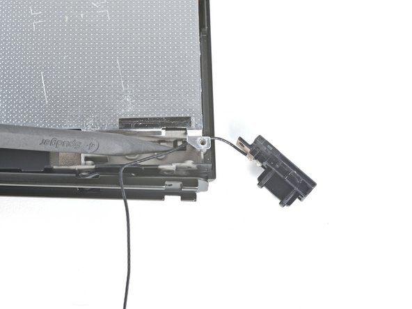

– Grab your trusty spudger and gently guide the secondary Wi-Fi antenna’s coaxial cable out of its snug little home in the frame.
– Now, it’s time to say goodbye to the secondary Wi-Fi antenna. Go ahead and remove it with care!
Tools Used
Step 22


– Let’s get started! Use a Phillips driver to carefully remove the six 4.4 mm screws that hold the shield plate in place on the frame. Take your time and make sure they’re all out before moving on to the next step.
Step 23


You might notice a little resistance here—don’t sweat it! That’s just the shield plate holding onto the heat sink with some thermal paste. Totally normal.
– Gently use your fingers to lift the top of the shield plate away from the frame.
– Carefully remove the shield plate.
– You’ll notice a thick pink thermal compound bridging the gap between the shield plate and the copper heat sink underneath. Whenever you remove the shield plate, be sure to check out our thermal paste guide to clean off the old thermal compound and replace it with a fresh one like K5 Pro during reassembly. If you need help, you can always schedule a repair.
Step 24


– Gently use the tip of a spudger to lift and disconnect the battery. You’ve got this!
Tools Used
Step 25


– Grab some tweezers or just use your fingers to gently peel away the tape that’s hiding the screw for the daughterboard. You’ve got this!
Tools Used
Step 26


– Grab your trusty Phillips screwdriver and unscrew the 4 mm screw that’s keeping the daughterboard snug in the frame. Easy peasy!
Step 27


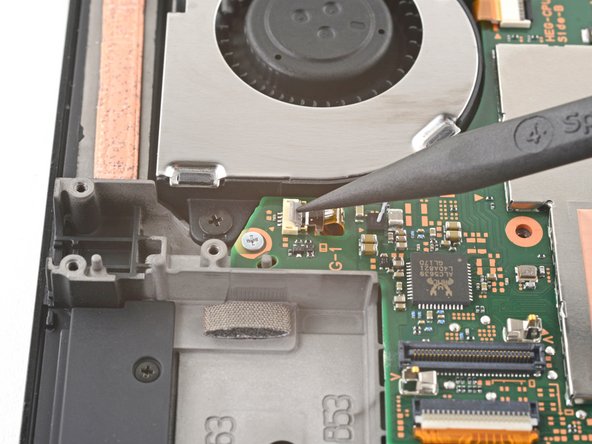
The underside of the daughterboard connects to the motherboard with a nifty press connector.
– Slide a spudger between the daughterboard and the motherboard like you’re parting two besties after a disagreement.
– Gently pry up with the spudger to pop that press connector free and let the daughterboard step out from the frame.
– Now, remove the daughterboard like a pro—easy peasy!
– When it’s time to reattach those press connectors, line things up carefully. Press down on one side until you hear that satisfying click, then do the same on the other side. Avoid pressing smack in the middle; misaligning can bend the pins and cause some serious damage you don’t want. Take it slow and steady!
Tools Used
Step 28


– Grab your trusty Phillips screwdriver and take out the trio of 3 mm screws holding the heat sink snugly on the motherboard. You’ve got this!
Step 29


You might notice a little pushback here, and that’s totally cool! It’s just the heat sink giving a gentle hug to the CPU thanks to some thermal paste. No worries, you’re doing great!
– Wedge your spudger between the heat sink’s bracket and the motherboard—you’re like a tech ninja!
– Give it a gentle pry with the spudger to lift the heat sink off the motherboard. Slow and steady wins the race!
Tools Used
Step 30


– Gently slide a spudger into the gap between the fan and the heat sink.
– Carefully pry with the spudger to lift the heat sink off the adhesive that’s holding it down.
– Now, remove the heat sink from the area.
– Take some high-concentration (90% or higher) isopropyl alcohol and a microfiber cloth to clean off the old thermal paste from both the heat sink and CPU. Once it’s all clean, don’t forget to apply fresh thermal paste to the CPU before putting everything back together.
Tools Used
Step 31

– Gently use the tip of a spudger, an opening tool, or even your trusty fingernail to lift up that little hinged locking flap on the fan cable’s ZIF connector. You’ve got this!
Tools Used
Step 32


– Grab a trusty pair of tweezers and gently tug the fan cable straight out from its cozy connector on the motherboard. You’ve got this!
Tools Used
Step 33

– Grab that trusty Phillips driver and carefully unscrew the three 3mm screws holding the fan to the frame.
Step 34


– To put your device back together, just retrace your steps in reverse—easy peasy.
– Things not going as smoothly as expected? No worries, try some basic troubleshooting, or if you’re stuck, feel free to schedule a repair.
– Take a good look at your new part and compare it to the original one. You might need to swap some components over or peel off any adhesive backings before installing.
– And you’re done!
Tools Used
Success!