Replace Samsung Galaxy Note20 Rear Camera: Step-by-Step Guide
Duration: 45 minutes
Steps: 32 Steps
Hey there, tech wizard! Before you get started, let’s make sure your device is chill. Just give it a little time to cool down – let the battery power drop below 25%. It’s all about keeping things safe and smooth for the repair. If you need help, you can always schedule a repair.
Ready to give your Samsung Galaxy Note20’s camera a new lease on life? This guide will walk you through replacing the rear camera module. Just a heads-up: Always make sure your phone’s battery is below 25% before you start taking things apart. This helps keep things safe and prevents any potential battery-related mishaps. If your battery is looking a little puffy, just be extra careful. And remember, if you need help, you can always schedule a repair.
Step 1


No need to panic if you accidentally poked the SIM eject tool into the microphone hole! Chances are, your microphone is just fine.
– Grab your trusty SIM eject tool, a bit, or even a straightened paperclip, and slide it into the SIM card tray hole located on the top edge of your phone.
– Give that SIM eject tool a little push into the SIM card tray hole to pop out the SIM card tray with style.
– Carefully remove the SIM card tray, and you’re all set!
Step 2

Before diving into the disassembly adventure, make sure to power down your phone completely. Safety first, right?
Feel free to use a hair dryer, heat gun, or hot plate to warm things up a bit, but keep an eye on the heat! The screen, internal battery, and plastic rear cover can be a bit sensitive to high temperatures.
– Let’s get started by heating up an iOpener and applying it to the left side of the rear cover for about a minute. If you need help along the way, you can always schedule a repair
Tools Used

Step 3


Hey, just a quick heads up, don’t go overboard with the opening pick. You wouldn’t want to go too deep (more than 5 mm) and accidentally hurt your phone’s inner workings, right? Take it slow and steady, you got this! If you need help, you can always schedule a repair.
Depending on how old your phone is, this might be a bit tricky. Don’t worry, if you’re having trouble, just give that edge some extra heat and try again. You got this! If you need help, you can always schedule a repair.
– Let’s get this party started! Grab your suction cup and stick it to the heated edge of the rear cover, right on the edge if you can.
– Now, pull up on that suction cup with some serious strength and steady hand – we’re going to create a little gap between the rear cover and the frame.
– Time to get your tool in there. Slide that opening pick into the gap and get ready for the next step. If you need help, you can always schedule a repair.
Step 4


Hey, be careful! When you’re slicing through that sticky stuff around the phone, don’t push your pick in more than 5mm, or you might accidentally bump into some important parts inside. Stay cool and keep it chill! 😉
– Let’s loosen that adhesive! Slide the opening pick along the left edge toward the bottom left corner. You’re cutting through the adhesive, like a hot knife through butter!
– Now, keep that pick in the bottom left corner. We don’t want that adhesive sealing itself back up. It’s a slippery little bugger, that adhesive!
Step 5


If the rear cover is still clinging on after you’ve sliced through all four sides, give that adhesive another go with your opening pick—let’s show it who’s boss!
Feel free to slide each new opening pick into the cozy gaps made by the picks you’ve already placed in the corners. Teamwork makes the dream work!
– Keep the good times rolling by heating and slicing through the adhesive on the last three sides of the rear cover. You’re almost there!
– As you work your magic, pop an opening pick in each corner to keep that adhesive from getting cozy again.
Step 6


– Time to get started – carefully lift the rear cover straight up to remove it. If you need help, you can always schedule a repair
Step 7

If these screws are still hanging on for dear life, they might be a bit tricky to budge since they’ve got some threadlocker keeping them snug. No worries, though!
As you tackle this repair, keep an eye on each screw and remember where it belongs. It’s like a little puzzle, and you’ll want to put it back together just right!
– Alright, grab your trusty Phillips screwdriver! We’re gonna remove those six 4.0 mm screws holding the motherboard shield in place. It’s like giving your device a little massage, but with screws instead of fingers.
Step 8


Hey there, Just a heads up! The motherboard shield has some pretty sharp edges. Be gentle when handling it, ok?
– Grab a trusty pair of tweezers and gently lift up that motherboard shield, then flip it back like a pro!
Tools Used

Step 9


Be careful to gently pry only at the edge of the connector; we don’t want to hurt the socket or any nearby components. Let’s keep everything in tip-top shape!
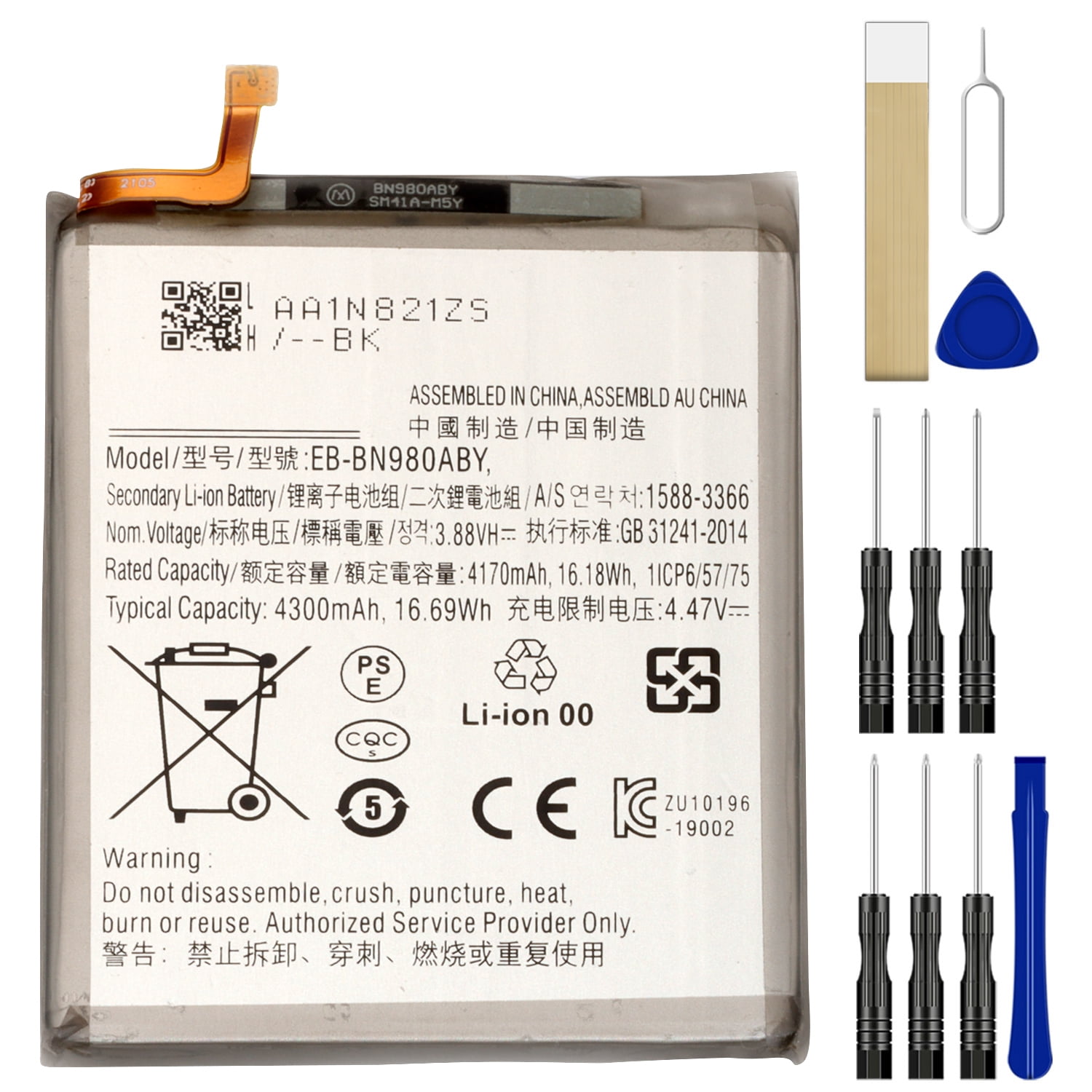
– Grab your tweezers and give that motherboard shield a gentle nudge out of the way. Then, use the pointed end of your spudger to give that battery press connector a little lift.
– Now, let’s put that connector back in place! Carefully line it up and give one side a gentle press until you hear that satisfying click. Repeat on the other side, but be careful not to press down in the middle. If it’s not lined up perfectly, those tiny pins can bend and that’s not good. If you’re feeling nervous, you can always schedule a repair.

Step 10


– While using a pair of tweezers to gently keep the motherboard shield out of the way, take the pointed end of a spudger and carefully pop up the wireless charging coil press connector. You’ve got this!
Step 11


That wireless charging coil is glued on with a little bit of sticky stuff. Don’t worry, we’ve got you covered. You’ll be able to take it off easily with the right tools.
– Get a good grip on the motherboard shield with your fingers – it’s time to get started!
– Carefully peel the wireless charging coil up and away from the device, taking your time to avoid any damage.
– Now, remove the wireless charging coil completely. If you need help, you can always schedule a repair
Step 12

– Grab your trusty Phillips screwdriver and get ready to tackle those five 4.0 mm screws holding the loudspeaker snugly to the frame. You’ve got this!
Step 13


Hey there, champ! Be careful when you’re using the tweezers around the battery. You don’t want to puncture it or bend it—it could leak some icky chemicals or cause a little meltdown. If you need help, you can always schedule a repair.
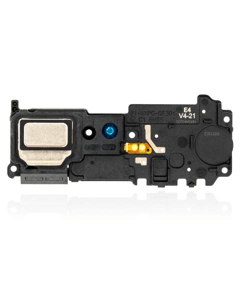
– Let’s get that loudspeaker out! Gently slide the pointed end of your spudger underneath the loudspeaker, near its top left screw hole.
– Now, give that loudspeaker a little nudge. Use the spudger to pry up and separate it from the frame.
– Almost there! Use your trusty tweezers to carefully lift and remove the loudspeaker. You’re doing great!
Step 14

– Grab your trusty Phillips screwdriver and carefully take out the five 4.0 mm screws that are holding the earpiece speaker snugly to the frame. You’ve got this!
Step 15


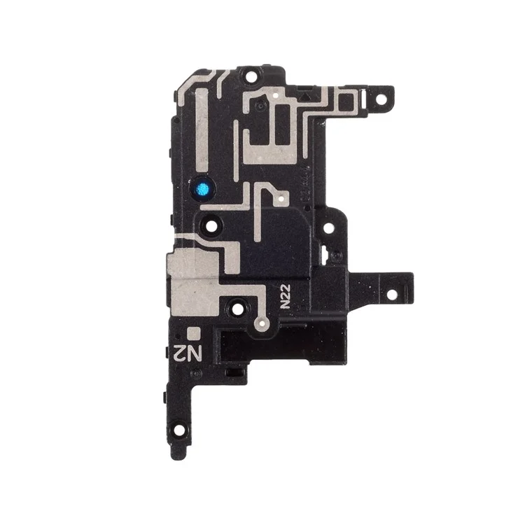
The earpiece speaker attaches snugly to the frame at the top edge.
– Let’s get that earpiece speaker out! Use the flat end of a spudger to gently pry it loose from the frame. You’ve got this! We’re almost there!
– Go ahead and pry up the earpiece speaker. It’s just waiting to come out and say hello. You’re doing great!
Tools Used
Step 16


– Time to give that earpiece speaker a little lift! Carefully remove it, and you’ll be well on your way to a successful repair. If you need help, you can always schedule a repair
Step 17


Hey, the front-facing camera is just hanging out there, attached to the motherboard with a connector. Be careful when you’re prying up the connector, because that camera might take a little flight! No worries, just be gentle and you’ll be good to go. If you need help, you can always schedule a repair.
– Gently use the pointed end of a spudger to lift the front-facing camera press connector; it’s like giving it a little nudge to say, ‘Hey there, let’s get you out!’
Tools Used


Step 19


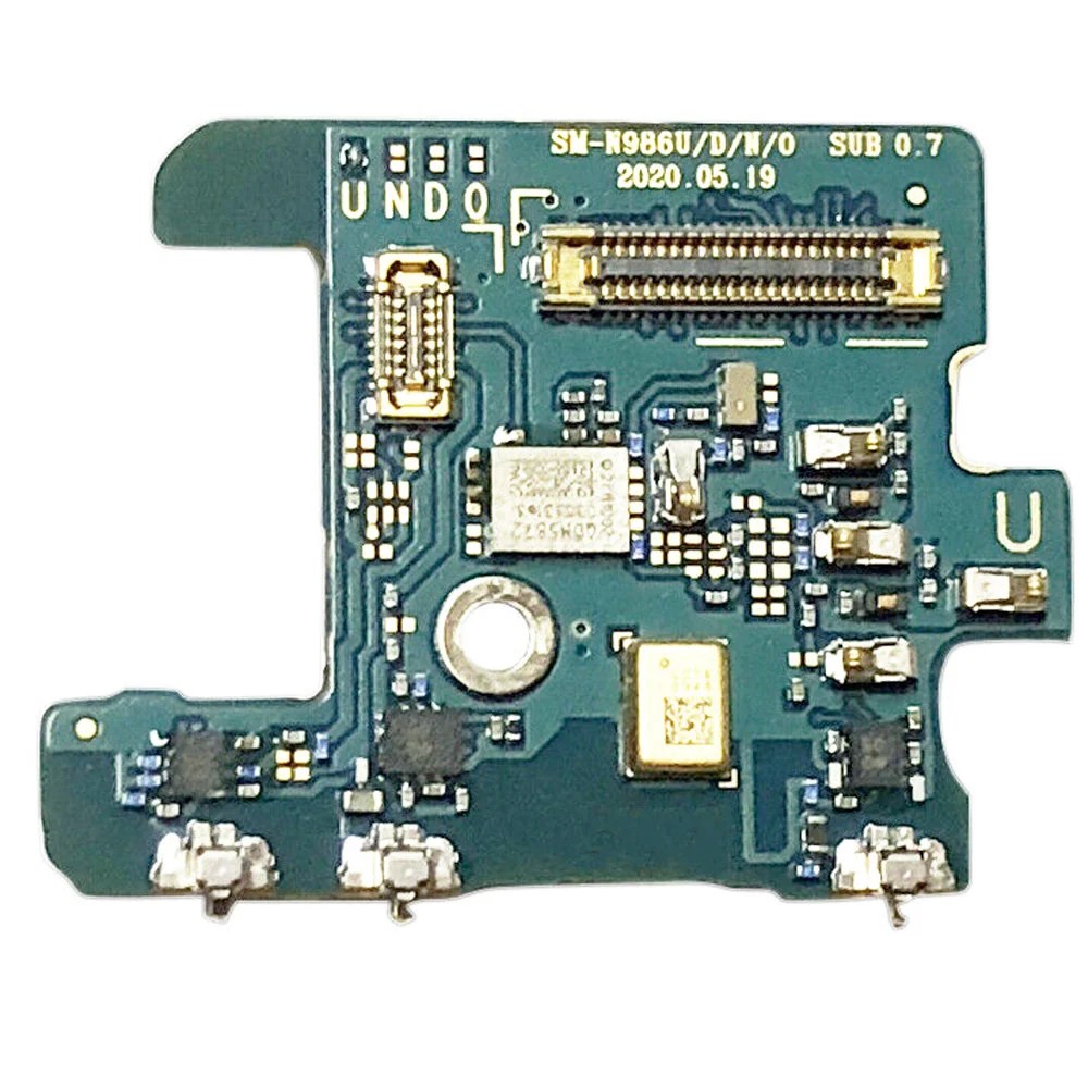
– Now it’s time to disconnect the secondary interconnect cable from the daughterboard. Use the pointed end of a spudger to gently pry it loose. If you need help, you can always schedule a repair
Tools Used


Step 21


– Grab your trusty spudger and gently use its pointed end to unplug the display cable from the motherboard. You’ve got this!
Tools Used
Step 22


– Grab your trusty spudger and gently use its pointed end to unplug the main interconnect cable from the motherboard. You’ve got this!
Tools Used
Step 23


– Alright, let’s get that secondary interconnect cable disconnected from the motherboard. Grab your spudger and use the pointed end to gently pry the cable off. No need to be rough, just a little encouragement is all it needs.
Tools Used
Step 24

– Grab your trusty spudger and gently use its pointed end to unplug the S-Pen press connector from the motherboard. You’ve got this!
Tools Used
Step 25


– Grab your trusty spudger and gently use the pointed end to pop that green press connector off the motherboard. You’ve got this!
Tools Used
Step 26


– Now, grab that spudger (you know, the pointy end) and give that touch layer press connector a little nudge. Gently disconnect it from the motherboard. We’re almost there!
Tools Used
Step 27

– Grab your trusty Phillips screwdriver and get ready to loosen the 4.0 mm screw that’s holding the motherboard snugly to the frame. Let’s get that part ready for action!
Step 28


– Alright, let’s get that motherboard out! Slide the pointed end of your trusty spudger under the bottom left corner of the motherboard. We’re gonna gently lift that bad boy out.
– Now, give that motherboard a little pry straight up to loosen it from the frame. You got this!
– Time to lift that motherboard out of the phone. Careful not to drop it! If you need help, you can always schedule a repair.
Tools Used
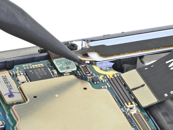
Step 29

– Flip that motherboard over like you’re showing off the back of a fancy phone! You want those camera connectors facing the sky.
– Grab your spudger, the pointed end, and give that upper camera connector a little lift-off from the motherboard. Think of it like giving it a high five.
Tools Used
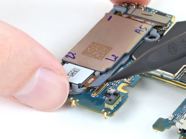
Step 30

– Time to get up close and personal with that motherboard. Use a trusty pair of tweezers to carefully lift and remove the upper camera – it’s like a little liberation for your device. If you need help, you can always schedule a repair
Tools Used
Step 31


– Grab your trusty spudger and use the pointed end to gently lift the lower cameras’ press connector off the motherboard. It’s like giving it a little high-five, but without the excitement (and the germs).
Tools Used
Step 32

– Time to give those lower cameras a little break! Carefully lift them right off the motherboard. No worries, they’ll be back in action soon.