Replace Samsung Galaxy Note9 Headphone Jack
Duration: 45 minutes
Steps: 31 Steps
Headphone jacks can be a bit moody, only working when they feel like it. But don’t worry, living with a finicky jack is not the answer! Let’s go ahead and replace the headphone jack on your Samsung Galaxy Note9 with this straightforward guide. If you need help, you can always schedule a repair.
Step 1


– Take your trusty SIM card eject tool and gently slide it into the little hole on the SIM card tray.
– Give it a gentle push to pop that SIM card tray right out!
Tools Used

Step 2

The SIM card should come out of the tray pretty easily, so don’t worry if it falls out – it’s supposed to! If you need help, you can always schedule a repair
– Pop out the SIM card tray with a swift flick.
Step 3

– Let’s get started by powering down your phone. Safety first, right? 😉
– Now, grab a hairdryer, heatgun, or a handy iOpener and gently warm up the right edge of the back of your phone for about a minute. This will help loosen up the adhesive holding the back panel in place. Don’t worry, we’re just making things a bit easier for ourselves! 😊
Tools Used

Step 4


Don’t be a brute! If the adhesive is stubborn, just give it a little more heat. No need to get rough, we don’t want any cracks! If you’re having trouble, you can always schedule a repair.
Hey there! If that phone screen’s looking worse for wear with a cracked selfie, tape it up with some slick packing tape so your sucker can stick even better. You’ve got this! Why not check out our handy-dandy guide on how to schedule a repair while you’re at it?
– Grab your trusty suction handle and stick it to the back cover.
– Gently lift with the handle, making a tiny space between the cover and the phone’s frame.
– Now, slide an opening pick into that little gap you made. You’re doing great!
Tools Used

Step 5

If the adhesive is being stubborn, give it a little more heat—no need to get rough!
– Heads up! There’s a bit more sticky stuff along the top edge and around the camera, so be careful not to lose your cool.
– Now, we’re getting down to the nitty-gritty. Carefully cut around the left edge near the fingerprint sensor – it’s a delicate area! You wouldn’t want to mess with the ribbon cable inside, right? Just take it slow and easy.
Step 6


Keep that pick under control! Don’t push it more than halfway into the phone when you’re working around the fingerprint sensor or cameras, or you might end up giving those internal components an unexpected adventure.
– Begin at the center and glide that opening pick up and down the right side to slice through the adhesive like a pro!
Step 7


Hey, be careful around the corners! The glass is a little delicate. No worries, just keep applying heat if the adhesive gets stuck. If you need help, you can always schedule a repair.
– Pop an opening pick into the upper-right corner to get things started.
– Grab another opening pick and carefully slice through the adhesive at the bottom-right corner.
– Keep that opening pick right where it is in the phone for now.
Step 8

– Let’s get this adhesive nice and loose! Grab your heat gun, hair dryer, or a heated iOpener and apply it to the left side of the rear panel for at least three minutes. This will help soften the adhesive underneath, making it easier to get things moving.
Tools Used
Step 9


Heads up! The glass is a little delicate around the corners, so be extra careful there.
Hey! Don’t go sticking your opening pick too far in on the left side, near the fingerprint sensor. You could damage the ribbon cable inside. Just sayin’
Don’t worry if your opening picks decide to make a run for it when the back cover starts to come off. They’re just following their own adventure!
– Let’s get started by inserting an opening pick into the lower-left corner of the rear panel – easy does it!
– Now, grab another opening pick and carefully cut the adhesive along the left edge of the rear panel. If you need help, you can always schedule a repair
Step 10


Now it’s time to bring in the heat – use an iOpener, hair dryer, or heat gun to apply a little extra warmth where you’re cutting through the adhesive. If you need help, you can always schedule a repair
– Grab your trusty opening pick and gently slice through that adhesive around the upper-left corner of the rear panel. Take it slow and steady!
– And now, for the grand finale, give a final cut to the adhesive along the top of the phone. You’re doing great!
Tools Used
Step 11


Hold on a sec! Don’t go yanking that fingerprint sensor ribbon cable just yet. We’ll get to that in a jiffy.
The fingerprint sensor cover may still be hanging out with the midframe.
– Let’s start by carefully prying the right side of the rear cover away from the device.
– Next, gently tilt the cover up along the left edge – this will give you access to the fingerprint sensor ribbon cable, so be careful not to damage it. If you need help, you can always schedule a repair
Step 12


– Gently slide the tip of a spudger to pop the fingerprint sensor ribbon cable up and out of its cozy little socket.
Tools Used

Step 13

– Alright, let’s get that back cover off! Time to unleash the inner tech wizard.
– Re-attaching the back cover is a breeze, just follow these steps:
– Grab those tweezers and carefully peel off any leftover adhesive from the phone’s chassis. Next, give the area a good clean with some high-concentration isopropyl alcohol (at least 90%) and a lint-free cloth. This preps the surface for the new adhesive. No need to get every speck of adhesive off, just remove any larger pieces.
– Power up your phone and test out your repair before you get sticky with the new adhesive. It’s always a good idea to double-check everything works smoothly before you seal things back up.
– Now for the grand finale! Carefully apply the new adhesive to the back cover, then line up one edge of the glass against the phone chassis. Press firmly, and you’re good to go! If you need help, you can always schedule a repair.
Tools Used

Step 14


– Alright, let’s get those screws out! Use a Phillips screwdriver to unscrew the nine 4mm screws holding down the upper midframe. You got this! If you need help, you can always schedule a repair.
Step 15


This upper midframe is like a puzzle piece, snapping in and out. Don’t worry, it’s not a super tight fit!
– Time to get started – insert the tip of a spudger into the upper-left corner of the upper midframe, it’s the first step to getting your device back in action.
– Gently pry the upper midframe out of the phone, taking your time and being careful not to damage any of the surrounding components. If you need help, you can always schedule a repair
Tools Used
Step 16


That adhesive might be a little stubborn, but don’t worry, you can use an opening pick to gently loosen it up if needed.
– Whip out your precision tools and carefully lift the wireless charging coil off the battery from the left side! We’ve got big jobs to do, so let’s snap that midframe back in and stick that charging coil down just right. Ain’t no time for mistakes, so if you find you’re in over your head, you can always schedule a repair and leave it to the pros at Salvation Repair!
Step 17


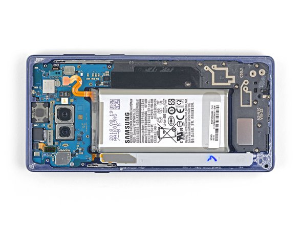
– With the tip of your trusty spudger, gently disconnect that orange ribbon cable linking the battery to the motherboard. You’ve got this!
Tools Used
Step 18

– Let’s get rolling! First off, grab your trusty screwdriver and carefully take out the nine 4 mm Phillips screws from the plastic cover near the battery. You’ve got this!

Step 20


The lower midframe easily clicks in and out like a pro!
– Slide the tip of a spudger into the top of the lower midframe. It’s gonna be tight, but keep going. You’ve got this!
– Gently pry the lower midframe away from the phone. Take your time, you don’t want to cause any damage.
– Remove the lower midframe. Woohoo! You’re making progress.
Tools Used
Step 21


– Time to get that front camera out – use the tip of a spudger to carefully pry the connector straight up and out of its socket. Take your time, it’s easier than you think!
– Now, grab those tweezers and gently remove the front camera. If you need help, you can always schedule a repair
Step 22


– Grab your trusty spudger and gently use its tip to disconnect the iris scanner from the motherboard. You’ve got this!
– Next, take your tweezers and carefully remove the iris scanner. Easy peasy!


Step 24


– Now it’s time to disconnect the display cable from the motherboard – simply use the flat end of a spudger to gently pry it loose. If you need help, you can always schedule a repair
Tools Used
Step 25


– Now, grab that trusty spudger and use the flat end to gently disconnect the touchscreen cable from the motherboard. It’s like untangling a headphone cord, but way cooler! Just be careful not to pull too hard. If you need help, you can always schedule a repair.
Tools Used
Step 26


– Grab that trusty spudger and gently slide the flat end under the charging assembly to give it a little nudge and disconnect it from the motherboard. You’ve got this!
Tools Used
Step 27


– Let’s get started by removing the three 4mm Phillips screws that hold the motherboard in place. Grab your trusty screwdriver and get to work!
– Take a closer look and you’ll notice triangles next to the holes, which will help guide you to the correct screw locations. If you need help, you can always schedule a repair
Step 28


Whoa there, watch those ribbon cables — keep ’em safe and sound! No need to pull that motherboard out if it gets snagged on anything, okay? Need some help? You can always schedule a repair!
– Grab your trusty spudger and gently nudge the motherboard up from the upper-left corner. You’ve got this!
– Now, with a careful touch, lift out that motherboard like it’s a precious treasure.
Tools Used
Step 29


– Go ahead and unscrew the 3.2 mm Phillips screw holding that headphone jack in place. You’re doing awesome!
Step 30


If the contact board is stubborn and doesn’t want to come apart, don’t worry! Just give it a little nudge with a drop of 90% isopropyl alcohol in the notch. Let it hang out for a bit, and it’ll loosen up that adhesive. Then, give it another try.
– Let’s get this party started! Slide the tip of your trusty spudger into the little notch near the headphone jack.
– Now, gently pry that contact board straight up to free it from its sticky situation. No worries, it’s just a little adhesive holding it in place. If you need help, you can always schedule a repair
Tools Used
Step 31


– Grab your trusty tweezers and gently pull out the headphone jack assembly. You’ve got this!
Tools Used