Replace Samsung Galaxy S4 Rear-Facing Camera Step-by-Step Guide
Duration: 45 minutes
Steps: 17 Steps
Heads up, team! Make sure you’ve got your tools ready and your workspace clear. We’re diving into this repair with style and a smile!
Rock on with this guide to swap out the rear-facing camera on your Samsung Galaxy S4. Getting a pesky ‘Camera failed’ message? First, try clearing the data in the Camera app via the Application manager and give your phone a quick reboot. Still seeing error messages? A factory reset might do the trick (but remember to backup your data first). If you’re still out of luck, consider reinstalling the Android OS. If all else fails, it might be time for a hardware replacement. You can also check the camera functionality by entering the Hidden/Test menu with *#0*#.
Step 1


– Use a plastic opening tool or even your trusty fingernail to gently pry in the little notch to the left of the rear camera, right near the power button. Let’s pop that open!
Step 2


– Grab the nearest corner to the divot on the rear case and gently lift it off your phone. Voilà, it’s off!
Step 3


– Nudge the microSD card a tad deeper into its cozy slot using the flat end of a spudger or your trusty fingernail until you hear that satisfying click.
– Once you hear the click, let go and watch the card spring out of its slot like a jack-in-the-box!
– Go ahead and remove the microSD card.
– For putting it back together, just press the microSD card back into its home until you hear that reassuring click.
Tools Used

Step 4


– Pop in a plastic opening tool, or even just your finger, into the notch of the battery compartment and give the battery a gentle upward nudge.
– Lift the battery out of your phone and voila!
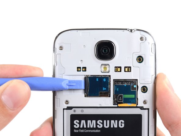
Step 5


– Grab a plastic opening tool or use your fingernail to push the SIM card a bit deeper into its slot until you hear a satisfying click.
– Once you hear the click, let go, and the card will pop right out.
– Take out the SIM card.
– When putting it back together, push the SIM card into the slot until you hear that click again.
Step 6

– Unscrew the nine 4.0 mm Phillips #00 screws that are keeping the midframe attached to the display assembly. Let’s get those little guys out!
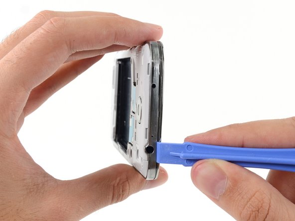
Step 7


– Begin on the side of the phone where the volume buttons are located. Place your plastic opening tool between the display glass’s chrome bezel and the wider chrome border. Look for the joining seam between these parts.
– Gently glide the opening tool along the seam to disconnect the plastic clips, continuing until they are all separated.
Handle with care! Gently pry just enough to unclip the plastic without flexing it too much—those midframe bezels are sensitive and might crack if they’re bent too far. Keep it cool and steady!
The midframe is snugly held in place by a bunch of sneaky plastic clips tucked behind the midframe’s chrome bezel. Hang tight! The upcoming steps will walk you through popping those clips to liberate the midframe.
Step 8


– Keep on prying around the phone’s corner—almost there!
– Glide your opening tool along the bottom seam, between the midframe and the display, popping open those pesky plastic clips.
Step 9


– Next up, let’s gently pry around the corner near the power button. Feel the magic as you lift!
– Continue the fun by sliding your opening tool along the seam. Keep the groove going!
Step 10

Now’s a great time to give that plastic opening tool one more victory lap around the device’s border to ensure all those sneaky clips are totally unhooked.
– Keep cruising with that opening tool around the top edge of your phone, popping off those last pesky clips. You’re just about to liberate the midframe from the display assembly. Almost there, champ!


Step 12


– Grab your trusty spudger and gently disconnect the USB board connector. Pop it off like a pro!
– Next up, unplug the front-facing camera cable connector. Just a little tug!
– Finally, disconnect the earpiece speaker assembly cable connector. You’re doing awesome!
Tools Used
Step 13


– Unplug the headphone jack assembly cable connector.
– Unplug the display/digitizer cable connector.
– Unplug the antenna cable connector.
Step 14

– Unscrew that lonely 2.4 mm Phillips #00 screw holding onto the motherboard assembly like it’s the last cookie in the jar!
Step 15


Grab the motherboard by the edges—like it’s a hot slice of pizza—and gently lift it out, avoiding any cable traps. Keep it cool and snag-free!
– Carefully coax the motherboard out of its cozy home.

Step 17

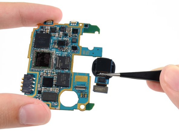
– Grab your tweezers or just use your fingers to shimmy that rear-facing camera out of its cozy little nook on the motherboard.
Tools Used