Replace Sony PlayStation 5 Pro Front Trim: Step-by-Step Guide
Duration: 45 minutes
Steps: 32 Steps
Get ready to breathe new life into your PlayStation 5 Pro by replacing the front trim assembly. This crucial component includes the power button, USB-C board, and antenna – and with this clear, step-by-step guide from Salvation Repair, you’ll be navigating the process like a pro in no time. If you’re feeling stuck or unsure, don’t worry – we’ve got you covered. Just follow along, and you’ll have your console looking and working like new again.
Step 1


Before diving into your repair adventure:
– First things first, power down your PlayStation and detach all those pesky cables and accessories. They’re really just cramping its style!
– Next, give it a little space! Remove any stands that might be giving your console a lift and lay it down gently on its right side, like it’s taking a well-deserved nap.
Step 2


The console cover is held in place with hooks at the back and clips at the front.
You’ll hear satisfying ‘pops’ as the clips come loose.
– To pop off the cover, give that front edge a solid tug to unclip it. You’ve got this!
– Now, go ahead and take off the cover.
Step 3


– Keep the momentum going! Use the same straightforward technique to gently lift off the three other covers.
– When it’s time to put a cover back on, simply align the hooks into their designated spots along the back edge, and give the front edge a good press until those clips snap back into action!
Step 4


– Grab your trusty T8 Torx Security screwdriver and remove the two 21.5mm-long screws holding the power supply.
– Flip your PlayStation over.
Step 5


Stay organized and keep track of each screw, making sure it ends up back where it started. This will save you a headache later on and ensure everything goes smoothly.
– Grab your trusty Phillips screwdriver and give that 17.1 mm long screw securing the expansion slot cover a little twist! It’ll come right off.
Step 6


– Gently pry up the expansion slot cover located near the notch by the screw hole using your fingers, and pop it off like it’s a lid on a can of soda.
Step 7


Don’t worry, it’s just a little bit of glue holding that cover in place. It’s like a friendly hug for the phone!
– Gently pry off the plastic cover that’s keeping those fan cables under wraps—your fingers are the perfect tools for the job!
– When it’s time to put everything back together, simply press that plastic piece snugly into place so it sticks with the old adhesive. If it’s being a little stubborn, feel free to use some double-sided tape to keep it secure.


Step 9


Having a tough time? Just grab the cables close to the connector head and give them a gentle tug.
– Grab the white connector head of the fan cables and yank it straight up and out of its socket.
– When you’re putting it back together, align the connector with its socket and use a spudger’s flat end to press down on the edges until it slides fully into place.
Tools Used

Step 10


– Let’s get started by using a T8 Torx Security screwdriver to remove the four screws that hold the fan in place:
– First, you’ll find one 31.7 mm-long screw – carefully remove it
– Next, locate two 21.5 mm-long screws and take those out as well
– Lastly, remove one 11.5 mm-long screw to completely free the fan
Step 11


Now’s the perfect time to give that fan a little TLC! Grab a fresh cloth and some compressed air, then blow away any dust bunnies or grime lurking in there. Your device will thank you for it!
– Grab the fan by its vents with your fingers and gently lift it straight up to remove it – easy peasy!
– When you’re putting everything back together:
– Carefully insert the fan, making sure its cables are close to their connector, and you’re good to go!
Tools Used

Step 12


Don’t sweat those warranty stickers! Here in the US, they’re no big deal thanks to the Magnuson–Moss Warranty Act. And even if you’re somewhere else, don’t let them scare you. We’ve got your back.
– There’s a sneaky little tamper-evident sticker covering one of the screws on the inner shell’s right side. Time to give it some TLC!
– Grab your trusty tweezers and gently peel back that sticker to reveal the hidden screw. You’ve got this!


Step 14


– Grab your trusty T8 Torx Security screwdriver and give those 10 screws holding the right-side inner shell a spin! You’ll find:
* Four 18.8mm-long screws
* Two 18.6mm-long screws
* Four 31.7mm-long screws
Step 15


– Time to free that inner shell! Give it a gentle lift from the right side and watch it pop right off.
Step 16


If you’re stuck, gently rock the connector from side to side to loosen it up. It’s an easy fix, and you’ve got this!
– Grab your trusty angled tweezers and get a firm grip on the CMOS board connector. Hold them close to the connector to get a good handle on it.
– Now, carefully pull the connector straight up and out of its socket. This should disconnect it nicely.
Tools Used

Step 17


– Now, grab that CMOS board and give it a little lift with your fingers. Gently pull it towards the center of your console, and watch it slide right out! It’s like magic.
– If your new board doesn’t have a cable, just transfer the original one over. Easy peasy!
Step 18


– First up, grab your trusty spudger and gently slide it under the metal neck of one of the coaxial connectors for the antenna cable. Lift straight up like you’re lifting a prize trophy to disconnect it.
– Now, let’s keep the rhythm going—do the same thing to disconnect the other antenna cable. You’ve got this!
– When it’s time to put everything back together:
– Keep an eye on those handy markings on the board to guide you in reconnecting the antenna cables correctly. Remember: blue cable goes to the socket labeled RB, and white cable gets cozy in the RW socket.
– For reconnecting, hold the metal connector head right above its designated socket and press down with the flat end of the spudger until you hear that satisfying snap! No need to force anything—if it’s being fussy, just reposition the connector and give it another go.
Tools Used


Step 20


– Gently coax the antenna cables out of their clips on the metal shield – just use your fingers, it’s easy!
– Now, carefully move those antenna cables to the side of your PlayStation, so they’re nicely out of the way and won’t get tangled up in the rest of the repair process.
Step 21


– Slide the flat end of your spudger under the curve of the copper pipes, right by the bottom edge of the heat sink.
– Go ahead and nudge the heat sink up with your spudger, giving it a gentle but determined push to help it break free from the thermal paste’s hold.
– If the heat sink seems a bit stubborn and won’t come off completely, flip your spudger and try to lift up the bottom edge on the opposite side of those metal fins.
Alright, time to get groovy with that heat sink! You’ll see those little fins, they’re like the heat sink’s tiny fingers, gripping onto the metal shield. That gooey thermal paste is like a magical bond, keeping them together. Now, depending on how old your device is and how well the paste is doing, you might need to give those fins a little nudge to get them loose. Just remember, be gentle! If you need any help, you can always schedule a repair.
Tools Used
Step 22


Those heat sink fins are pretty sharp! Be careful not to grab them. You don’t want to get a little nip, right?
Before you wipe off any old thermal paste, make a mental note of its location and how much is on the metal shield. This way, you’ll know just the right amount to use when you apply the new stuff.
– Grab that heat sink by its cool copper pipes and give it a gentle lift to remove it.
– Now for the fun part! Get ready to put your reassembly skills to the test.
– Using the flat end of a spudger, scrape up any leftover thermal paste like you’re a master chef cleaning your kitchen.
– Let’s get rid of any remaining thermal paste residue. Grab some high‑concentration (>90%) isopropyl alcohol and a microfiber cloth and give that heat sink a good wipe down.
– Time to apply a fresh coat of thermal paste where the old one was. You got this!
– Push that heat sink back into place with a firm, confident press. You’re almost there!
Tools Used

Step 23


– Let’s get started by removing the six screws using a T8 Torx Security screwdriver – it’s time to take apart your device!
– First, locate the 11.5 mm-long black screw that’s holding the main board assembly in place, and gently remove it.
– Next, find the 28.7 mm-long screw that’s securing the interconnect cable cover, and carefully take it out.
– Now, remove the four 7.5 mm-long screws that are also holding the interconnect cable cover – you’re making great progress!
Step 24


– Let’s get that cover off! Time to remove the interconnect cable cover.
Step 25


– Time to channel your inner engineer! Grab your trusty spudger and gently press down on that metal bar sitting on the interconnect cable’s socket.
– While you’re holding that bar down, use your fingers or some tweezers to give the plastic pull tab a nice firm grip. Slide that cable out like a pro!
– As you put everything back together, make sure to insert the interconnect cable back into its socket until you hear it snap in. You’ve got this!
Tools Used
Step 26


The power supply is connected to the main board assembly by some metal prongs that plug into the bottom left corner, so be careful when lifting the assembly.
No worries, your PlayStation’s plastic housing will likely flex a little bit when you lift the assembly. It’s totally normal, just go with it!
– Gently lift the bottom left corner of the main board assembly off its gray plastic post. Hold it up as we get ready for the next step.
Step 27


It might take some serious oomph to pull these apart.
– Get a good grip on the main board assembly with one hand – you’ve got this!
– With your other hand, carefully slide your finger between the assembly and the power supply to get ready for the separation.
– Gently push down on the power supply and lift the assembly – they should start to come apart nicely.
– When it’s time to put everything back together, press down firmly on the bottom left corner of the main board assembly to make sure it’s securely connected to the power supply. If you need help, you can always schedule a repair
Step 28


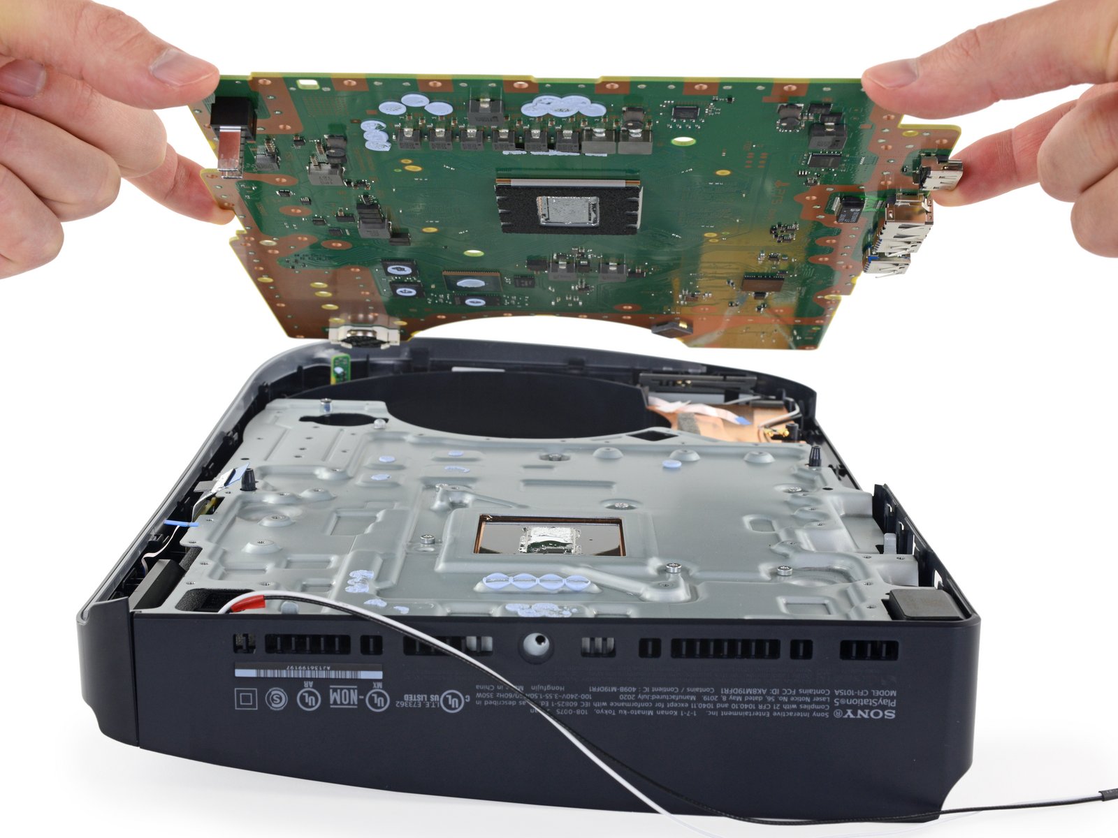
Be gentle with that main board assembly – avoid grabbing it by the copper heat pipes or fins, since they’re pretty fragile and can get damaged easily.
Don’t let that interconnect cable get tangled up under the main board assembly when you’re putting it back in place. Keep an eye on it and make sure it’s nice and clear.
– Get a good grip on the plastic housing with one hand – you’ve got this!
– Now, use your free hand to grab the upper edge of the main board assembly and gently lift it out of the plastic housing. Easy does it!
– When it’s time to put everything back together:
– Carefully lower the assembly into its spot, making sure its prongs slide into their socket on the power supply and the cutouts fit nicely over their alignment posts. If you need help, you can always schedule a repair
Step 29
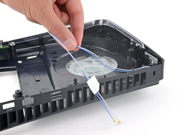

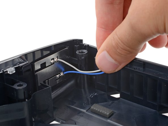
– Gently pull up on both antenna cables to release them from their clips along the rear edge of your PlayStation – it’s like freeing them from their cozy little homes!
– When you’re putting everything back together, make sure to tuck the cables neatly back into their clips on the rear edge of the frame, so they’re secure and out of the way.
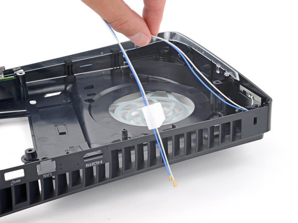
Step 30

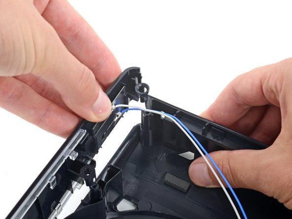
– Gently guide both antenna cables downward and slide them out from their clip in the top right corner of the plastic housing. You’ve got this!
Step 31

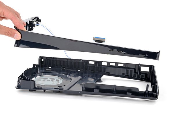
– With one hand, get a good grip on the right edge of the plastic housing – you’ve got this!
– Now, use your free hand to carefully lift the top edge of the front trim. You’ll know it’s working when you hear those three plastic clips release.
– When it’s time to put everything back together, simply push the front trim onto the frame and listen for the satisfying snap of the clips falling into place.
Step 32

– Reassemble your device by following the steps in reverse.
– Recycle your e-waste responsibly at an R2 or e-Stewards certified recycler.
– Troubleshooting got you stumped? Check out our Answers community for help.
– Cancel: I did not finish this guide.
–
Success!