Samsung Galaxy Note Display Assembly Replacement Guide – DIY Tutorial
Duration: 45 minutes
Steps: 31 Steps
Let’s get that cracked screen fixed! This guide will walk you through replacing the front panel display assembly on your Samsung Galaxy Note. Ready to give your phone a new lease on life? Let’s do this! If you need help, you can always schedule a repair.
Step 1


– Let’s pop that stylus cap off! Grab it by the top and gently pull it out of its home in the midframe.
Step 2


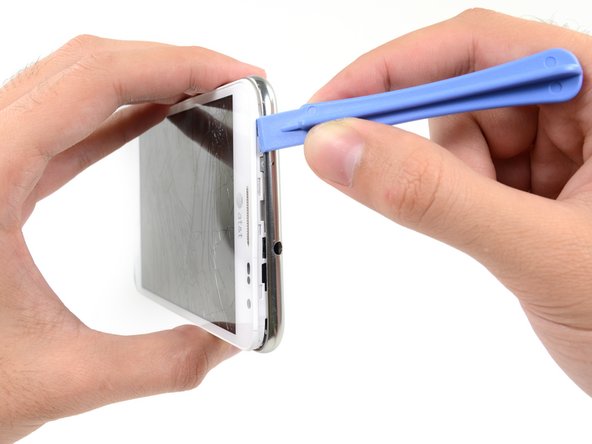
– Let’s get this party started! Use a plastic opening tool, or your trusty fingernail, and gently pry in the little divot to the right of the rear-facing camera. You’ll find it near the volume rocker. Don’t be afraid to give it a little love. If you need help, you can always schedule a repair.
Step 3


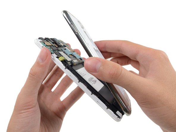
– Let’s get started by carefully lifting and removing the rear case from your phone. This is the first step in giving your device a brand new lease on life. If you need help, you can always schedule a repair


Step 5


– Gently nudge the microSD card a bit deeper into its cozy home with the flat end of a spudger or your trusty fingernail until you hear that satisfying click.
– Once you hear the click, let go of the card and watch it spring back out like it’s ready for action.
– For putting things back together, just slide the microSD card back into its slot until you hear it click into place. Easy peasy!
Tools Used

Step 6

– Alright, let’s get that microSD card out of its little home in the midframe. It’s just a quick pop-out. Easy peasy!
Step 7


– Time to set that SIM card free. Use a plastic opening tool or your fingernail to gently push it out of its compartment. If you need help, you can always schedule a repair
Step 8


– Gently push the SIM card out with your thumb until it’s free, then give it a little wiggle to remove it from the device. If you run into any trouble, remember, you can always schedule a repair.
Step 9

– Unscrew the nine 3.4 mm Phillips #00 screws that are holding the midframe snugly to the display assembly. Let’s get that midframe off with a little finesse!
Step 10

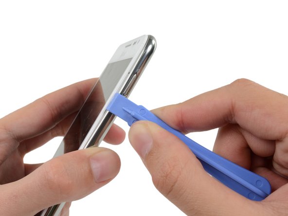
– Alright, let’s get this party started! Slide your trusty plastic opening tool in between the midframe and the front panel assembly, right next to the power button. Give it a gentle pry, and you’ll be on your way to techy success!
Step 11


– Let’s get this party started! Gently slide the plastic opening tool down the seam. It’s like a little dance party for your phone.
Step 12
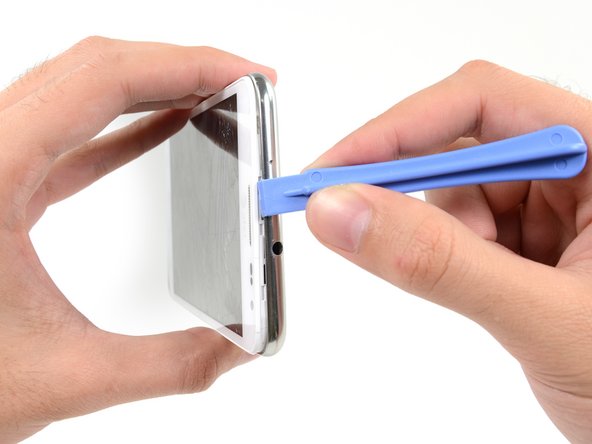

– Start by inserting your trusty plastic opening tool to the left of the headphone jack, where the midframe and display assembly meet – it’s time to get this repair started!
– Now, gently slide the opening tool along the top edge of your phone, taking your time to get a good grip.
– Keep running that plastic opening tool around the perimeter of your phone until the midframe is separated – you’re making great progress! If you need help, you can always schedule a repair

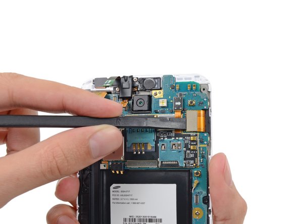
Step 14


– Now it’s time to disconnect the display cable connector – use the flat end of a spudger to carefully pry it loose. If you need help, you can always schedule a repair
Tools Used
Step 15


– Let’s get started – use a spudger to carefully disconnect the front-facing camera assembly cable connector.
– Next, locate and disconnect the headphone jack/earpiece speaker assembly cable connector – it’s an easy step.
– Now, gently disconnect the digitizer cable connector to move forward with your repair. If you need help, you can always schedule a repair
Tools Used

Step 17

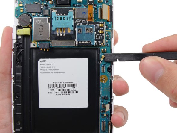
– Pop out those two 3.4 mm Phillips #00 screws that are locking down the motherboard to the display assembly.
Step 18


– Gently detach the motherboard assembly from the display assembly, like peeling a banana—smooth and easy!
Step 19

– Let’s get started by removing the two 3 mm Phillips #00 screws that hold the upper display assembly bracket in place. If you need help, you can always schedule a repair
Step 20


– Time to get a little handy – use a pair of tweezers or your fingers to carefully remove the upper display assembly bracket. If you need help, you can always schedule a repair
Tools Used


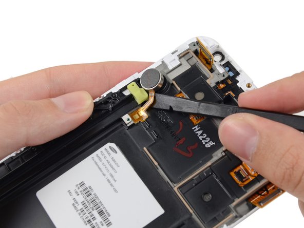
Step 22

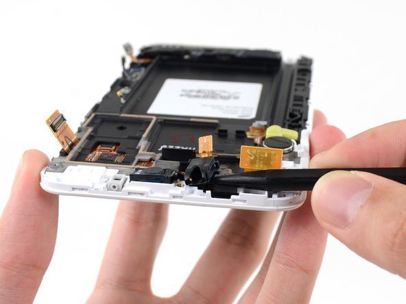
– Gently use the tip of a spudger to nudge the headphone jack/earpiece speaker assembly out of its cozy spot in the display assembly. You’ve got this!
Tools Used
Step 23

– Grab some tweezers or just use those nimble fingers of yours to gently detach the headphone jack/earpiece speaker assembly. You’ve got this!
Tools Used
Step 24

– Alright, let’s get those speakers out! You’ll need to give those three 3 mm Phillips #00 screws a little spin to get the speaker enclosure off the front panel assembly. It’s like a mini-treasure hunt for your speakers! If you need help, you can always schedule a repair.
Step 25

– Time to give that speaker enclosure some air! Gently lift it away from the display assembly. You got this!


Step 27


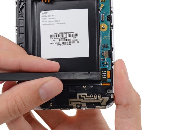
Gently slide the spudger in at a low angle to keep the USB board safe from bends or damage. You’ve got this!
– Let’s get that USB board outta there! Take your handy-dandy spudger and gently slide the flat end under the USB board. You’ll feel it start to separate from the display assembly. Easy peasy!
Tools Used
Step 28

– Time to get started – carefully remove the USB board to begin the repair process. If you need help, you can always schedule a repair