Samsung Galaxy Note10+ 5G Daughterboard Replacement Guide
Duration: 45 minutes
Steps: 19 Steps
Hey there, tech enthusiast! Let’s tackle this Samsung Galaxy Note10+ 5G daughterboard swap. It’s the board that houses the USB-C charging connector, so you’re gonna be back in the game in no time. This guide’s based on the non-5G Note10+, so you might notice a few minor visual differences, but don’t sweat it, the steps are all good. If you need any help along the way, you can always schedule a repair.
Step 1

Before you start taking things apart, make sure your phone is completely powered off. Let’s get started with your repair journey at Salvation Repair. If you need help, you can always schedule a repair
You can use a hair dryer, heat gun, or hot plate for some extra warmth, but keep an eye on it! Too much heat can be a real bummer for your phone’s display and internal battery, so let’s avoid any heat mishaps.
– Grab your iOpener and give the left edge of the rear cover a nice, warm hug for a minute.
Tools Used

Step 2


Got a badly cracked rear cover? No worries, just slap some clear packing tape on it and the suction cup should stick like a charm. Or, if you’re feeling extra handy, you can use some super strong tape instead. And if all else fails, a little superglue can work wonders to get that suction cup to stay put on the broken cover.
Having some trouble with this step? Don’t sweat it, it can be a bit tricky depending on your phone’s age. Just apply some extra heat to the edge and try again. If you’re still having issues, remember that you can always schedule a repair with the pros at Salvation Repair.
– Grab a suction cup and stick it to the warm edge of the rear cover, getting as close to the edge as you can.
– Give that suction cup a good, steady pull to open up a little gap between the rear cover and the frame.
– Slide the tip of an opening pick into that gap you’ve just created.
Step 3


Be careful not to insert the opening pick too far into the phone – about halfway is the sweet spot. Going further could put those internal components at risk, and we want to keep them safe and sound. If you need help, you can always schedule a repair
– Gently glide the opening pick down the left edge until you reach the bottom left corner, slicing through that adhesive like a pro.
– Keep the pick snugly in the bottom left corner to make sure that pesky adhesive doesn’t seal itself back up on you.
Step 4


The rear cover will start to come off as you work your way around the edges of the phone. It’s like the phone is giving you a high five for being so awesome at this! Keep going, you’re doing great! If you need help, you can always schedule a repair
– Now it’s time to repeat the heating and cutting process for the remaining three sides of your phone – just like you did before, but on the other sides. Keep it up, you’re doing great!
– As you move on to the next side, make sure to leave an opening pick in place to prevent the adhesive from sneaking back in. You’re making progress, and that’s something to be proud of! If you need help, you can always schedule a repair
Step 5


Alright, superstar, time for the big reveal! Turn on your device and make sure everything’s working like a charm before you seal it up tight. If you need a helping hand, you can always schedule a repair.
– Gently lift the rear cover straight up and say goodbye to it for now!
– Check out this guide to put that rear cover back on and make it stick like it’s never left.
– Using Tesa tape to get your parts back together? No worries, just follow this handy guide.
Step 6

– Let’s get started by removing the five 4mm screws that hold the wireless charging coil in place – just grab your trusty Phillips screwdriver and you’re all set. If you need help, you can always schedule a repair


Step 8


– With the metal shield held up and out of the way, gently pry up the battery connector using the pointed end of a spudger to disconnect it. It’s like giving the battery a little high-five! You’re doing great. If you need help, you can always schedule a repair
Tools Used

Step 9


– Now it’s time to get a little more hands-on – use the pointed end of a spudger to carefully disconnect the wireless charging coil connector from the motherboard. If you need help, you can always schedule a repair
Tools Used
Step 10


Whoa, the wireless charging coil is gluestick to your phone! Don’t worry, just give it a gentle nudge and it’ll be back to charging in no time. If you need help, you can always schedule a repair.
– Give that metal shielding a little nudge and tilt it up so you can get a good grip. You got this!
– Now, let’s gently peel that wireless charging coil up and away from the device. It’s like taking off a cozy sweater.
– Time to remove the wireless charging coil. You’re doing great!
Step 11

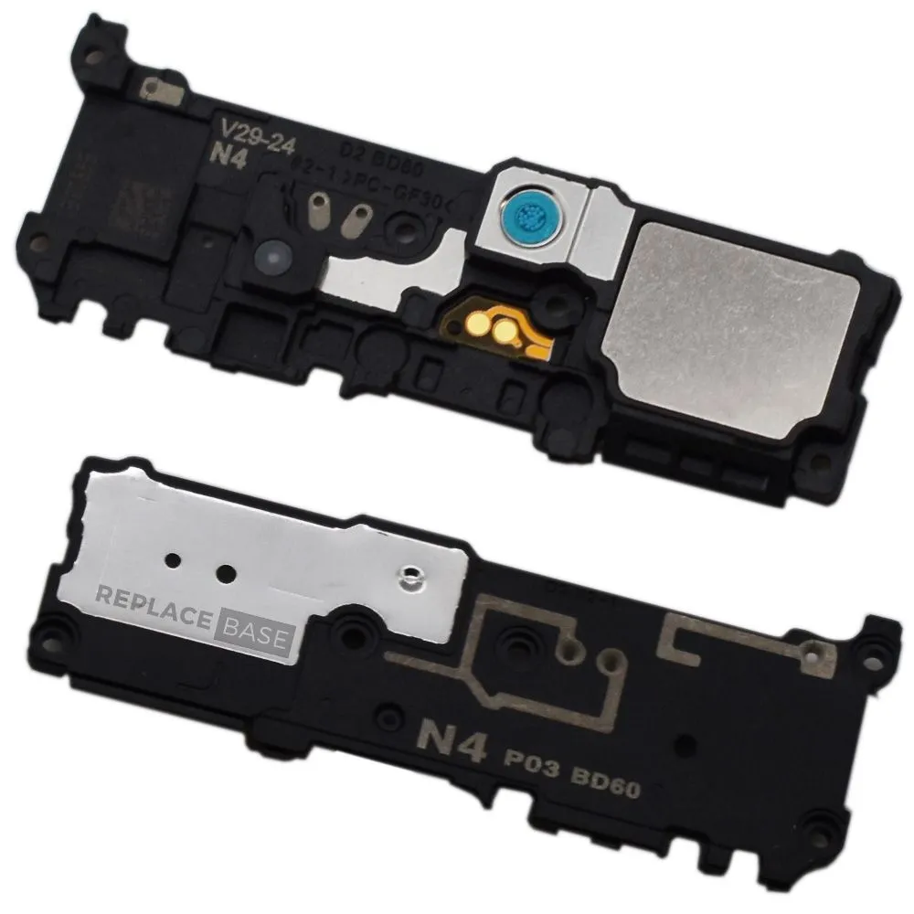
– Grab your trusty Phillips screwdriver and get ready to tackle those five 4 mm screws holding the loudspeaker in place. You’ve got this!


Step 13


– Time to get started! Use the pointed end of a spudger to carefully disconnect the main interconnect cable from the motherboard.
– Next, gently disconnect the secondary interconnect cable from the motherboard. If you need help, you can always schedule a repair
Tools Used
Step 14


– Time to get started! Use the pointed end of a spudger to carefully disconnect the main interconnect cable from the daughterboard.
– Next, gently disconnect the secondary interconnect cable from the daughterboard. If you need help, you can always schedule a repair
Tools Used
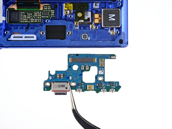
Step 15

– Let’s get started by removing the main interconnect cable. This is a crucial step, so take your time and make sure it’s done correctly. If you need help, you can always schedule a repair
Step 16


Hey there! Just a quick heads up: steer clear of the secondary interconnect cable! It’s snugly attached to the side 5G mmWave antenna, so let it be for now.
– Carefully pry the secondary interconnect cable away from the battery using a spudger or your fingers – don’t worry, it’s easier than it sounds. If you need help, you can always schedule a repair
Tools Used
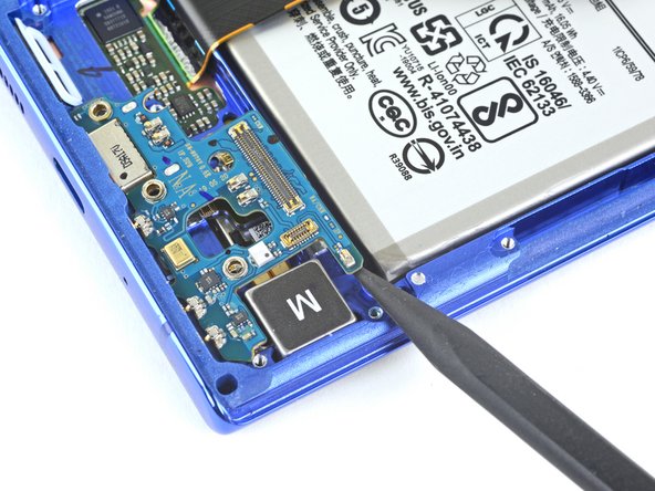
Step 17

– Grab your trusty Phillips screwdriver and go ahead and unscrew those three 4 mm screws holding the charging assembly daughterboard in place. You’ve got this!