Samsung Galaxy Note20 Ultra Motherboard Replacement Guide
Duration: 45 minutes
Steps: 32 Steps
Hey there! To keep things safe and sound, make sure to let your battery dip below 25% before you dive into disassembling your phone. You’ve got this!
Alright, let’s get this motherboard swap party started! First things first, make sure your phone’s battery is chillin’ below 25%. We don’t want any unexpected heat waves during this adventure. A swollen battery? No worries, just be extra careful. If you’re feeling a little overwhelmed, you can always schedule a repair and let our pros take care of it. We’ve got your back!
Step 1


No worries if you’ve accidentally poked the SIM eject tool into the microphone hole! You’re probably in the clear and your microphone is just fine.
– Grab your trusty SIM eject tool, a bit, or even a straightened paper clip. Now, gently insert it into the SIM card tray hole at the top edge of your phone.
– Give it a little push – not too hard, but firm enough to pop that tray out.
– Carefully pull out the SIM card tray and voilà! You’re all set.
Step 2

– Let’s warm up that rear cover! Grab your iOpener, heat it up, and apply it to the left side of the rear cover for a minute. That’ll make things a little easier to work with.
Hey there! Don’t forget to give your phone a little vacay by powering it off before you start any disassembly. A little heat can be helpful, but no need to blast your device – keep the heat low to avoid any accidental damage to the screen or battery. If you need help, you can always schedule a repair!
Tools Used

Step 3


Hey there, champ! Don’t go crazy with that opening pick! Just gently slide it in, no more than 5mm. We wouldn’t want to hurt any of the phone’s delicate innards, right? If you need help, you can always schedule a repair.
If your back glass is busted, covering it with a layer of clear packing tape might help the suction cup stick. Or, you can try using super strong tape instead of the suction cup. If you’re still having trouble, you can always schedule a repair.
Depending on how old your phone is, getting that back glass off might be a little tricky. If you’re having trouble, just add a little more heat to the edge and give it another try.
– Let’s get that back cover off! Stick a suction cup to the heated edge of the rear cover, right on that edge, baby.
– Now, give that suction cup a good pull! You want to create a little space between the rear cover and the frame. Nice and steady now.
– Time to slip in an opening pick into that little gap we just created.
Step 4


– Let’s get this party started! Slide the opening pick along the left edge, working your way towards the bottom left corner. It’s like a dance, but with a tool! 😎
– Keep that pick chillin’ in the bottom left corner. We don’t want that adhesive getting cozy again, now do we? 😉
Step 5


Hey, careful with that opening pick! Keep it chill and don’t go deeper than 5 mm into the phone. We don’t want to get too close to the phone’s internal parts. If you need help, you can always schedule a repair.
Slide in each new opening pick into the little gaps created by the picks you’ve already placed in the corners. It’s like giving your device a gentle nudge!
– Keep the momentum going by heating and slicing through the adhesive on the last three sides of the rear cover.
– As you work your magic, pop an opening pick into each corner to keep that sticky stuff from sealing back up.
– Glide an opening pick all around the edge of your phone to free any adhesive that might be playing hard to get. If you encounter some stubborn spots, just give it another heat-up!
Step 6


– Gently lift the rear cover straight up to take it off.
Step 7


Be gentle! When prying, make sure to slide in just under the connector’s edge. You want to avoid causing any trouble to the socket or the nearby components. Keep it cool, and you’ll be golden!
– Use the trusty spudger to carefully pry up and disconnect the wireless charging coil press connector – it’s like a little puzzle piece waiting to come loose.
– To put it all back together, line up the press connector and gently press one side until you hear that satisfying click. Then, repeat on the other side. Just remember, don’t press down on the middle or you might end up with bent pins and a bigger problem on your hands. If you need help, you can always schedule a repair
Tools Used

Step 8


– Now, let’s gently wiggle that white press connector loose. Use the pointed end of your spudger to pry it up from the bottom right corner of the motherboard shield. It’s like giving it a little high five!
Tools Used
Step 9

If these screws are still hanging on for dear life, it might take a little extra elbow grease to get them off since they’ve got some threadlocker doing its job. No worries though, you’ve got this!
As you dive into this repair adventure, keep an eye on each screw and make sure it finds its way back home—just like a boomerang!
– Let’s get started by removing the six 4.0 mm screws that hold the motherboard shield in place – just grab a Phillips screwdriver and you’re all set. If you need help, you can always schedule a repair
Step 10


Hey there, just a heads-up! The motherboard shield has some pretty sharp edges, so be careful when handling it. Take your time and you’ll be golden.
– Grab your trusty tweezers and gently lift up the motherboard shield.
– Now, get a grip on that motherboard shield with your fingers. You got this!
Tools Used

Step 11


The wireless charging coil is stuck to the device with a bit of adhesive, making it easy to remove and replace when you’re ready to get your device back in top shape. If you need help, you can always schedule a repair
– Gently lift the wireless charging coil away from the device like you’re peeling a banana, and voilà! It’s free!


Step 14

– Let’s get started by removing the four 4.0 mm screws that hold the earpiece speaker in place – just grab your trusty Phillips screwdriver and you’re all set. If you need help, you can always schedule a repair
Step 15


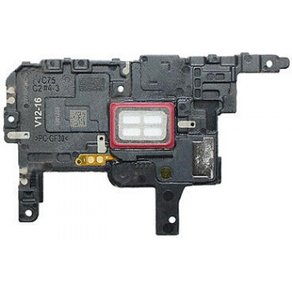
Alright, let’s get that earpiece speaker attached! It’s just a little clip right along the top edge of the frame. Easy peasy.
– Grab your trusty spudger and gently slide the pointed end into the little hole marked by a tiny triangle on the right side of the earpiece speaker. It’s like finding the secret door to the tech treasure!
– Now, use that spudger magic to carefully pry up and loosen the earpiece speaker from the frame. Just think of it as giving it a little nudge to say, ‘Hey, time to come out!’
Tools Used
Step 16


– Time to give that earpiece speaker a little lift! Gently remove it from its spot. You got this!
Step 17

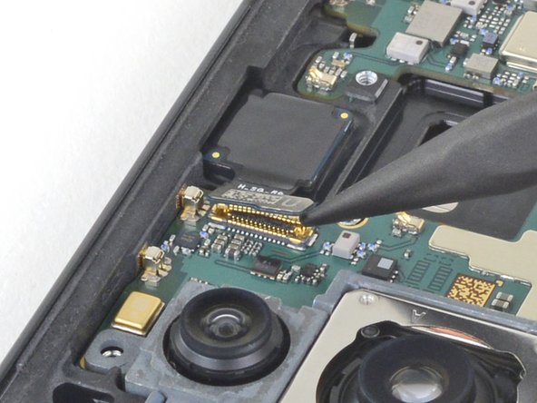
– Grab your trusty spudger and gently use the pointed end to unplug the front-facing camera cable from the motherboard. You’ve got this!
Tools Used
Step 18


– Grab that trusty spudger and use its pointed end to carefully disconnect the display cable from the motherboard. You’re doing great!
Tools Used
Step 19
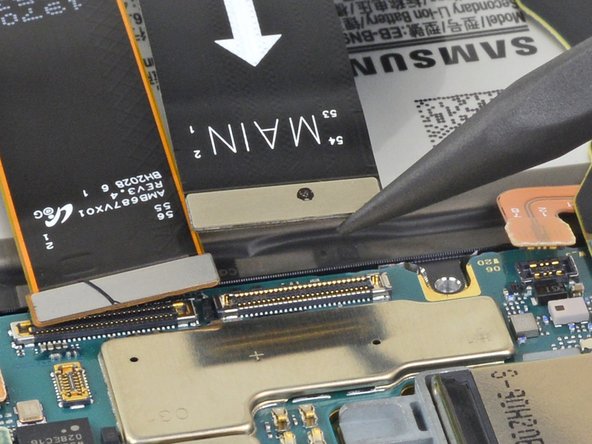

– Grab your trusty spudger and use its pointed end to carefully detach the main interconnect cable from the motherboard. You’ve got this!
Tools Used
Step 20


– Grab your trusty spudger and gently use its pointed end to disconnect the secondary interconnect cable from the motherboard. You’ve got this!
Tools Used
Step 21


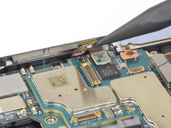
– Time to give those cables a little break! Use the pointed end of your spudger to gently disconnect the touch layer cable from the motherboard.
– Now, let’s disconnect that green press connector. Use the pointed end of your spudger to give it a little nudge away from the motherboard. You’re doing great!
Tools Used
Step 22
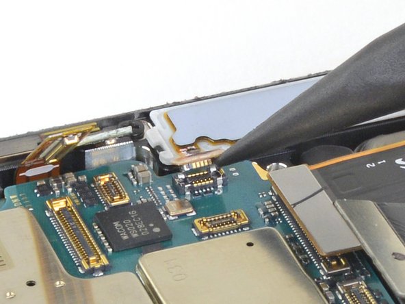

– Now, grab that spudger and its pointy end. We’re gonna gently detach the S-Pen press connector from the motherboard. It’s like giving it a little high five, but with a tool instead of your hand.
Tools Used
Step 23

– Grab your trusty Phillips screwdriver and tackle those two 4.0 mm screws holding the motherboard snugly in the frame. You’ve got this!
Step 24

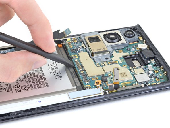
– Let’s give that motherboard a little wiggle room! Slide the flat end of your spudger under the bottom edge of the motherboard.
– Now, gently pry upwards to loosen the motherboard from the frame. You’re almost there!
Tools Used
Step 25
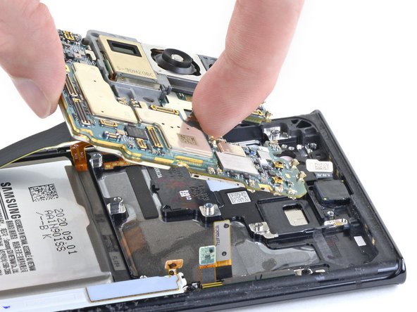

Hey, be super careful when you’re taking out the motherboard! Don’t go rough on those press connectors and their cables, they’re pretty sensitive.
– Now it’s time to carefully lift the motherboard out of the phone. Take your time and make sure it’s completely free from any obstructions. If you need help, you can always schedule a repair
Step 26

– Alright, when you’re popping that motherboard back in, make sure no cables are playing hide-and-seek underneath. Pay special attention to these seven areas:
– Secondary interconnect cable
– Battery cable
– Main interconnect cable
– Display cable
– S-Pen cable
– Touch layer cable and green press connector
– Front-facing camera cable
Step 27


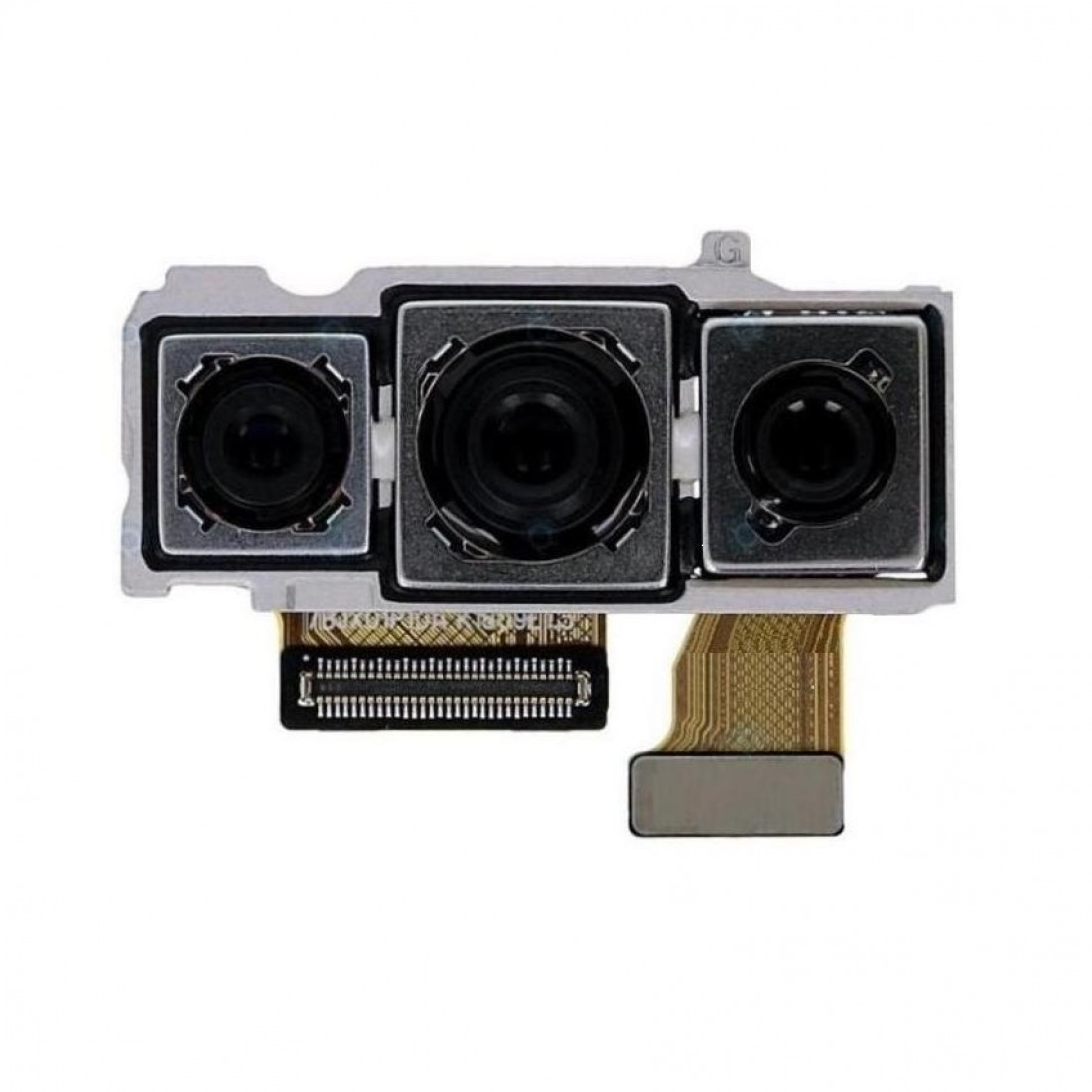
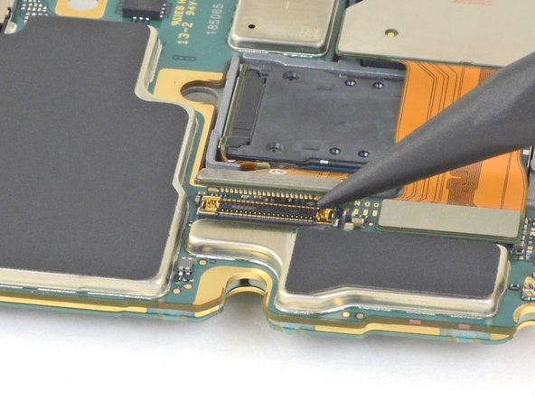
– Grab your trusty spudger and gently use its pointed end to disconnect the ultra wide camera from the motherboard. You’re doing great!
Tools Used
Step 28

– Hey, tech-savvy friend! Let’s disconnect that telephoto camera from the motherboard using the spudger’s pointy end. It’s like playing a game, but with your devices! 😉 If you need help, you can always schedule a repair.
Tools Used
Step 29


– Grab your trusty spudger (the pointed end, of course) and give that wide-angle camera a little nudge to disconnect it from the motherboard. You got this!
Tools Used
Step 30

Keep that ribbon cable happy by not bending it more than 90 degrees. Too much flexing might just hurt its feelings!
– Give that ultra wide camera ribbon cable a little bend, just enough to gently nudge it away from the motherboard. This will let you take out the rear camera assembly without any drama.
Step 31

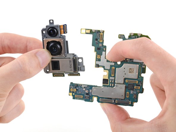

The rear camera assembly is gently glued to the motherboard, sitting snugly to the right of the telephoto camera. Just a little adhesive to keep it cozy!
– Gently detach the rear camera assembly from the motherboard. You’ve got this!
– When it’s time to put everything back together, just remember to use this guide if you’re working with a pre-cut adhesive card to attach that shiny new rear camera assembly to the motherboard.