Samsung Galaxy Note20 Ultra Rear Camera Replacement Guide
Duration: 45 minutes
Steps: 31 Steps
Hey there! Safety first, always. Before you dive into this repair, give your battery a little break and let it chill below 25%. You’ll be glad you did. 😊 If you need help, you can always schedule a repair.
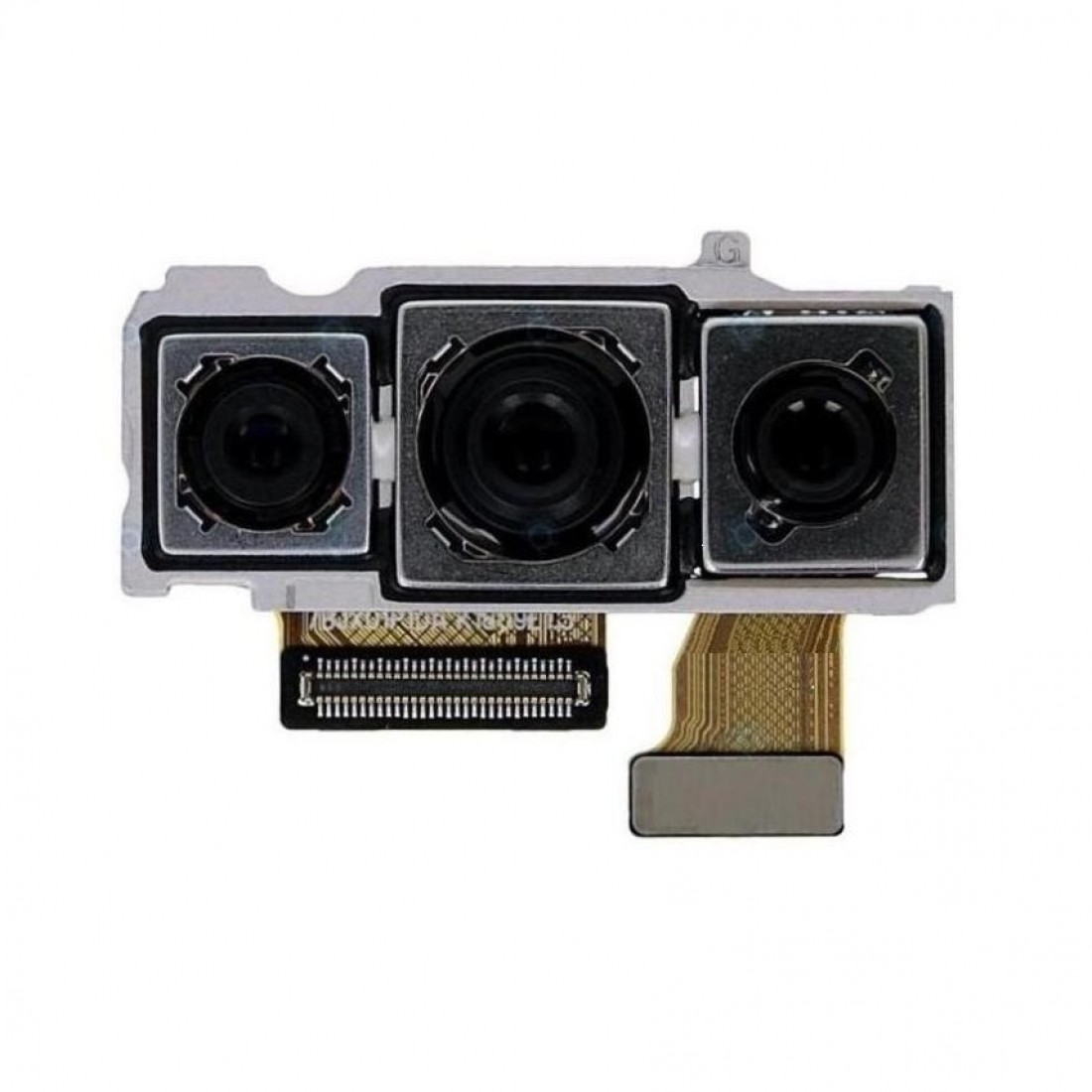
Ready to tackle the rear camera assembly replacement on your Samsung Galaxy Note20 Ultra? You’ve got this! The rear camera assembly includes an ultra wide camera, a wide-angle camera, and a telephoto camera – a whole photography squad right there! Before you dive in, make sure to drain your battery below 25%. This little precaution keeps things safe and sound, reducing the chances of a thermal surprise if your battery takes a hit during the process. And remember, if your battery looks like it’s been on a little too much vacation (you know, swollen), be cautious and take the proper steps. If you need help, you can always schedule a repair.
Step 1


No need to panic if you accidentally popped the SIM eject tool into the microphone hole! Chances are, your microphone is still just fine.
– Let’s pop out that SIM card! Find the tiny little hole on the top edge of your phone. It’s the SIM card tray hole.
– Now, grab your SIM eject tool, a paperclip, or even a straightened-out paperclip. You’re the boss! You’ll need it to gently nudge the tray out.
– Press firmly but gently on the tool. The tray should pop right out. Go ahead and take it out! You’re almost there.
Step 2

Before you start, make sure to completely power down your phone – it’s time to get started on this repair journey!
You can use a hair dryer, heat gun, or hot plate to get the job done, just be careful not to overheat your phone – the screen and battery are sensitive to heat, so let’s keep things cool.
– Let’s get started by heating up an iOpener and applying it to the left side of the rear cover for about a minute. If you need help along the way, you can always schedule a repair
Tools Used

Step 3


Keep that opening pick no deeper than 5 mm, or you might just give those internal components a little too much love. Let’s avoid any unplanned repairs, shall we?
Got a badly cracked back glass? No worries, just cover it with some clear packing tape and the suction cup should stick. Or, if you’re feeling extra handy, you can use some super strong tape instead. And if all else fails, a little superglue can work wonders to get the suction cup to stick to the broken panel.
Having trouble with this step? Don’t sweat it, it can be a bit tricky depending on your phone’s age. Just apply some more heat to the edge and try again. If you’re still having issues, remember that you can always schedule a repair with Salvation Repair for some expert help.
– Grab a suction cup and place it snugly on the warmed edge of the rear cover, getting as close to the edge as you can.
– Give that suction cup a good pull with steady strength to open up a little gap between the rear cover and the frame.
– Slide an opening pick into that gap and let’s keep going!
Step 4


– Let’s slide that opening pick along the left edge, heading down to the bottom left corner. We’re gonna cut through that adhesive like a hot knife through butter!
– Keep that pick in place in the bottom left corner, just to make sure that adhesive doesn’t get all sneaky and seal itself back up. We wouldn’t want that, would we?
Step 5


Don’t go too deep! When you’re cutting through the adhesive, keep that opening pick chill and don’t push it more than 5 mm into the phone. We don’t want to hurt any of the phone’s internal parts, right? If you need help, you can always schedule a repair.
Go ahead and slide those opening picks into the gaps you made – think of it like a little dance party for your tools!
– Keep going! Gently heat and slice through the adhesive on the remaining three sides of that rear cover like a pro.
– As you work, pop an opening pick in each corner to keep the adhesive from sticking back together.
– Use that opening pick to glide around the entire edge of your device, loosening any leftover adhesive. If you hit a stubborn spot, just give it a little reheat!
Step 6


– Let’s lift that rear cover right up! Just give it a gentle tug and it’ll pop off. Easy peasy!
Step 7


Be gentle and focus on prying just under the connector’s edge. This way, you’ll keep the socket and its nearby buddies safe and sound!
– Grab your trusty spudger and use the pointed end to gently lift and disconnect the wireless charging coil press connector. You’ve got this!
– When it’s time to re-attach those press connectors, take your time. Start by aligning one side and give it a gentle push until you hear that satisfying click. Then, do the same on the other side. Just a heads up—avoid pressing down in the middle! If things get misaligned, those pins can bend, and we definitely don’t want that. Keep it smooth and steady!
Tools Used

Step 8


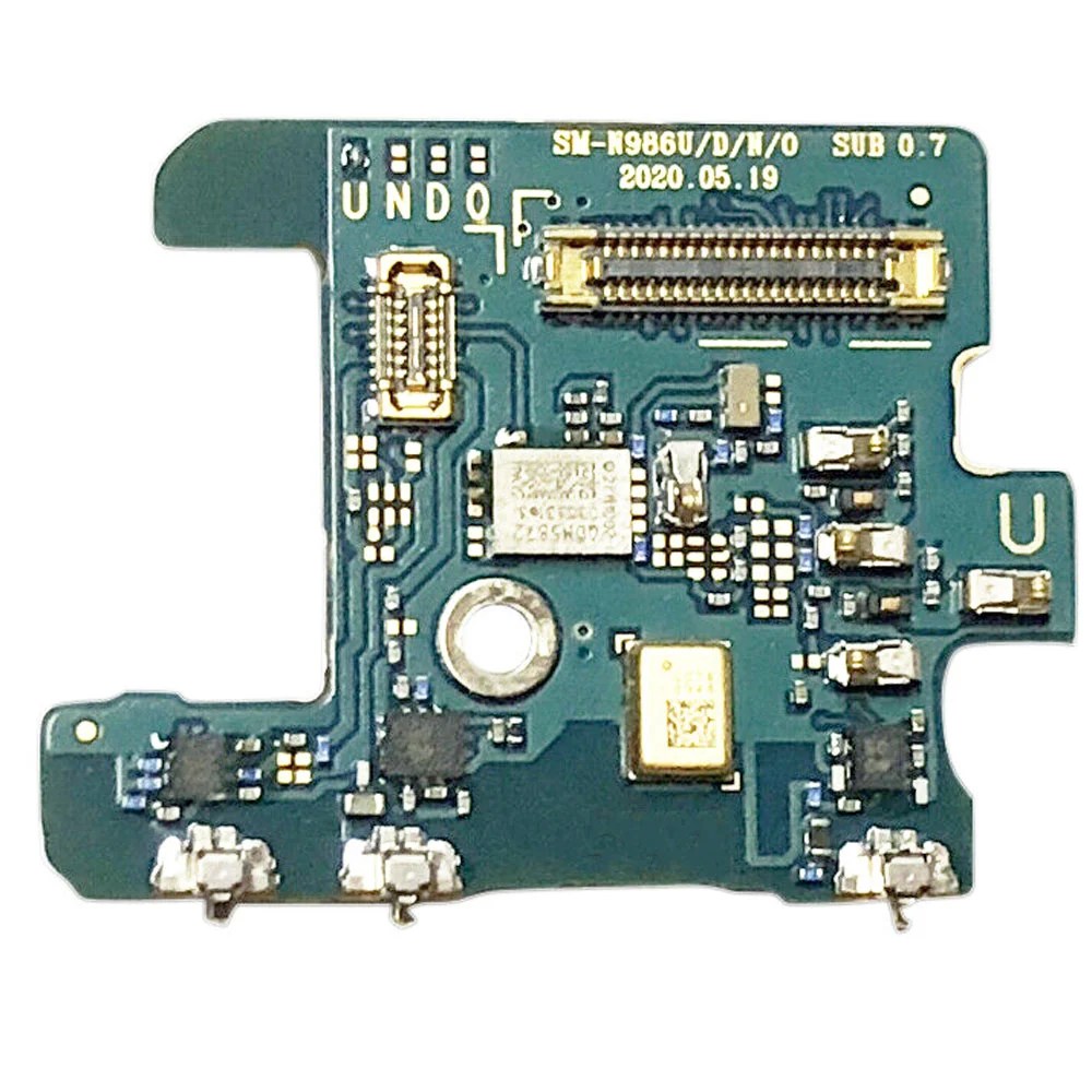
– Grab your trusty spudger (that pointy tool, you know the one!), and gently pry up the white connector tucked away in the bottom right corner of the motherboard shield. It’s like giving it a little high five to say goodbye!
Tools Used
Step 9

Hey, those screws might be a little stubborn if they’re brand new. They’ve got a special goop on them that helps them stay put.
It’s super important to remember where each screw goes! You can think of it like a puzzle, and each screw is a special piece. Put ’em back in their spots, and everything will be just fine.
– Grab your trusty Phillips screwdriver and unscrew those six 4.0 mm screws that are keeping the motherboard shield in place. Let’s get this party started!
Step 10


Heads up! The motherboard shield is a bit delicate. It’s got some sharp edges, so handle it with care. You got this!
– Grab your trusty tweezers and gently lift up that motherboard shield like a pro.
– Now, use your fingers to firmly but carefully grip the motherboard shield.
Tools Used

Step 11


Alright, so this wireless charging coil is stuck on there with some sticky stuff. It’s not a super strong bond, but it’s enough to keep it in place. Just take your time and be gentle, and you’ll be good to go! If you need help, you can always schedule a repair.
– Time to get that wireless charging coil outta there! Gently peel it up and away from the device. It’s like giving it a little hug goodbye.


Step 14

– Alright, let’s get this show on the road! Grab your trusty Phillips screwdriver and give those four 4.0 mm screws securing the earpiece speaker a little nudge. Don’t worry, we’re almost there! If you need help, you can always schedule a repair.
Step 15


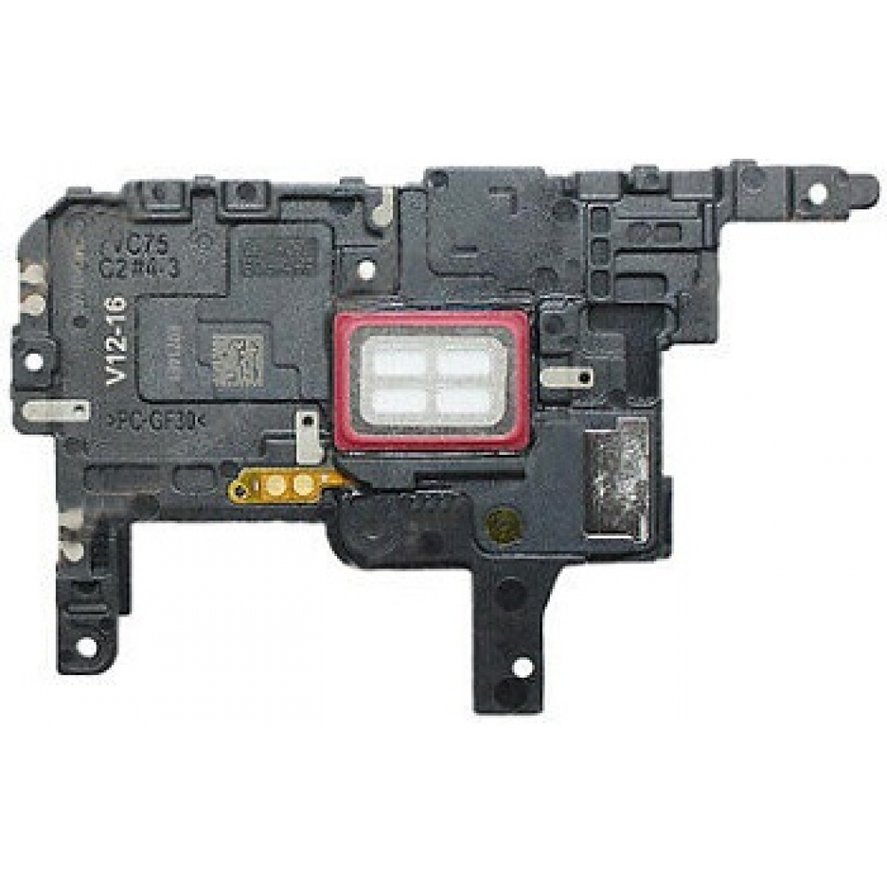
Hold on to your hat, this next part is a cinch! The earpiece speaker just clips to the frame at the top edge. It’s like a little party for your speaker, and the frame is the guest of honor. Just give it a little nudge and it’ll pop right off. If you need help, you can always schedule a repair
– Let’s get this earpiece speaker out! Find the little triangle mark on the right side of the earpiece speaker. Gently slide the pointed end of your trusty spudger into that hole.
– Now, using your spudger like a tiny lever, carefully pry up and loosen the earpiece speaker from the frame. You’re almost there! Remember, a gentle touch is key.
Tools Used


Step 17

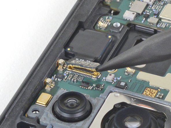
– Now, let’s gently disconnect the front-facing camera cable from the motherboard. Use the pointed end of your spudger to carefully lift the connector. You got this!
Tools Used
Step 18


– Now it’s time to disconnect the display cable from the motherboard. Use the pointed end of a spudger to gently pry it loose. If you’re not feeling confident, don’t worry – you can always schedule a repair and let the pros at Salvation Repair handle it for you.
Tools Used
Step 19
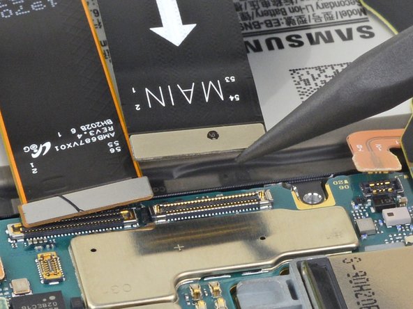

– Let’s get that main interconnect cable disconnected from the motherboard! Use the pointed end of your spudger to gently separate the connection. If you need help with any of this, you can always schedule a repair.
Tools Used
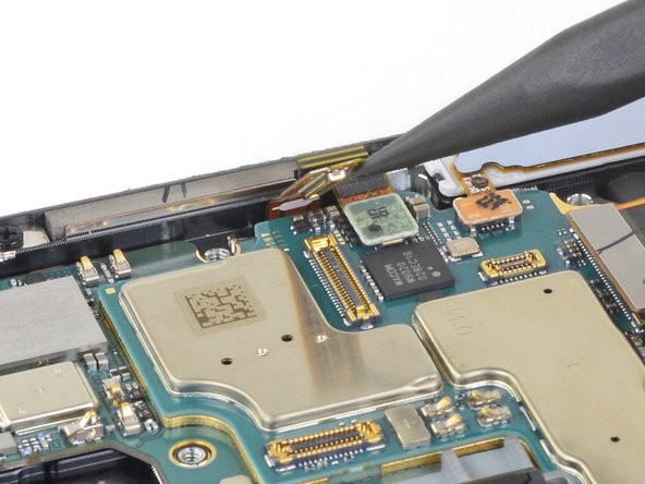
Step 20


– Now it’s time to carefully disconnect the secondary interconnect cable from the motherboard – use the pointed end of a spudger to get the job done. If you need help, you can always schedule a repair
Tools Used
Step 21


– Grab your trusty spudger and gently use its pointed end to unplug the touch layer cable from the motherboard. You’ve got this!
– Next up, take that same spudger and carefully disconnect the green press connector from the motherboard. Keep it going, you’re almost there!
Tools Used
Step 22
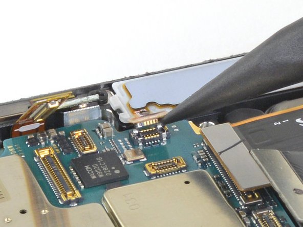

– Now it’s time to carefully disconnect the S-Pen press connector from the motherboard – simply use the pointed end of your trusty spudger to get the job done. If you need help, you can always schedule a repair
Tools Used
Step 23

– Let’s get started by using a Phillips screwdriver to remove the two 4.0 mm screws that hold the motherboard in place. Simply unscrew them from the frame and set them aside – you’re making great progress already. If you need help, you can always schedule a repair
Step 24

– Time to get this motherboard loose. Start by sliding the flat end of a spudger under the bottom edge – it’s the perfect tool for the job.
– Gently pry up to loosen the motherboard from the frame. Take your time, and it’ll come loose in no time. If you need help, you can always schedule a repair
Tools Used
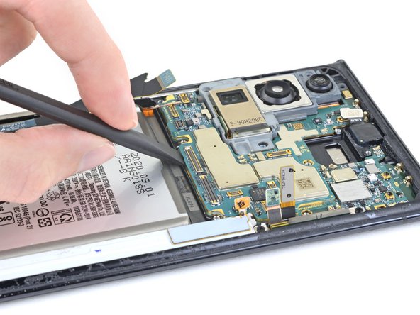
Step 25
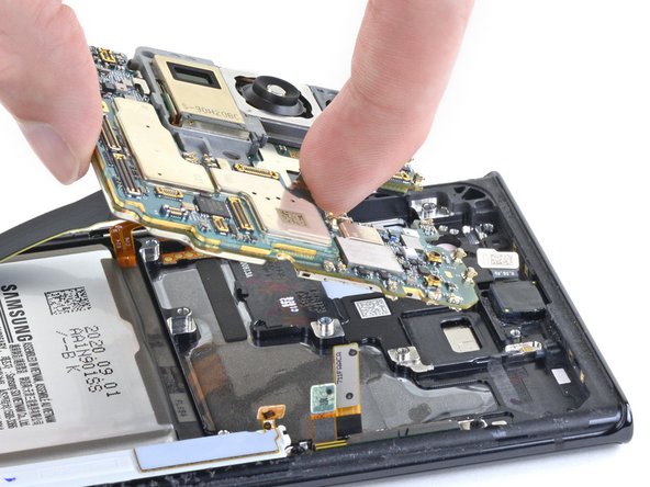

Don’t break any of those teeny tiny press connector buddies while ya pry out that motherboard hun! If ya need help, you can always check out schedule a repair
– Time to free the motherboard! Carefully lift it out of the phone. You’re doing great! If you need help, you can always schedule a repair
Step 26

– Alright, champ, time to drop that motherboard back in! Make sure you’re careful as you lower it down – you don’t want any cables getting caught under the board. Give these seven spots a good look-over to make sure everything’s clear:
– Secondary interconnect cable
– Battery cable
– Main interconnect cable
– Display cable
– S-Pen cable
– Touch layer cable and green press connector
– Front-facing camera cable
Step 27


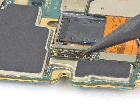
– Now, grab your spudger and use the pointy end to carefully disconnect the ultra-wide camera from the motherboard. Don’t worry, it’s just like unplugging a phone charger. If you need help, you can always schedule a repair.
Tools Used
Step 28

– Let’s get this camera disconnected! Gently use the pointed end of a spudger to separate the telephoto camera from the motherboard. Take your time, you got this!
Tools Used
Step 29


– Whoa there, let’s gently tap-tap with our spudger friend to disconnect the wide-angle camera from the motherboard. You’ve got this! No worries if you need a hand; give our peeps at schedule a repair a shout if you need some extra love.
Tools Used
Step 30

Watch the ribbon cable’s back, as bending it more than 90 degrees can put a damper on its dance moves!
– Give that ultra-wide camera ribbon cable a little bend, away from the motherboard. It’s just a little move to free up the rear camera assembly. Easy peasy, right? If you need help, you can always schedule a repair
Step 31

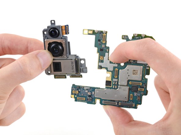

Hold up! The rear camera assembly is chilling right there on the motherboard, secured with a little bit of adhesive. You’ll find it to the right of the telephoto camera. Don’t worry, it’s not a big deal to remove. If you need help, you can always schedule a repair.
– Time to give that rear camera assembly the boot! Gently remove it from the motherboard. It’s like a mini-break for the camera, don’t worry, it’ll be back soon. 😉
– Alright, reassembly time! If you’re using a pre-cut adhesive card to secure the new rear camera assembly to the motherboard, follow these steps. It’s like a tiny hug for your new camera. If you need any help, you can always schedule a repair