Samsung Galaxy Note20 USB-C Port Replacement Guide
Duration: 45 minutes
Steps: 22 Steps
Before you start disassembling your phone, make sure to discharge the battery to below 25% for your safety. If you need help, you can always schedule a repair
Get ready to swap out the USB-C port on your Samsung Galaxy Note20! Before diving in, make sure to juice that battery down to below 25%. This little step helps keep things safe and sound, reducing the chance of any unexpected thermal surprises if the battery gets a bit too cozy during the repair. And hey, if your battery looks like it’s been hitting the gym a bit too hard, take the right precautions!
Step 1

First things first, let’s give your phone a little time out. Make sure it’s completely powered off before we start taking things apart.
A hairdryer, heat gun, or hot plate can be your new best friend for this step. But be careful! Don’t get carried away with the heat, as the screen, battery, and back cover are sensitive to the heat. We don’t want any accidental meltdowns, right?
– Grab your trusty iOpener, heat it up for a minute, and gently apply it to the left side of the rear cover. Let’s get this party started!
Tools Used

Step 2


Keep that opening pick to a cool 5 mm or less when diving into your phone—going deeper could mean a surprise encounter with the internal components!
If your phone is feeling a bit stubborn, don’t worry! Just give it a little extra warmth and try again. You’re doing great!
– Grab a suction cup and stick it to the warmed edge of the back cover, aiming for that sweet spot right near the edge.
– Gently but firmly pull up on the suction cup to create a little gap between the rear cover and the frame. You’ve got this!
– Slide an opening pick into that gap you’ve created.
Step 3


Be careful as you cut through the adhesive around the phone’s perimeter – don’t insert the pick more than 5 mm to avoid damaging the internal components. If you need help, you can always schedule a repair
– Gently glide the opening pick down the left edge, making your way toward the bottom left corner to slice through that stubborn adhesive.
– Keep the pick nestled in the bottom left corner to stop the adhesive from getting any funny ideas about re-sealing.
Step 4


If the rear cover is still stuck to the frame after you’ve sliced through all four sides, try slicing through the adhesive again with an opening pick.
You can insert each new opening pick in the gaps created by the opening picks left in each corner. If you need help, you can always schedule a repair
– Keep the good times rolling by heating and slicing through the adhesive on the last three sides of the rear cover. You’re almost there!
– As you work your magic, pop an opening pick in each corner to keep that adhesive from getting cozy again.
Step 5


– Gently lift the rear cover straight up to pop it off.
Step 6

Heads up! These screws might be a little stubborn, as they’ve got a bit of threadlocker holding them in place. Don’t worry, they’ll come loose with a little gentle persuasion.
Remember to keep track of all those screws, like a puzzle piece, they need to go back where they came from!
– Grab your trusty Phillips screwdriver and get ready to tackle those six 4.0 mm screws holding your motherboard shield in place. Let’s do this!
Step 7


Handle the motherboard shield with care—its edges are as sharp as your wit!
– Time to get up close and personal with the motherboard – use a trusty pair of tweezers to carefully lift and flip back the shield, and you’ll be one step closer to getting your device back in action. If you need help, you can always schedule a repair
Tools Used

Step 8


Be careful when prying under the edge of the connector – you want to avoid damaging the socket or surrounding parts. If you’re not feeling confident, don’t worry, you can always schedule a repair
– Hold the motherboard shield steady with your trusty tweezers while you gently pry up the battery press connector using the pointed end of a spudger. It’s like giving it a little nudge to say ‘hello’!
– To reconnect these connectors, carefully line them up and press down on one side until it clicks into place. Then, repeat on the other side. Don’t push down in the middle, it’s like a delicate dance! If you accidentally misalign it, the pins might get a little bent. Don’t worry, if you’re ever unsure, you can always schedule a repair with us.

Step 9


– Hold the motherboard shield out of the way with your trusty tweezers, and then use the pointed end of a spudger to gently lift up the wireless charging coil press connector. You’re almost there! If you need help, you can always schedule a repair
Step 10


The wireless charging coil is gently held in place with a bit of light adhesive magic.
– Give that motherboard shield a gentle grip with your fingers.
– Carefully lift the wireless charging coil up and away from the device with a steady hand.
– Time to set the wireless charging coil free! Remove it from the device.
Step 11

– Alright, time to unleash that speaker! Grab your trusty Phillips screwdriver and give those five 4.0mm screws securing the loudspeaker a little twist. You’ve got this!
Step 12


Step 13


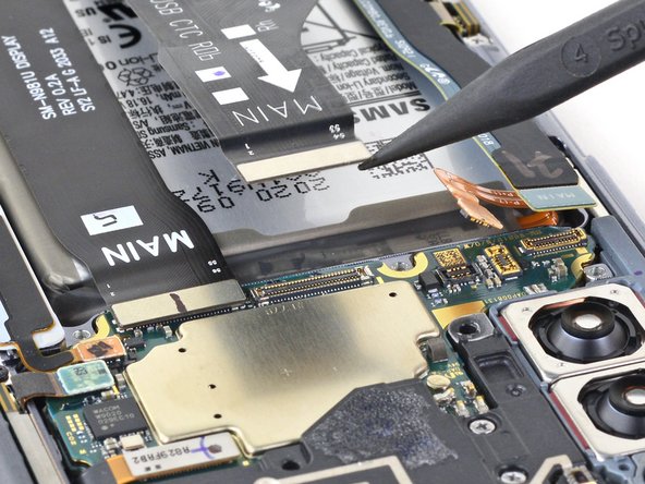
– Now it’s time to get connected – or rather, disconnected. Use the pointed end of a spudger to carefully release the main interconnect cable from the daughterboard. If you need help, you can always schedule a repair
Tools Used


Step 15


– Grab your trusty spudger and gently use its pointed end to unplug the secondary interconnect cable from the motherboard. You’ve got this!
Tools Used
Step 16

– Grab your trusty spudger and gently pop that main interconnect cable off the motherboard. It’s like giving the cable a little high five, but with a tool!
Tools Used
Step 17

– Grab your trusty Phillips screwdriver and carefully unscrew that 2.9 mm screw holding the daughterboard snug against the frame. You’ve got this!
Step 18


Be careful, there are tiny components hanging out beneath the daughterboard! Just slide that spudger in gently—only as much as you need to—so we don’t accidentally give those little guys a rough day.
The daughterboard is secured to the frame with three handy spring connectors along its lower edge.
– Gently slide the pointed end of a spudger under the right side of the daughterboard, right near that little screw boss. You got this!
– Now, use that spudger to carefully pry up and separate the daughterboard from the frame. Easy peasy!
Tools Used
Step 19


– Time to get a little delicate – use a pair of tweezers to carefully lift and remove the daughterboard. If you need help, you can always schedule a repair
Tools Used
Step 20

– Grab your trusty Phillips screwdriver and tackle those two 2.9 mm screws that are holding the USB-C port in place on your phone. Let’s get that port out and ready for action!
Step 21

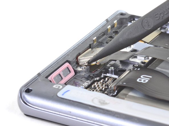
Be careful when prying the USB-C port – it might pop out of its slot unexpectedly, so take your time and be gentle.
So here’s the deal, you’ve got yourself a colorful red rubber gasket that’s holding down the USB-C port. It’s like a little champion keeping it in place! But don’t sweat, because you’ve got this! Give it a nice, steady tug and watch as it starts to loosen from its cozy little slot. You rock!
– Time to get started – carefully insert the pointed end of a spudger under the right side screw hole on the USB-C port.
– Gently pry up the USB-C port to loosen it from the frame. If you need help, you can always schedule a repair
Tools Used
Step 22

Keep that ribbon cable nice and straight! Bending it too much can lead to some serious damage, and we definitely want to avoid that. You’ve got this!
– Alright, grab that USB-C cable and get a grip! Hold it nice and close to the USB-C port.
– Now, it’s time to give that USB-C port a little farewell hug. Gently pull it up and away from the bottom of your phone, and let it go free.