Samsung Galaxy Note9 Front Sensor Array Replacement Guide
Duration: 45 minutes
Steps: 32 Steps
Get ready to breathe new life into your Samsung Galaxy Note9 by replacing the front sensor array. Our step-by-step guide will walk you through the process. If you need help, you can always schedule a repair.
Step 1


– Grab your handy SIM card eject tool and slide it straight into the tiny hole of the SIM card tray.
– Give it a little push and watch the SIM card tray pop right out!
Tools Used

Step 2

The SIM card should just slide right out of the tray. No drama, no fuss!
– Let’s pop that SIM card tray out. No worries, it’s easy!
Step 3

– First things first, turn off your phone before diving into the disassembly adventure!
– Next, grab your trusty hairdryer, heat gun, or an iOpener and apply it to the right edge of the back of your phone for approximately a minute. This will help soften that stubborn adhesive hiding underneath.
Tools Used

Step 4


Don’t worry, if that sticky stuff is giving you a hard time, just add a little more heat – no need to be a Hulk about it! Too much force and you might end up with a cracked screen, and no one wants that. 😉
If your glass is sporting some serious cracks, simply slap on some packing tape! This will give the suction cup something to grip onto, making your repair journey a little smoother.
– First, attach a suction handle to the back cover – it’s time to get this repair started!
– Now, use that suction handle to carefully lift the back cover and create a gap between it and the phone’s frame.
– Next, take an opening pick and gently insert it into the gap you just created. You’re making great progress! If you need help, you can always schedule a repair
Tools Used

Step 5

If the adhesive is putting up a fight, just give it some extra heat instead of extra muscle.
– Hey, there’s more sticky stuff up top and around the camera, so be careful there.
– Around the left side, near the fingerprint sensor, cut with care—you don’t want to mess with the ribbon cable hiding inside!
Step 6


Hey there, just a quick tip! When you’re using the pick to cut near the fingerprint sensor or cameras, don’t go too deep. Keep it halfway in or less to keep everything inside happy and healthy. If you’re feeling unsure, you can always schedule a repair and let our pros handle it.
– Alright, let’s get this party started! Starting from the center, carefully cut the adhesive up and down the right side using an opening pick. Don’t worry, you’ve got this! If you need help, you can always schedule a repair
Step 7


Heads up! This corner is kinda delicate, so be gentle. If the adhesive gets sticky, just add a little more heat. You got this!
– Let’s get this party started! Wedge an opening pick into the upper-right corner.
– Now, use another opening pick to slice through the adhesive around the bottom-right corner.
– Keep that opening pick in place while you move on to the next step. You got this!
Step 8

– Let’s get that adhesive nice and loose! Use a heat gun, hair dryer, or a heated iOpener to warm up the left side of the rear panel for about three minutes. This will help soften the adhesive underneath, making it easier to remove the panel. If you’re feeling stuck, you can always schedule a repair.
Tools Used
Step 9


Watch out for those corners, the glass is a little delicate there.
Don’t push that opening pick too far on the left edge near the fingerprint sensor, or you might hurt the ribbon cable inside. If you need help, you can always schedule a repair.
Don’t worry if your opening picks fall out as you separate the back cover – it’s all part of the process. If you need help, you can always schedule a repair
– Slide an opening pick into the lower-left corner of the back panel with a gentle touch.
– Grab another opening pick and carefully slice through the adhesive along the left side of the back panel.
Step 10


Apply some extra heat with an iOpener, hair dryer, or heat gun where you’re cutting through the adhesive – it’ll make the process a whole lot easier. If you need help, you can always schedule a repair
– Alright, let’s keep going. With your trusty opening pick, gently cut the adhesive surrounding the upper-left corner of the back panel. You’re almost there!
– You got this! Now, make the final cut along the top of the phone. See, you’re a pro at this!
Tools Used
Step 11


Hold your horses! Don’t touch the fingerprint sensor ribbon cable just yet. We’ll get to it later.
The fingerprint sensor cover might just want to stick around with the midframe.
– Start by gently separating the right side of the rear cover.
– Then, tilt the cover up along the left edge to reveal the fingerprint sensor ribbon cable. You’re doing great!
Step 12


– Time to get that fingerprint sensor ribbon cable out of its socket. Use the tip of a spudger to carefully pry it up and out – you’re making great progress. If you need help, you can always schedule a repair
Tools Used

Step 13

– First up, let’s get that back cover off! It’s time to unveil the magic inside.
– Now, when you’re ready to put the back cover back on, here’s how to do it right: Use tweezers to gently remove any leftover adhesive from the phone’s chassis. Give those adhesive spots a good clean with some high concentration isopropyl alcohol (at least 90%) and a lint-free cloth to make sure everything’s prepped for the new adhesive. No need to go crazy cleaning down to the plastic—just get rid of the bigger bits.
– Once that’s done, power up your phone and give your repair a quick test before slapping on the new adhesive and sealing it back up.
– Finally, apply the new adhesive to the back cover with care. Align one edge of the glass with the phone chassis and press it down firmly. You’ve got this!
Tools Used

Step 14


– Let’s get started by removing the nine 4mm screws that hold the upper midframe in place – grab your trusty Phillips screwdriver and get to work! If you need help, you can always schedule a repair
Step 15


The upper midframe clicks in and out with a satisfying snap!
– Let’s get this upper midframe outta here! Carefully slip the tip of your trusty spudger into the top-left corner of that upper midframe.
– Now, gently pry that midframe away from the phone. Take your time and be a pro!
Tools Used
Step 16


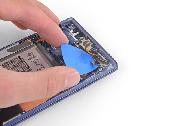
The adhesive might be feeling a bit lazy, but no worries! Grab an opening pick and slice right through it if you need to.
– Gently unstick the wireless charging coil from the battery, starting from the left side. Take your time, it’s like a gentle peel away from the sticky side of life!
– When putting it all back together, remember to click the midframe into position first before pressing down the wireless charging coil. It’s like setting the stage for a performance!
Step 17


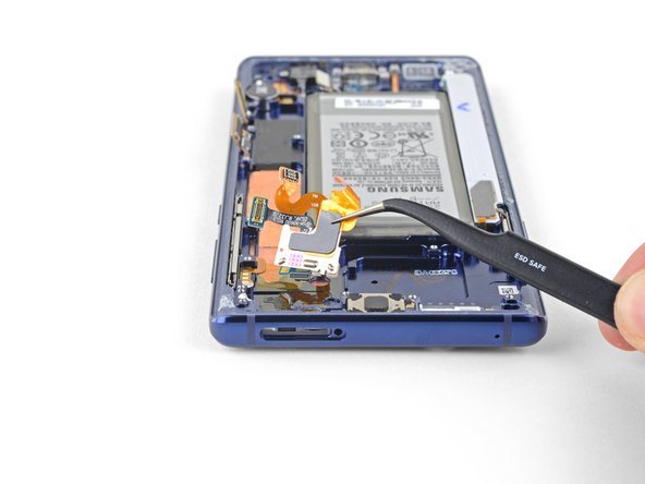
– Time to give that orange ribbon cable a little break! Gently use the tip of a spudger to disconnect it from the motherboard. You’re almost there! If you need help, you can always schedule a repair.
Tools Used
Step 18

– Let’s tackle this together! Start by removing the nine 4 mm Phillips screws from the plastic cover near the battery. You’ve got this!
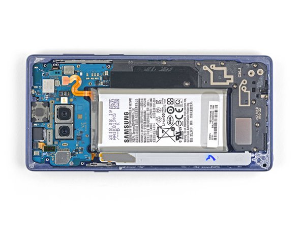
Step 19

– Let’s get started by removing the plastic cover located next to the battery. If you need help, you can always schedule a repair
Step 20


You’ve got this! Watch as the lower midframe snaps smoothly into place, like a little puzzle piece. Keep up the great work!
– Slide the tip of a spudger into the top of the lower midframe.
– Gently pry the lower midframe away from the phone. It’s like giving it a little hug to say goodbye!
– Remove the lower midframe. You’re doing great! If you need help, you can always schedule a repair
Tools Used
Step 21


– Grab that trusty spudger and gently nudge the front camera connector straight up and out of its cozy little socket.
– Now, let those tweezers do the magic and carefully lift out the front camera.
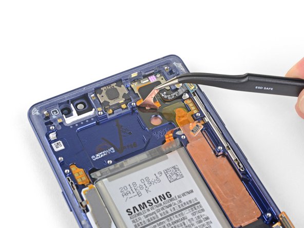
Step 22


– Grab your trusty spudger and gently pry away the iris scanner from the motherboard. You’ve got this!
– Next, take your tweezers and delicately lift out the iris scanner. Easy peasy!
Step 23


– Time to get that front sensor connector out – use the flat end of your trusty spudger to gently pry it out of its socket. If you need help, you can always schedule a repair
Tools Used
Step 24


– Grab your trusty spudger and gently use its flat end to disconnect the display cable from the motherboard. You’re doing great!
Tools Used
Step 25


– Now it’s time to disconnect the touchscreen cable from the motherboard. Use the flat end of a spudger to gently pry it loose – you got this! If you need help, you can always schedule a repair
Tools Used
Step 26


– Now, let’s gently disconnect that charging assembly from the motherboard. Grab your trusty spudger (the flat end, of course) and carefully pry it apart. No need to get too forceful, just a little persuasion is all it takes. If you’re feeling a little unsure, you can always schedule a repair.
Tools Used
Step 27


– Let’s get started by removing the three 4mm Phillips screws that hold the motherboard in place.
– Take a look for the triangles next to the holes – they’ll give you a hint about where the screws go. If you need help, you can always schedule a repair
Step 28


Gently nudge those ribbon cables out of the way when needed. If the motherboard gets stuck on any cables, just take a breath and don’t yank it out.
– Let’s get that motherboard out! Use a spudger to gently lift the motherboard from the upper-left corner.
– Now, carefully remove the motherboard. No worries, it’s like a puzzle piece! If you need help, you can always schedule a repair
Tools Used

Step 30

Be careful not to remove the front sensor array just yet, as it’s still connected to a ribbon cable stuck to the phone. Let’s take it one step at a time to avoid any damage. If you need help, you can always schedule a repair
– Now it’s time to carefully pry the left side of the front sensor array loose. Use the tip of a spudger to gently lift it up and break the remaining adhesive bond. If you need help, you can always schedule a repair
Tools Used
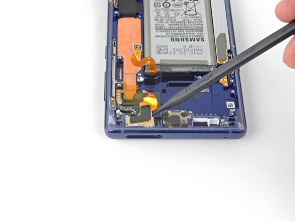
Step 31

– Gently slide an opening pick under the front sensor array ribbon cable to slice through the adhesive below.
Step 32

– Time to get up close and personal with your device’s front sensor array – use a trusty pair of tweezers to carefully remove it. If you need help, you can always schedule a repair
Tools Used