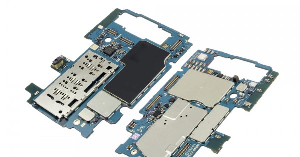
Samsung Galaxy On5 Display Assembly Replacement Guide
Duration: 45 minutes
Steps: 20 Steps
This device features a vibrant 5-inch display with a crisp resolution of 720×1280 pixels. Plus, it’s a touchscreen, so you can tap, swipe, and scroll with ease! If you need help, you can always schedule a repair.
Step 1

– Find the side notch – it’s the key to unlocking the back casing.
Step 2


– Grab a plastic prying tool or even your trusty fingernail and gently nudge the back cover off your phone. You’ve got this!
Step 3


Hey, be careful not to poke the battery. It’s like a little firecracker waiting to go boom if it gets exposed to too much air!
– Let’s get started by locating the battery notch. You can use your finger or a plastic prying tool to carefully remove the battery. If you need help, you can always schedule a repair
Step 4

Hey, don’t use a metal pry tool – that’s like trying to open a can of soda with a butter knife! You could damage the cards or their holder, and nobody wants that. If you need help, you can always schedule a repair.
– Before diving into your phone’s insides, don’t forget to remove the SIM card and microSD card. Trust us, they’ll thank you!
– Grab a plastic pry tool and gently slide both cards out – it’s a piece of cake!
Step 5


Opening this part might require a bit of finesse. Take your time, and remember to be gentle—too much pressure could lead to some ribbon damage. You’ve got this!
– Let’s pop that LCD ribbon cable cover open! Use your handy-dandy plastic Spudger tool to gently pry it open. It’s like giving it a little high-five, but with a tool. If you need help, you can always schedule a repair.
Tools Used

Step 6
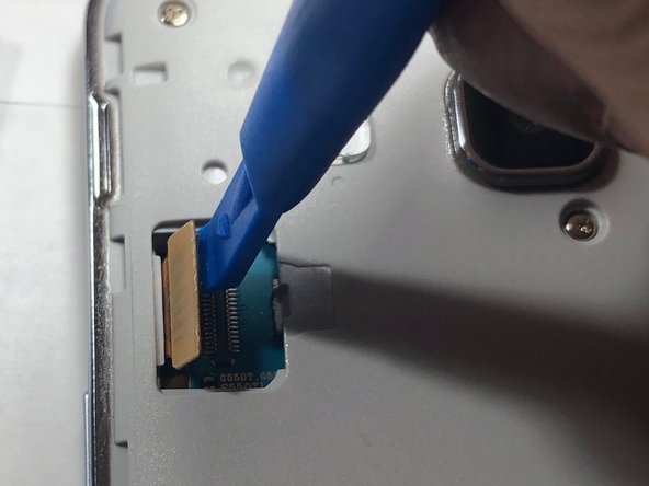

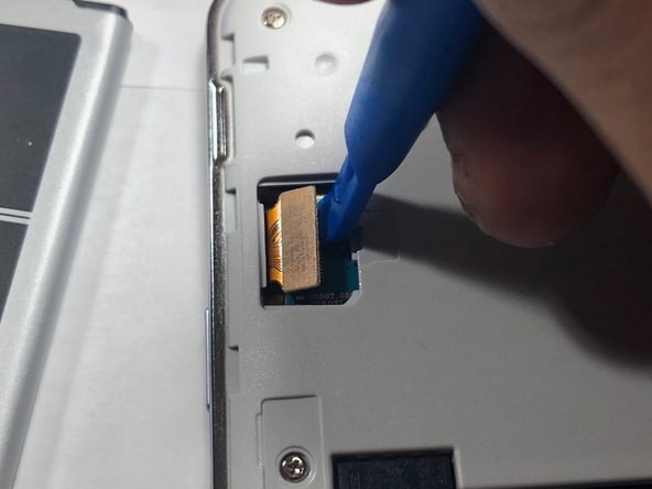
Hey, be careful! Avoid using metal pry tools. These tools can accidentally damage the logic board and ribbon cable. If you need help, you can always schedule a repair.
This little ribbon cable is the messenger between your phone’s brain (the logic board) and the screen. It’s the one that makes sure what you see on your screen is actually what’s happening! So, be careful with this one, okay?
– Now, for a little bit of delicate work, use your trusty plastic pry tool to gently nudge that LCD ribbon cable off the logic board. Take your time – we’re not in a hurry, and we want to make sure everything stays happy and healthy.
Step 7


No need to worry about remembering which screw goes where – all 9 are the same size. Easy peasy!
– Grab your trusty Phillips #00 head and carefully remove all 9 screws. Set them aside in a safe spot where they won’t get lost. If you need help, you can always schedule a repair
Step 8


This process might be time-consuming, but no worries! Just take your time as you carefully work around the edge of the screen to loosen up that pesky glue holding theLCD and back assembly together. If you’ve got a heat gun handy, it’s like giving that glue a warm hug, making it easier to separate the pieces. You’ve got this!
– Grab your trusty iFixit plastic pick and gently coax that LCD away from the back assembly. It’s like a little dance, just be smooth about it. If you need help, you can always schedule a repair
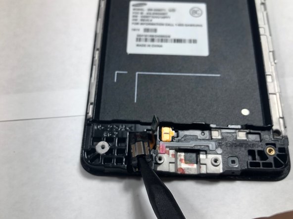
Step 9
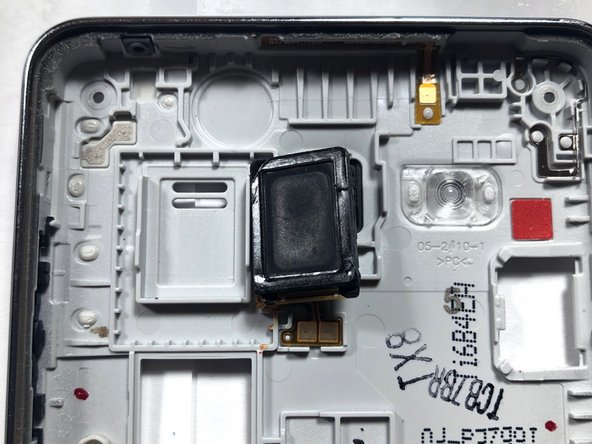

– Once you’ve successfully separated the LCD from the back assembly, take a peek at the back assembly where the speaker hangs out.
– When you’ve found it, grab your trusty plastic pry tool to carefully lift out the speaker from its cozy home and swap it with a shiny new one.
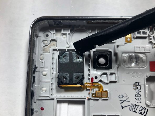
Step 10

Always choose a plastic pry tool instead of metal ones when you’re tinkering with those delicate gadgets. Your electronics will thank you for it!
– Time to give that front-facing camera a little lift! Gently pry it out of its cozy home using a plastic tool.
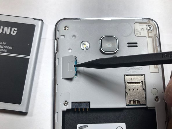
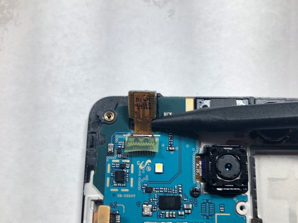
Step 11

– Pop that camera out of the housing and unplug it from the logic board. If you need help, you can always schedule a repair.
Step 12

– You’ve successfully removed the front-facing camera – nice work! If you need help with the next steps, you can always schedule a repair
Step 13

When you’re using a metal tool, keep your eyes peeled on where you’re putting that bit! Mishaps on the motherboard can be a real headache, and we want to avoid that at all costs.
– Let’s get started by removing the screw that holds the rear-facing camera in place. Grab your trusty Phillips #00 screwdriver and carefully take out the screw. If you need help, you can always schedule a repair
Step 14
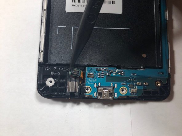

– Grab your trusty plastic pry tool and give that headphone ribbon a little nudge to disconnect it from the motherboard. It’s like saying ‘bye bye’ to the headphone jack!
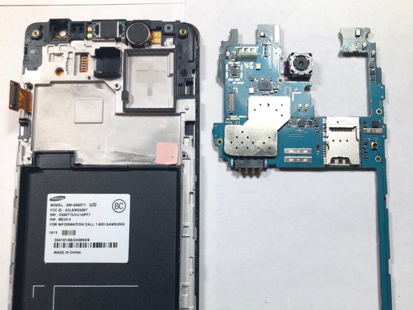
– Now, let’s lift up the motherboard from the LCD housing by grabbing the ends of the logic board. Think of it like giving your motherboard a little hug and a lift.
Step 15
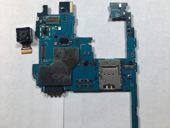

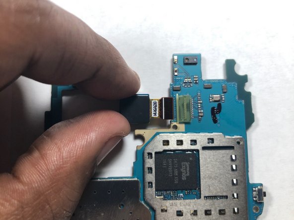
– Flip the logic board over so the camera lens is facing down, like it’s shy or something.
– Now, gently use your finger to pop the camera off its connection on the logic board. It’s like giving it a little high five, but without the high five.
Step 16

– Now that you’ve removed the cameras from the logic board, it’s time to swap it out with a new one. If you need help, you can always schedule a repair
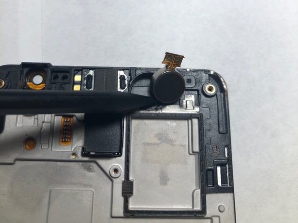
Step 17

– Use a plastic stick to carefully pry open the headphone jack and lift the housing – it’s easier than you think.
– Once you’ve got it open, set the part aside and get ready for the next step. If you need help, you can always schedule a repair
Step 18

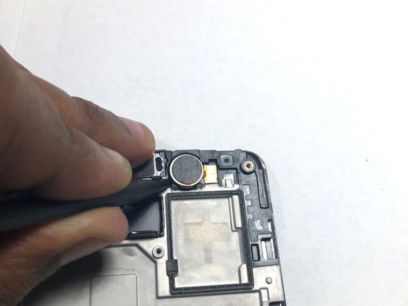
Don’t be shy about giving it a little extra push! The part is glued in, but it’s gonna come loose with a bit of friendly force.
– Now, grab that trusty tool again and gently pop the phone’s vibrator out of its cozy little home.
Step 19

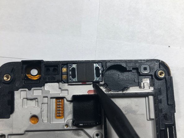
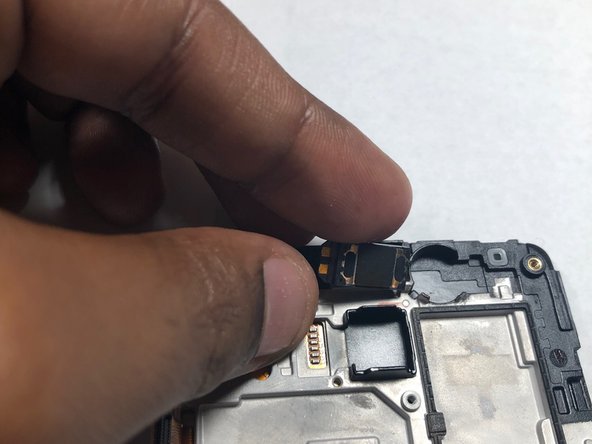
– Now, let’s get that earpiece out! Use a plastic pry tool to gently remove it from its housing. You got this!
Step 20

– Now that you’ve successfully removed all three parts, it’s time to cozy them up on the new LCD screen!