Samsung Galaxy S Motherboard Replacement Tutorial DIY Guide Step-by-Step
Duration: 45 minutes
Steps: 33 Steps
Hey there! Just a friendly reminder to take your time and double-check everything as you go. If you hit a snag or need a hand, don’t hesitate to schedule a repair. You’ve got this!
Follow this guide to swap out the old motherboard with a new one. It’s like giving your gadget a brand new brain!
Step 1


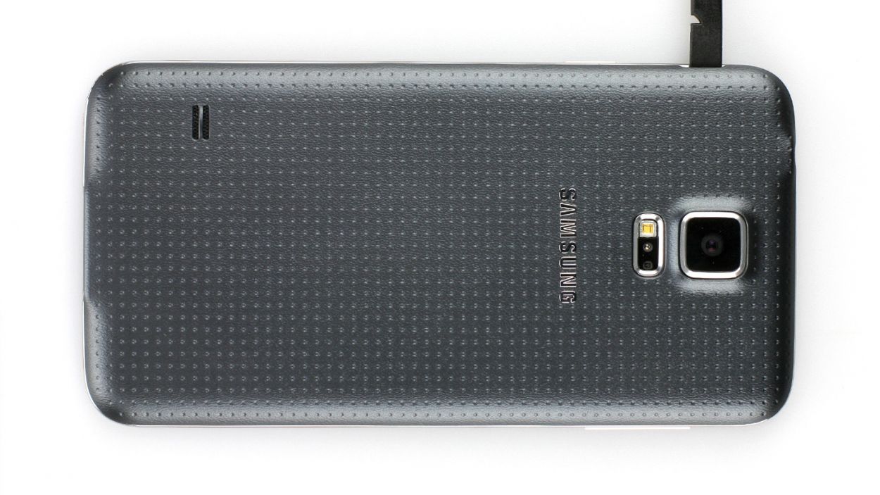
– Slide a fingernail or a trusty plastic opening tool into the little notch to the left of the rear-facing camera.
– Carefully ease and twist that flexible rear cover off the back of your phone like you’re peeling a banana.


Step 3


– Give your microSD card a gentle tug downwards to free it from its snug little home.
– Wave goodbye as you remove the microSD card from its phone habitat.
Step 4

– Let’s do that one more time! Follow the steps you just rocked at to remove the SIM card.
Step 5


– Grab a plastic opening tool and gently pry open the plastic midframe connector panel.
– Snag the connector panel using a pair of tweezers.
– The existing adhesive should do the trick for sticking it back together during reassembly. If not, a smidge of double-stick tape will save the day.
Step 6


– Grab your trusty spudger and use its sharp end to pop the home button cable connector right off its cozy socket. Like a boss!
Tools Used

Step 7


– Snuggle up a warmed-up iOpener on the left side of your phone for a cozy 90 seconds.
– Give your iOpener a quick pep talk and warm it up again, then let it hang out on the right side of your phone.
Tools Used

Step 8


In the following steps, you’ll be using an opening pick to gently detach the adhesive holding the front panel glass in place. Make sure to pry only where instructed. If you feel any resistance, take a moment to stop using the pick and warm it up again. We’ve got this!
– Slide the tip of an opening pick under the bottom right corner of the front glass, and let’s get this show on the road!
Step 9


– Glide the opening pick up the right side of the display like you’re spreading peanut butter on a slice of bread.
Step 10


– Gently wiggle the pick around the corner, but pause your groove before you hit the speaker grille at the top of the phone.
Step 11


The adhesive holding the top of your phone is just a slim strip right above the earpiece speaker. Gently slide your pick along the top of the speaker to keep those delicate internal components safe and sound.
– Glide the opening pick across the top edge of your phone like a mini surfboard. Just be super careful not to jam it in too deep. Keep it light and breezy!


Step 13


– Now it’s time to get this repair started – slide that opening pick down along the left half of your phone, stopping when you reach the lower left corner. If you need help, you can always schedule a repair
Step 14


Next up, you’ll be cozying up an iOpener on the home button side of your phone. Make sure your opening pick doesn’t go rogue and slip out!
– Whoosh your opening pick all the way down to the snazzy bottom left corner of your phone. Make sure it’s snug as a bug!
Tools Used
Step 15

This part of the phone has some super sensitive bits, so make sure the adhesive is nice and toasty to peel off easily—gotta keep your device happy and safe!
– Pop that iOpener into the microwave until it’s toasty warm, then lay it over the bottom part of the display assembly like you’re tucking it in for a nap.
Tools Used
Step 16


Heads up, tech whiz! The bottom of the phone is home to the soft button and home button ribbon cables. Dive too deep with the opening pick, and you might snip those vital connections. Let’s keep the surgery clean and precise!
– Whoosh that opening pick across the bottom edge of the display to wave goodbye to the last bits of adhesive hanging on for dear life.
Step 17


If the front panel is giving you a hard time and doesn’t want to come off, it might be time to show it who’s boss with a little more adhesive cutting magic.
– Give that opening pick a groovy twist to pop the glass off the phone like a pro.
Step 18


These cables are super slim and can tear faster than a sheet of paper! Make sure you’re just detaching them from the display assembly—no slicing and dicing!
If the front panel is feeling a bit stubborn, it might be time to give that soft button cable’s adhesive a little nudge to separate. No worries, you’ve got this!
– Slide your opening pick beneath those funky button icons on the display and gently wiggle those button cables free from the front panel’s embrace.
Step 19


Hold up! Don’t pull off the front panel completely—it’s still connected by a connector.
Reusing the home button flex cable? Handle with care! If it’s stuck, it could tear from the home button due to the adhesive. The button will work, but say goodbye to fingerprint scanning.
– Carefully lift, but don’t remove completely, the home button end of the display assembly. It’s just a little peek-a-boo!
Step 20
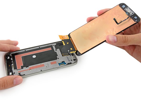


– Grab your spudger and use its sharp end to gently lift the front panel assembly cable connector straight up from its socket on the motherboard. Like a pro!
– Carefully separate the front panel assembly from the phone. It’s a smooth move!
– If your new display is missing a home button, no worries! Either follow our awesome Home Button Assembly guide to move your old button to the new display or pop in a new one. Keep rocking it!
Tools Used
Step 21

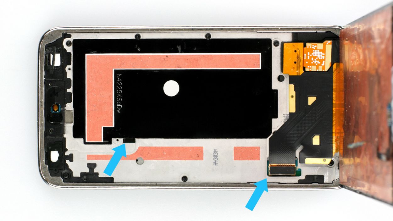
– Let’s get those ten 3.4 mm Phillips #000 screws off the display side of the midframe! You’ve got this!

Step 23


– Carefully slide a plastic opening tool along the left inner edge of the interior frame to pop free those three cheeky white plastic clips.
Step 24


– Carefully tug on the long sides of the silver bezel, pulling it away from the phone, to split the midframe into two cool halves.
You might want to nudge from the inside of the battery compartment—just a tad, though! Remember, no Hulk-smashing the interior half of the midframe; it’s home to the motherboard, and we want to keep the brain of your device happy and intact.
The midframe is like a cozy sandwich for the motherboard, made up of two halves that snugly hug it from both sides.
Step 25


– Move over to the right side of the shiny bezel and gently pull it away from the midframe’s interior to separate the two halves. You’ve got this!
Step 26


– Grab your trusty plastic opening tool and gently persuade those stubborn corners to leave the cozy confines of the silver bezel.
Step 27


– Gently coax the interior midframe/motherboard assembly away from the white inner midframe.
Step 28


Some models come with a duo of antenna cables (one blue and the other in grey/white). Go ahead and disconnect both of them.
– Gently slide the tip of a spudger under the antenna cable connector like a pro.
– Carefully lift the spudger straight up to pop that antenna connector off its cozy spot on the motherboard.
Tools Used
Step 29

– Take out the lone 3.0 mm Phillips #000 screw that’s holding the motherboard snugly against the midframe. You’ve got this!
Step 30


Hold up! Don’t try to yank out the motherboard just yet—it’s still connected to the midframe by the sneaky little Micro-USB port daughterboard connector.
– Gently hoist the camera end of the motherboard just a bit from the midframe—it’s like peeking behind a curtain! This move lets you get to those sneaky connectors hiding at the back.
Step 31


– Grab a spudger and carefully lift the daughterboard connector straight up from its socket on the motherboard. Need a hand? schedule a repair.
Tools Used
Step 32


– Grab your trusty spudger and gently pry off the front-facing camera connector from its cozy spot on the motherboard.
– Now, carefully lift the front-facing camera away from the motherboard and set it aside.
Tools Used
Step 33

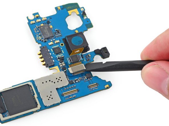

– Grab a spudger and pop the rear-facing camera connector straight up from its socket on the motherboard.
– Lift the rear-facing camera away from the motherboard.
Tools Used