Samsung Galaxy S20+ Earpiece Speaker Replacement Guide
Duration: 45 minutes
Steps: 39 Steps
Hey there, tech wizard! It looks like this step might require a bit of extra finesse. Don’t fret though, you’ve got this! If you need a hand, you can always schedule a repair with our team of experts. Keep up the great work!
Ready to tackle your Galaxy S20 Plus? Let’s get that earpiece speaker out and shining! While you technically could leave the motherboard in place, trust us: you’ll have a much smoother time getting to that sneaky little speaker if you take it out first. Just think of it as clearing the path for an easier repair adventure!
Step 1


– Get ready to perform a little magic trick! Take your trusty SIM card eject tool, bit, or even a straightened paperclip and make your way to the top edge of your phone next to the oh-so-stylish plastic antenna band.
– With confidence, give that tray a little nudge and watch it gracefully pop out. Stay fabulous!
Tools Used

Step 2


– Hey there! Let’s kick things off by removing the SIM card tray.
– When it’s time to pop the SIM card back in, make sure it’s facing the right way in relation to the tray.
– Keep an eye out for a nifty little rubber gasket encircling the SIM tray. This baby is your phone’s shield against water and dust. If this champ is damaged or taking a day off, swap it out pronto. Your phone’s vital organs will thank you!
Step 3

Make sure to unplug and power down your phone before diving in!
– Warm up the iOpener and gently apply it to the lower edge of the back cover for a couple of minutes.
Tools Used

Step 4


– Place a suction cup on the back of your phone, aiming for the center of the bottom edge—let’s get a good grip!
– Give that suction cup a nice, strong pull to open up a little gap between the back cover and the frame. You’ve got this!
– Now, gently slide the tip of an opening pick into that gap you just created. Let’s keep moving!
Step 5


– Alrighty, it’s time to get your slide on, rock that pick along the bottom edge – let’s slice this adhesive like a boss! Now, don’t forget to give your opening pick a partner for that juicy seam – we don’t want anything coming back together now, do we?
Step 6

– Alrighty! Warm up the magic heater on the left side of the back cover for about two mins. You’ve got this!
Tools Used
Step 7


Because of those snug fits, you might need to give it a few tries. No worries, you got this!
– Grab a suction cup and place it on the back of your phone, aiming for the center near the left edge—you’re doing great already!
– Now, give that suction cup a good steady pull. This will help you create a little gap between the back cover and the frame; it’s like opening a mini treasure chest!
– Once you see that gap, take the point of your opening pick and gently slide it in there. You’ve got this!
Step 8


– Once your trusty pick is nestled under the edge of the glass, give it a little tilt downwards and slide it in a bit more to completely break free from that sticky back cover adhesive.
Step 9


– Gently glide your pick down the left side of the phone to break apart that stubborn adhesive on the back cover.
– Keep your pick snugly in place under the left edge of the glass to stop that adhesive from making a comeback!
Step 10

– Warm up that trusty iOpener and give the right edge of the back cover a cozy two-minute hug.
Tools Used
Step 11


– Grab a trusty suction cup and place it lovingly on the back of your device, aiming for the center of the right edge.
– Channel your inner superhero and pull on that suction cup with a firm and steady hand. Your goal? Create a sweet little gap between the back cover and the frame.
– Take your opening pick and gently wiggle it into that gap like a key fitting into a lock. You got this!
Step 12


– Gently slide the pick all along the right edge of the phone to separate the back cover’s adhesive.
– Don’t forget to leave your pick snug under the right edge of the glass near the top of the device to make sure that adhesive doesn’t reseal on you.
Step 13

– Give that back cover a warm welcome by applying a heated iOpener to the top edge for a cozy two minutes.
Tools Used
Step 14


The glass around the corners of the back cover has a bit of a curve and can be a little fragile. So, take it easy during this step to keep your back cover safe and sound!
– Hey there! Let’s kick things off by smoothly sliding the pick from the right edge of the device all the way around to the top right corner.
– You’re doing great! Keep slicing along the top edge, making your way around to the left edge with style to completely separate the back cover adhesive.
Step 15


– Gently lift off the back cover, taking your time! Use those nifty opening picks to slice through any stubborn adhesive left behind.
– Carefully remove the back cover and set it aside.
– When putting everything back together:
Step 16

– Grab your trusty Phillips #00 screwdriver and get ready to tackle those six 4 mm-long screws holding the motherboard bracket in place. You’ve got this!
Tools Used

Step 17


– Grab a pair of tweezers like a boss and gently lift and unclip the motherboard bracket from the plastic midframe.
Tools Used

Step 18


– Happily lift the motherboard bracket with care to expose the cheerful orange battery connector.


Step 20


– Time to bust out your trusty spudger and delicately disconnect the wireless charging coil connector.
Tools Used
Step 21


– Grab a trusty pair of tweezers and gently peel the wireless charging coil away from your device—easy does it!
– Now, go ahead and remove that wireless charging coil; it’s time for a little upgrade!
– When you’re putting everything back together, start by reconnecting the charging coil and battery connectors. Make sure to refasten those motherboard bracket screws to keep everything in line. Then, give that coil pad a firm press to make sure it sticks just right!
Tools Used
Step 22

– Grab your trusty Phillips #00 screwdriver and get ready to rock! Unscrew those five 4 mm-long screws holding the loudspeaker and lower midframe in place. You’ve got this!
Tools Used
Step 23


– Grab your trusty spudger or a set of tweezers and slide the tip into the little notch in the top left corner of the midframe. Give it a gentle pry to pop those clips loose and set it free. Go ahead, you got this!
– Once you’ve released those clips, carefully remove the loudspeaker and the lower midframe. You’re on your way to mastering this repair!
Step 24


– Grab your trusty spudger and gently pry up those main and auxiliary flex cables from the daughterboard at the bottom of your device. It’s like giving it a little hug!
– To reattach the connectors, line them up just right and give one side a gentle press until you hear that satisfying click. Then, do the same on the other side. Avoid pressing down in the middle—those pins are sensitive! If they get misaligned, they could bend and cause some serious trouble. Keep it cool and steady!
Tools Used
Step 25


– Get ready to rock and roll by using a spudger to gently pry up and disconnect the main and auxiliary flex cables from the motherboard.
Tools Used


Step 28


– Grab your trusty spudger and gently work it under the main display flex cable to wiggle it free from the motherboard. You’ve got this!
Tools Used
Step 29


– Gently lift and flex the display and left 5G antenna cables away from the motherboard and battery with care.
Step 30

– Grab your trusty Phillips #00 screwdriver and get ready to tackle those three 4 mm-long screws that are keeping the upper midframe in place.
Tools Used


Step 32


– Grab your trusty spudger and gently lift up to disconnect the right 5G antenna flex cable from the motherboard. You’ve got this!
– Next, take a pair of tweezers and elegantly bend the cable away from the motherboard. Keep it out of the way so you can access everything easily!
Step 33


– Gently lift and unplug that side button flex cable from the motherboard like a pro.
– Give the cable a little bend to clear the path for the motherboard.
Step 34


– Gently lift and unplug the front-facing camera flex cable from the motherboard—think of it as giving it a little hug before letting it go!
– Carefully bend the cable to the side, making sure it’s comfortably out of the motherboard’s way.
Step 35


– Time to gently lift and detach the upper 5G antenna cable from the motherboard – you got this!
Step 36


– Get into it by gently nudging the corner of that 5G millimeter wave antenna module with the flat end of a spudger.
– Bid farewell to the 5G antenna module.
– When putting things back together, kick things off by getting that 5G antenna connector back in place right to ensure a snug fit, then give the antenna module a good press down to secure it snugly in place.
Tools Used
Step 37

– Grab a Phillips #00 screwdriver and gently unscrew those two little screws holding the motherboard and camera assembly in place. You’ve got this!
Tools Used
Step 38


– Gently slide the flat end of your spudger into the bottom left corner of the motherboard assembly and give it a little pry to set it free from the phone body. You’re doing great!
– Now, just lift out that motherboard assembly like a pro!
Tools Used
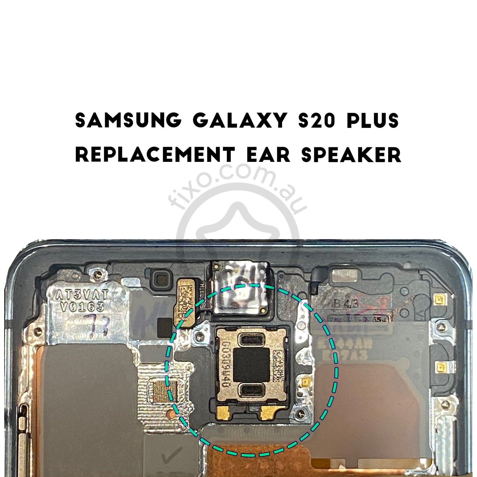
Step 39


– Take a pair of tweezers and gently insert one point into the notch at the bottom left corner of the earpiece speaker.
– Give it a little pry to break free the adhesive and pop out the earpiece speaker.
– Feel free to reuse the existing speaker adhesive when putting in a new speaker, but if it’s looking a bit worn out, you can easily swap it out with a pre-cut adhesive sheet.
Tools Used


